
Motherboard DIY Troubleshooting Guide
Page 1
® P4T-E Intel® 850 ATX Motherboard USER'S MANUAL
® P4T-E Intel® 850 ATX Motherboard USER'S MANUAL

Motherboard DIY Troubleshooting Guide
Page 4
...3.6 Central Processing Unit (CPU 25 3.7 Expansion Cards 29 3.8 External Connectors 32 3.9 Starting Up the First Time 43 4. FEATURES 10 2.2 P4T-E Motherboard Components 12 3. BIOS SETUP 45 4.1 Managing and Updating Your BIOS 45 4.1.1 Upon First Use of the Computer System 45 4.1.2 Updating BIOS ...PCI Configuration 65 4.4.4 Shadow Configuration 67 4.5 Power Menu 68 4.5.1 Power Up Control 70 4.5.2 Hardware Monitor 71 4.6 Boot Menu 72 4 ASUS P4T-E User's Manual FEATURES 8 2.1 The ASUS P4T-E 8 2. INTRODUCTION 7 1.1 How This Manual Is Organized 7 1.2 Item Checklist 7 2.
...3.6 Central Processing Unit (CPU 25 3.7 Expansion Cards 29 3.8 External Connectors 32 3.9 Starting Up the First Time 43 4. FEATURES 10 2.2 P4T-E Motherboard Components 12 3. BIOS SETUP 45 4.1 Managing and Updating Your BIOS 45 4.1.1 Upon First Use of the Computer System 45 4.1.2 Updating BIOS ...PCI Configuration 65 4.4.4 Shadow Configuration 67 4.5 Power Menu 68 4.5.1 Power Up Control 70 4.5.2 Hardware Monitor 71 4.6 Boot Menu 72 4 ASUS P4T-E User's Manual FEATURES 8 2.1 The ASUS P4T-E 8 2. INTRODUCTION 7 1.1 How This Manual Is Organized 7 1.2 Item Checklist 7 2.

Motherboard DIY Troubleshooting Guide
Page 5
SOFTWARE REFERENCE 79 6.1 ASUS PC Probe 79 6.2 ASUS Live Update 84 6.3 CyberLink PowerPlayer SE 85 6.4 CyberLink VideoLive Mail 86 7. CONTENTS 4.7 Exit Menu 74 5.1 Install Operating System 76 5.2 Start Windows 76 5. APPENDIX 89 7.1 Glossary 89 INDEX 93 ASUS P4T-E User's Manual 5 SOFTWARE SETUP 77 5.3 P4T-E Motherboard Support CD 77 6.
SOFTWARE REFERENCE 79 6.1 ASUS PC Probe 79 6.2 ASUS Live Update 84 6.3 CyberLink PowerPlayer SE 85 6.4 CyberLink VideoLive Mail 86 7. CONTENTS 4.7 Exit Menu 74 5.1 Install Operating System 76 5.2 Start Windows 76 5. APPENDIX 89 7.1 Glossary 89 INDEX 93 ASUS P4T-E User's Manual 5 SOFTWARE SETUP 77 5.3 P4T-E Motherboard Support CD 77 6.
Motherboard DIY Troubleshooting Guide
Page 7
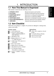
SOFTWARE SETUP 6. INTRODUCTION Manual / Checklist 1. INTRODUCTION 2. FEATURES 3. Intructions on setting up the BIOS Intructions on motherboard) (2) ASUS C-RIMM Continuity RIMM Optional Items ASUS IrDA-compliant infrared module Two Rambus Memory Modules LAN Card: PCI-L3C920 1394 Card: PCI-1394E ASUS P4T-E User's Manual 7 INTRODUCTION 1.1 How This Manual Is Organized This manual is complete. HARDWARE SETUP 4. BIOS...
SOFTWARE SETUP 6. INTRODUCTION Manual / Checklist 1. INTRODUCTION 2. FEATURES 3. Intructions on setting up the BIOS Intructions on motherboard) (2) ASUS C-RIMM Continuity RIMM Optional Items ASUS IrDA-compliant infrared module Two Rambus Memory Modules LAN Card: PCI-L3C920 1394 Card: PCI-1394E ASUS P4T-E User's Manual 7 INTRODUCTION 1.1 How This Manual Is Organized This manual is complete. HARDWARE SETUP 4. BIOS...

Motherboard DIY Troubleshooting Guide
Page 8
...-R/RW, LS-120, and Tape Backup drives. • JumperFree™ Mode: Now processor settings and easy overclocking of the processor's external frequency. 8 ASUS P4T-E User's Manual FEATURES 2.1 The ASUS P4T-E The ASUS P4T-E motherboard is carefully designed for the demanding PC user who wants advanced features processed by the fastest processors. 2.1.1 Core Specifications • Intel Processor Support...
...-R/RW, LS-120, and Tape Backup drives. • JumperFree™ Mode: Now processor settings and easy overclocking of the processor's external frequency. 8 ASUS P4T-E User's Manual FEATURES 2.1 The ASUS P4T-E The ASUS P4T-E motherboard is carefully designed for the demanding PC user who wants advanced features processed by the fastest processors. 2.1.1 Core Specifications • Intel Processor Support...

Motherboard DIY Troubleshooting Guide
Page 10
... ASUS P4T-E User's Manual With these features implemented in two channels. While PC100 SDRAM modules operate at up to communicate within a standard protocol creating a higher level of 0.8GB/s, MCH dual channel Rambus DRAMs can be enabled.) • RDRAM Optimized Performance: This motherboard ...and supports Enhanced IDE devices, such as CPU and systerm voltages, temperatures, and fan status through the onboard hardware and the bundled ASUS PC Probe or Intel LDCM software. • Desktop Management Interface (DMI): Supports DMI through BIOS, which allows hardware to four analog...
... ASUS P4T-E User's Manual With these features implemented in two channels. While PC100 SDRAM modules operate at up to communicate within a standard protocol creating a higher level of 0.8GB/s, MCH dual channel Rambus DRAMs can be enabled.) • RDRAM Optimized Performance: This motherboard ...and supports Enhanced IDE devices, such as CPU and systerm voltages, temperatures, and fan status through the onboard hardware and the bundled ASUS PC Probe or Intel LDCM software. • Desktop Management Interface (DMI): Supports DMI through BIOS, which allows hardware to four analog...

Motherboard DIY Troubleshooting Guide
Page 11
... system overheat and system damage, this motherboard is enabled, the CPU with either the bundled ASUS PC Probe or Intel LDCM will enter the Soft-Off mode. • Peripheral Power Up: Keyboard or Mouse power up to critical motherboard components. ASUS P4T-E User's Manual 11 When auto throttling... is a new technology to normal level. The onboard hardware ASUS ASIC in 3.8 Connectors for speed and failure. All the fans are set for ...
... system overheat and system damage, this motherboard is enabled, the CPU with either the bundled ASUS PC Probe or Intel LDCM will enter the Soft-Off mode. • Peripheral Power Up: Keyboard or Mouse power up to critical motherboard components. ASUS P4T-E User's Manual 11 When auto throttling... is a new technology to normal level. The onboard hardware ASUS ASIC in 3.8 Connectors for speed and failure. All the fans are set for ...
Motherboard DIY Troubleshooting Guide
Page 12
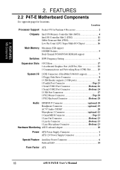
2. FEATURES 2.2 P4T-E Motherboard Components See opposite page for Pentium 4 Processors 2 Chipsets Intel 850 Memory Controller Hub (MCH 4 Intel I/O Controller Hub 2 (ICH2 11 2Mbit Firmware Hub (FWH 13 ... 23 1 Line In Connector Bottom) 23 1 Line Microphone Connector Bottom) 23 Hardware Monitoring ASUS onboard chipset 10 Power ATX Power Supply Connector 1 ATX 12V Power Supply Connector 3 Special Feature Auxillary Power Connector 6 Onboard LED 14 Form Factor ATX 12 ASUS P4T-E User's Manual FEATURES MB Components 2. Location Processor Support Socket 478 for locations.
2. FEATURES 2.2 P4T-E Motherboard Components See opposite page for Pentium 4 Processors 2 Chipsets Intel 850 Memory Controller Hub (MCH 4 Intel I/O Controller Hub 2 (ICH2 11 2Mbit Firmware Hub (FWH 13 ... 23 1 Line In Connector Bottom) 23 1 Line Microphone Connector Bottom) 23 Hardware Monitoring ASUS onboard chipset 10 Power ATX Power Supply Connector 1 ATX 12V Power Supply Connector 3 Special Feature Auxillary Power Connector 6 Onboard LED 14 Form Factor ATX 12 ASUS P4T-E User's Manual FEATURES MB Components 2. Location Processor Support Socket 478 for locations.

Motherboard DIY Troubleshooting Guide
Page 14
... 30.5cm (12.0in) 3. HARDWARE SETUP 3.1 P4T-E Motherboard Layout PS/2KBMS T: Mouse B: Keyboard USB T: Port1 B: Port2 COM1 ...CPU_FAN MIC2 FLOPPY Accelerated Graphics Port (AGP Pro) Audio Codec HEADPHONE JR1 PCI1 PCI2 SPDIFOUT Super I/O PCI3 P4T-E PCI4 PCI5 SMB IR CNR_SLOT ADN CR2032 3V Lithium Cell CMOS Power Intel I/O Controller Hub (ICH2) ...HDDLED LED 2Mbit Firmware Hub J3J3+ USB2 ASUS ASIC with Hardware Monitor PCI_FAN JEN DIP Switches OC3 CHASSIS PANEL Grayed components are available only on certain models at the time of purchase. 14 ASUS P4T-E User's Manual 3.
... 30.5cm (12.0in) 3. HARDWARE SETUP 3.1 P4T-E Motherboard Layout PS/2KBMS T: Mouse B: Keyboard USB T: Port1 B: Port2 COM1 ...CPU_FAN MIC2 FLOPPY Accelerated Graphics Port (AGP Pro) Audio Codec HEADPHONE JR1 PCI1 PCI2 SPDIFOUT Super I/O PCI3 P4T-E PCI4 PCI5 SMB IR CNR_SLOT ADN CR2032 3V Lithium Cell CMOS Power Intel I/O Controller Hub (ICH2) ...HDDLED LED 2Mbit Firmware Hub J3J3+ USB2 ASUS ASIC with Hardware Monitor PCI_FAN JEN DIP Switches OC3 CHASSIS PANEL Grayed components are available only on certain models at the time of purchase. 14 ASUS P4T-E User's Manual 3.
Motherboard DIY Troubleshooting Guide
Page 15
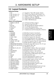
Freq. HARDWARE SETUP 3.2 Layout Contents Motherboard Settings 1) JEN p. 18 JumperFree™ Mode (JEN) (Disable / Enable) 2) SW1 (Switches 6-10) p. 19 CPU Ext. Selection (SW1 Switches 6-10) 3) SW1 (Switches 1-4) p. 20 Manual CPU Ratio ... System Management Interrupt Switch Lead (2 pin) 26) PWRSW (PANEL) p.47 ATX Power / Soft-Off Switch Lead (2 pin) 27) RESET (PANEL) p.48 Reset Switch Lead (2 pin) ASUS P4T-E User's Manual 15 H/W SETUP Layout Contents 3. 3.
Freq. HARDWARE SETUP 3.2 Layout Contents Motherboard Settings 1) JEN p. 18 JumperFree™ Mode (JEN) (Disable / Enable) 2) SW1 (Switches 6-10) p. 19 CPU Ext. Selection (SW1 Switches 6-10) 3) SW1 (Switches 1-4) p. 20 Manual CPU Ratio ... System Management Interrupt Switch Lead (2 pin) 26) PWRSW (PANEL) p.47 ATX Power / Soft-Off Switch Lead (2 pin) 27) RESET (PANEL) p.48 Reset Switch Lead (2 pin) ASUS P4T-E User's Manual 15 H/W SETUP Layout Contents 3. 3.
Motherboard DIY Troubleshooting Guide
Page 16
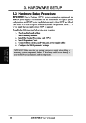
3. HARDWARE SETUP 3.3 Hardware Setup Procedure IMPORTANT: Due to your computer: 1. Check motherboard settings 2. Install the Central Processing Unit (CPU) 4. Configure the BIOS parameter settings WARNING! Install memory modules 3. H/W SETUP Getting Started 16 ASUS P4T-E User's Manual Make sure that can supply at least 230W and at least 300W is required. Failure to... Cards 5. For typical system configurations, an ATX12V power supply that can supply at least 8.5A on the +12V lead is recommended for this motherboard. Complete the following steps before using your...
3. HARDWARE SETUP 3.3 Hardware Setup Procedure IMPORTANT: Due to your computer: 1. Check motherboard settings 2. Install the Central Processing Unit (CPU) 4. Configure the BIOS parameter settings WARNING! Install memory modules 3. H/W SETUP Getting Started 16 ASUS P4T-E User's Manual Make sure that can supply at least 230W and at least 300W is required. Failure to... Cards 5. For typical system configurations, an ATX12V power supply that can supply at least 8.5A on the +12V lead is recommended for this motherboard. Complete the following steps before using your...

Motherboard DIY Troubleshooting Guide
Page 17
... work on the inside. 2. Hold components by the edges and try not to touch the IC chips, leads or connectors, or other components. 4. H/W SETUP Motherboard Settings ASUS P4T-E User's Manual 17 WARNING! Ensure that came with the component whenever the components are separated from static electricity, you should follow some precautions whenever you...
... work on the inside. 2. Hold components by the edges and try not to touch the IC chips, leads or connectors, or other components. 4. H/W SETUP Motherboard Settings ASUS P4T-E User's Manual 17 WARNING! Ensure that came with the component whenever the components are separated from static electricity, you should follow some precautions whenever you...

Motherboard DIY Troubleshooting Guide
Page 18
... Mode) [1-2] JEN SW1 ON OFF 1 2 3 4 5 6 7 8 9 10 P4T-E 12 Jumper Mode P4T-E JumperFree™ Mode Setting 23 Jumper Free (Default) 18 ASUS P4T-E User's Manual The illustration below shows all the switches in the OFF position. Frequency Selection 8. 3. Frequency Multiple 2. Reserved 6. HARDWARE SETUP Motherboard Frequency Settings (SW1 Switches) The motherboard frequency is adjusted through the BIOS setup...
... Mode) [1-2] JEN SW1 ON OFF 1 2 3 4 5 6 7 8 9 10 P4T-E 12 Jumper Mode P4T-E JumperFree™ Mode Setting 23 Jumper Free (Default) 18 ASUS P4T-E User's Manual The illustration below shows all the switches in the OFF position. Frequency Selection 8. 3. Frequency Multiple 2. Reserved 6. HARDWARE SETUP Motherboard Frequency Settings (SW1 Switches) The motherboard frequency is adjusted through the BIOS setup...

Motherboard DIY Troubleshooting Guide
Page 19
... 68.0MHz 34.0MHz ON 1 2 3 4 5 6 7 8 9 10 105.0MHz 70.0MHz 35.0MHz ON 1 2 3 4 5 6 7 8 9 10 110.0MHz 73.0MHz 36.0MHz ON 1 2 3 4 5 6 7 8 9 10 WARNING! H/W SETUP Motherboard Settings ASUS P4T-E User's Manual 19 HARDWARE SETUP 2) CPU External Frequency Selection (SW1 Switches 6-10) This option tells the clock generator what frequency to send to the CPU...
... 68.0MHz 34.0MHz ON 1 2 3 4 5 6 7 8 9 10 105.0MHz 70.0MHz 35.0MHz ON 1 2 3 4 5 6 7 8 9 10 110.0MHz 73.0MHz 36.0MHz ON 1 2 3 4 5 6 7 8 9 10 WARNING! H/W SETUP Motherboard Settings ASUS P4T-E User's Manual 19 HARDWARE SETUP 2) CPU External Frequency Selection (SW1 Switches 6-10) This option tells the clock generator what frequency to send to the CPU...

Motherboard DIY Troubleshooting Guide
Page 20
Set the DSW switches according to User Define under 4.4 Advanced Menu in 3, HARDWARE SETUP.) 2. H/W SETUP Motherboard Settings P4T-E P4T-E CPU Frequency Multiple Selection SW1 ON ON ON ON 1 2 3 4 5 6 7 8 9 10 8.0x ON 1 2 3 4 5 6 7 8 9 10 10.0x ON 1 2 3 4 5 6 7 8 9 10 11.0x ON 1 2 3 4 5 6 7 8 9 10 12.0x ON 1 ...[ON] [ON] [ON] [ON] 4 [OFF] [OFF] [OFF] [OFF] [OFF] [OFF] [OFF] [OFF] [ON] [ON] [ON] [ON] [ON] [ON] [ON] [ON] 20 ASUS P4T-E User's Manual To use BIOS setup in place of these switches. (Set Operating Frequency Setting to the internal speed of bus speeds with CPU settings...
Set the DSW switches according to User Define under 4.4 Advanced Menu in 3, HARDWARE SETUP.) 2. H/W SETUP Motherboard Settings P4T-E P4T-E CPU Frequency Multiple Selection SW1 ON ON ON ON 1 2 3 4 5 6 7 8 9 10 8.0x ON 1 2 3 4 5 6 7 8 9 10 10.0x ON 1 2 3 4 5 6 7 8 9 10 11.0x ON 1 2 3 4 5 6 7 8 9 10 12.0x ON 1 ...[ON] [ON] [ON] [ON] 4 [OFF] [OFF] [OFF] [OFF] [OFF] [OFF] [OFF] [OFF] [ON] [ON] [ON] [ON] [ON] [ON] [ON] [ON] 20 ASUS P4T-E User's Manual To use BIOS setup in place of these switches. (Set Operating Frequency Setting to the internal speed of bus speeds with CPU settings...
Motherboard DIY Troubleshooting Guide
Page 21
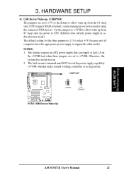
...requires an ATX power supply that can supply at least 2A on the +5VSB lead when these jumpers are set to CPU; H/W SETUP Motherboard Settings ASUS P4T-E User's Manual 21 RAM refreshed; RAM in low power mode) using the connected USB devices. system running in slow refresh; The total... to allow wake up from the S1 sleep state (CPU stopped; power supply in sleep mode. NOTES: 1. USBPWR 2 1 +5VSB 3 2 +5V (Default) P4T-E P4T-E USB Device Wake Up 3. HARDWARE SETUP 4) USB Device Wake-up . 2. Otherwise, the system does not power up (USBPWR) The jumpers are set to +5V...
...requires an ATX power supply that can supply at least 2A on the +5VSB lead when these jumpers are set to CPU; H/W SETUP Motherboard Settings ASUS P4T-E User's Manual 21 RAM refreshed; RAM in low power mode) using the connected USB devices. system running in slow refresh; The total... to allow wake up from the S1 sleep state (CPU stopped; power supply in sleep mode. NOTES: 1. USBPWR 2 1 +5VSB 3 2 +5V (Default) P4T-E P4T-E USB Device Wake Up 3. HARDWARE SETUP 4) USB Device Wake-up . 2. Otherwise, the system does not power up (USBPWR) The jumpers are set to +5V...
Motherboard DIY Troubleshooting Guide
Page 22
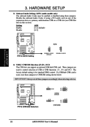
Setting Enable Disable ADN [1-2] (default) [2-3] P4T-E P4T-E AUDIO Setting ADN 2 1 ENABLE AUDIO (Default) 3 2 DISABLE AUDIO 6) USB2 / CNRUSB Selection (J3-J3+, OC3) The CNR slot can support an optional USB hub CNR card.... card is for standard USB2 control. 3. IMPORTANT! H/W SETUP Motherboard Settings 3. Three jumpers are used , reset these jumpers. The factory default setting is used to CNRUSB setting shown below. P4T-E P4T-E CNR/USB Selection 12 OC3 12 J3J3+ USB2 (Default) 23 OC3 23 J3J3+ CNRUSB 22 ASUS P4T-E User's Manual Disable the onboard Audio Codec if...
Setting Enable Disable ADN [1-2] (default) [2-3] P4T-E P4T-E AUDIO Setting ADN 2 1 ENABLE AUDIO (Default) 3 2 DISABLE AUDIO 6) USB2 / CNRUSB Selection (J3-J3+, OC3) The CNR slot can support an optional USB hub CNR card.... card is for standard USB2 control. 3. IMPORTANT! H/W SETUP Motherboard Settings 3. Three jumpers are used , reset these jumpers. The factory default setting is used to CNRUSB setting shown below. P4T-E P4T-E CNR/USB Selection 12 OC3 12 J3J3+ USB2 (Default) 23 OC3 23 J3J3+ CNRUSB 22 ASUS P4T-E User's Manual Disable the onboard Audio Codec if...

Motherboard DIY Troubleshooting Guide
Page 23
When C-RIMMs are a serial connection in a Rambus interface, such as used in this motherboard. HARDWARE SETUP 3.5 System Memory NOTE: No hardware or BIOS setup is recommended that you use when socket will not be identical (see ...or removing memory. This motherboard has four 184-pin Rambus Inline Memory Modules (RIMM) sockets. The memory configuration of a Rambus interface. 3. a. b. 128MB RDRAM RIMMB2 C-RIMM RIMMB1 128MB RDRAM C-RIMM RIMMA2 RIMMA1 c. 128MB RDRAM RIMMB2 128MB RDRAM RIMMB1 128MB RDRAM 128MB RDRAM RIMMA2 RIMMA1 ASUS P4T-E User's Manual 23 ...
When C-RIMMs are a serial connection in a Rambus interface, such as used in this motherboard. HARDWARE SETUP 3.5 System Memory NOTE: No hardware or BIOS setup is recommended that you use when socket will not be identical (see ...or removing memory. This motherboard has four 184-pin Rambus Inline Memory Modules (RIMM) sockets. The memory configuration of a Rambus interface. 3. a. b. 128MB RDRAM RIMMB2 C-RIMM RIMMB1 128MB RDRAM C-RIMM RIMMA2 RIMMA1 c. 128MB RDRAM RIMMB2 128MB RDRAM RIMMB1 128MB RDRAM 128MB RDRAM RIMMA2 RIMMA1 ASUS P4T-E User's Manual 23 ...

Motherboard DIY Troubleshooting Guide
Page 25
... forget to scrape the motherboard surface when mounting a clamp-style processor fan, or else damage may occur! Gold Arrow 90 - 100 CAUTION! Take care not to set the correct Bus Frequency and Multiple (frequency multiple setting is not needed. ASUS P4T-E User's Manual 25 ... overheating. Then lift the lever upwards. CAUTION! Do not force the CPU into place. H/W SETUP CPU P4T-E P4T-E Socket 478 1. HARDWARE SETUP 3.6 Central Processing Unit (CPU) The motherboard provides a ZIF Socket 478, for bent pins. 3. Gold Arrow 3. Purchase and install a fan and heatsink...
... forget to scrape the motherboard surface when mounting a clamp-style processor fan, or else damage may occur! Gold Arrow 90 - 100 CAUTION! Take care not to set the correct Bus Frequency and Multiple (frequency multiple setting is not needed. ASUS P4T-E User's Manual 25 ... overheating. Then lift the lever upwards. CAUTION! Do not force the CPU into place. H/W SETUP CPU P4T-E P4T-E Socket 478 1. HARDWARE SETUP 3.6 Central Processing Unit (CPU) The motherboard provides a ZIF Socket 478, for bent pins. 3. Gold Arrow 3. Purchase and install a fan and heatsink...

Motherboard DIY Troubleshooting Guide
Page 26
... on the motherboard. Note that the retention module base is purchased separately, only use a model with fin-ends that your CPU fan is working. H/W SETUP CPU Heatsink WARNING! 3. NOTE: If using a rectangular heatsink, use an Intel certified heatsink and fan. If a CPU is already installed on the shorter side. 26 ASUS P4T-E User...
... on the motherboard. Note that the retention module base is purchased separately, only use a model with fin-ends that your CPU fan is working. H/W SETUP CPU Heatsink WARNING! 3. NOTE: If using a rectangular heatsink, use an Intel certified heatsink and fan. If a CPU is already installed on the shorter side. 26 ASUS P4T-E User...


