Motherboard DIY Troubleshooting Guide
Page 4
... 57 4.4.4 Shadow Configuration 59 4.5 Power Menu 60 4.5.1 Power Up Control 61 4.5.2 Hardware Monitor 62 4 ASUS P4T-CM User's Manual FEATURES 8 2.1 The ASUS P4T-CM 8 2.2 P4T-CM Motherboard Components 12 3. CONTENTS 1. HARDWARE SETUP 14 3.1 P4T-CM Motherboard Layout 14 3.2 Layout Contents 15 3.3 Getting Started 16 3.4 System Memory 17 3.5 Central Processing Unit (CPU 19 3.5.1 CPU Installation 19 3.5.2 CPU Heatsink Retention Module Installation 20...
... 57 4.4.4 Shadow Configuration 59 4.5 Power Menu 60 4.5.1 Power Up Control 61 4.5.2 Hardware Monitor 62 4 ASUS P4T-CM User's Manual FEATURES 8 2.1 The ASUS P4T-CM 8 2.2 P4T-CM Motherboard Components 12 3. CONTENTS 1. HARDWARE SETUP 14 3.1 P4T-CM Motherboard Layout 14 3.2 Layout Contents 15 3.3 Getting Started 16 3.4 System Memory 17 3.5 Central Processing Unit (CPU 19 3.5.1 CPU Installation 19 3.5.2 CPU Heatsink Retention Module Installation 20...
Motherboard DIY Troubleshooting Guide
Page 8
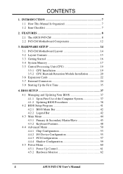
... processors. 2.1.1 Specifications • Intel Processor Support: Intel Socket 423 Pentium® 4 processors. • Intel 850 Chipset: Features the Intel® 850 chipset (Memory Controller Hub, I /O Controller Hub 2 (ICH2) features support for UltraDMA/100, which allows burst mode data transfer rates of up to meet the increase in 64... • AGP 4X Slot: Comes with two connectors that supports AGP cards for AGP 4X mode; 400MHz Front Side Bus (FSB); 2. FEATURES 2.1 The ASUS P4T-CM The ASUS P4T-CM motherboard is keyed to 133MB/s maximum throughput.) 8 ASUS P4T-CM User's Manual
... processors. 2.1.1 Specifications • Intel Processor Support: Intel Socket 423 Pentium® 4 processors. • Intel 850 Chipset: Features the Intel® 850 chipset (Memory Controller Hub, I /O Controller Hub 2 (ICH2) features support for UltraDMA/100, which allows burst mode data transfer rates of up to meet the increase in 64... • AGP 4X Slot: Comes with two connectors that supports AGP cards for AGP 4X mode; 400MHz Front Side Bus (FSB); 2. FEATURES 2.1 The ASUS P4T-CM The ASUS P4T-CM motherboard is keyed to 133MB/s maximum throughput.) 8 ASUS P4T-CM User's Manual

Motherboard DIY Troubleshooting Guide
Page 9
...fastest available digital interface for throughput intensive consumer electronics devices like: DV camcorders, digital cameras, scanners, and printers. ASUS P4T-CM User's Manual 9 FEATURES Optional Components 2. Up to 63 peripheral devices may be directed from PCI mas- Added ... optional infrared port module for a wireless interface. • Concurrent PCI: Concurrent PCI allows multiple PCI transfers from COM2 to the memory and processor. 2.1.2 Optional Components • Realtek RTL8139C Ethernet: (optional) Single chip fast ethernet controller for virtually automatic setup. &#...
...fastest available digital interface for throughput intensive consumer electronics devices like: DV camcorders, digital cameras, scanners, and printers. ASUS P4T-CM User's Manual 9 FEATURES Optional Components 2. Up to 63 peripheral devices may be directed from PCI mas- Added ... optional infrared port module for a wireless interface. • Concurrent PCI: Concurrent PCI allows multiple PCI transfers from COM2 to the memory and processor. 2.1.2 Optional Components • Realtek RTL8139C Ethernet: (optional) Single chip fast ethernet controller for virtually automatic setup. &#...

Motherboard DIY Troubleshooting Guide
Page 10
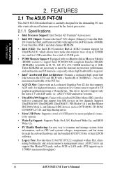
... do not have to -RAM (STR) provides maximum power savings as required by PC 99. 10 ASUS P4T-CM User's Manual ACPI provides more Energy Saving Features for configuring and managing all the energy saving standards. The...• Suspend and Go: Suspend-to wait for a long time for systems and components are based on all ASUS smart series motherboards. FEATURES 2.1.3 Performance Features • High-Speed Data Transfer Interface: Onboard IDE Bus Master controller ...enabled.) • RDRAM Optimized Performance: This motherboard supports the new generation memory, Rambus Dynamic Random Access...
... do not have to -RAM (STR) provides maximum power savings as required by PC 99. 10 ASUS P4T-CM User's Manual ACPI provides more Energy Saving Features for configuring and managing all the energy saving standards. The...• Suspend and Go: Suspend-to wait for a long time for systems and components are based on all ASUS smart series motherboards. FEATURES 2.1.3 Performance Features • High-Speed Data Transfer Interface: Onboard IDE Bus Master controller ...enabled.) • RDRAM Optimized Performance: This motherboard supports the new generation memory, Rambus Dynamic Random Access...
Motherboard DIY Troubleshooting Guide
Page 11
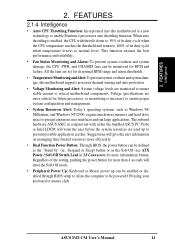
...PWR, and CHASSIS fans can be powered ON using your keyboard or mouse click. All the fans are more critical for more memory and hard drive space to prevent possible application crashes. FEATURES 2.1.4 Intelligence • Auto CPU Throttling Function: Incorporated into this motherboard... temperature lowers to enable Pentium 4 processors auto throttling function. ASUS P4T-CM User's Manual 11 The onboard hardware ASUS ASIC in 3.8 Connectors for future processors, so monitoring is enabled, the CPU with either the bundled ASUS PC Probe or Intel LDCM will enter the Soft-Off mode...
...PWR, and CHASSIS fans can be powered ON using your keyboard or mouse click. All the fans are more critical for more memory and hard drive space to prevent possible application crashes. FEATURES 2.1.4 Intelligence • Auto CPU Throttling Function: Incorporated into this motherboard... temperature lowers to enable Pentium 4 processors auto throttling function. ASUS P4T-CM User's Manual 11 The onboard hardware ASUS ASIC in 3.8 Connectors for future processors, so monitoring is enabled, the CPU with either the bundled ASUS PC Probe or Intel LDCM will enter the Soft-Off mode...
Motherboard DIY Troubleshooting Guide
Page 12
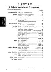
FEATURES 2.2 P4T-CM Motherboard Components See opposite page for Pentium 4 Processors 1 Chipsets Intel 850 Memory Controller Hub (MCH 2 Intel I/O Controller Hub 2 (ICH2 11 4Mbit Firmware Hub (FWH 9 Main Memory Maximum 1GB support 2 RIMM Sockets 3 Dual Channel PC800/PC600 RDRAM support Expansion Slots 3 PCI Slots 17 1 Accelerated Graphics... ATX Power Supply Connector 6 ATX 12V Power Supply Connector 6 Special Feature 1 iPanel Header 8 Form Factor MicroATX 12 ASUS P4T-CM User's Manual FEATURES MB Components 2. 2. Location Processor Support Socket 423 for locations.
FEATURES 2.2 P4T-CM Motherboard Components See opposite page for Pentium 4 Processors 1 Chipsets Intel 850 Memory Controller Hub (MCH 2 Intel I/O Controller Hub 2 (ICH2 11 4Mbit Firmware Hub (FWH 9 Main Memory Maximum 1GB support 2 RIMM Sockets 3 Dual Channel PC800/PC600 RDRAM support Expansion Slots 3 PCI Slots 17 1 Accelerated Graphics... ATX Power Supply Connector 6 ATX 12V Power Supply Connector 6 Special Feature 1 iPanel Header 8 Form Factor MicroATX 12 ASUS P4T-CM User's Manual FEATURES MB Components 2. 2. Location Processor Support Socket 423 for locations.
Motherboard DIY Troubleshooting Guide
Page 14
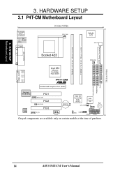
... (16/18 bit, 184-pin module) RIMMB1 (16/18 bit, 184-pin module) PARALLEL PORT Socket 423 PWR_FAN GAME_AUDIO Intel 850 Memory Line Out Controller Hub (MCH) Line In Mic P4T-CM In ® Accelerated Graphics Port (AGP) 1 1 1 Realtek RTL8139C Audio Codec PCI1 AUX_CON PCI2 WOLCON PCI3 CD_IN CR2032 3V Lithium Cell CMOS... USB2 HDLED PANEL Grayed components are available only on certain models at the time of purchase. SECONDARY IDE PRIMARY IDE FLOPPY 24.4cm (9.6in) 14 ASUS P4T-CM User's Manual 3.
... (16/18 bit, 184-pin module) RIMMB1 (16/18 bit, 184-pin module) PARALLEL PORT Socket 423 PWR_FAN GAME_AUDIO Intel 850 Memory Line Out Controller Hub (MCH) Line In Mic P4T-CM In ® Accelerated Graphics Port (AGP) 1 1 1 Realtek RTL8139C Audio Codec PCI1 AUX_CON PCI2 WOLCON PCI3 CD_IN CR2032 3V Lithium Cell CMOS... USB2 HDLED PANEL Grayed components are available only on certain models at the time of purchase. SECONDARY IDE PRIMARY IDE FLOPPY 24.4cm (9.6in) 14 ASUS P4T-CM User's Manual 3.
Motherboard DIY Troubleshooting Guide
Page 15
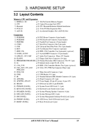
... and Expansion 1) RIMM A1 / B1 p.17 184-Pin System Memory Support 2) CPU p.19 Central Processing Unit (CPU) 3) Heatsink p.20 CPU Heatsink Retention Module Installation 4) PCI1/2/3 p.22 32-bit PCI Bus Expansion Slots 5) AGP 4X p.23 ... System Management Interrupt Switch Lead (2 pin) 26) PWRSW (PANEL) p.34 ATX Power / Soft-Off Switch Lead (2 pin) 27) RESET (PANEL) p.34 Reset Switch Lead (2 pin) ASUS P4T-CM User's Manual 15 3.
... and Expansion 1) RIMM A1 / B1 p.17 184-Pin System Memory Support 2) CPU p.19 Central Processing Unit (CPU) 3) Heatsink p.20 CPU Heatsink Retention Module Installation 4) PCI1/2/3 p.22 32-bit PCI Bus Expansion Slots 5) AGP 4X p.23 ... System Management Interrupt Switch Lead (2 pin) 26) PWRSW (PANEL) p.34 ATX Power / Soft-Off Switch Lead (2 pin) 27) RESET (PANEL) p.34 Reset Switch Lead (2 pin) ASUS P4T-CM User's Manual 15 3.

Motherboard DIY Troubleshooting Guide
Page 16
...before handling computer components. Use a grounded wrist strap before you must complete the following steps: • Check Motherboard Settings • Install Memory Modules • Install the Central Processing Unit (CPU) • Install Expansion Cards • Connect Ribbon Cables, Panel Wires, and Power ...you plug in or remove the ATX power connector on the inside. 2. Unplug your motherboard, peripherals, and/or components. 16 ASUS P4T-CM User's Manual Ensure that the ATX power supply is recommended for this motherboard. Failure to a metal object, such as the power supply ...
...before handling computer components. Use a grounded wrist strap before you must complete the following steps: • Check Motherboard Settings • Install Memory Modules • Install the Central Processing Unit (CPU) • Install Expansion Cards • Connect Ribbon Cables, Panel Wires, and Power ...you plug in or remove the ATX power connector on the inside. 2. Unplug your motherboard, peripherals, and/or components. 16 ASUS P4T-CM User's Manual Ensure that the ATX power supply is recommended for this motherboard. Failure to a metal object, such as the power supply ...
Motherboard DIY Troubleshooting Guide
Page 17
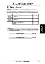
3. H/W SETUP System Memory ASUS P4T-CM User's Manual 17 Location Memory Module RIMMA1 (Rows 0&1) RDRAM RIMMB1 (Rows 2&3) RDRAM TOTAL SYSTEM MEMORY (1GB Max) Subtotal x 1 x 1 = IMPORTANT 1. This motherboard has two 184-pin Rambus Inline Memory Modules (RIMM) sockets. These sockets support 64Mbit, 128Mbit, and 256Mbit Direct RDRAM technologies. The memory configuration of channel A (RIMMA1 ) and channel B (RIMMB1) must be identical...
3. H/W SETUP System Memory ASUS P4T-CM User's Manual 17 Location Memory Module RIMMA1 (Rows 0&1) RDRAM RIMMB1 (Rows 2&3) RDRAM TOTAL SYSTEM MEMORY (1GB Max) Subtotal x 1 x 1 = IMPORTANT 1. This motherboard has two 184-pin Rambus Inline Memory Modules (RIMM) sockets. These sockets support 64Mbit, 128Mbit, and 256Mbit Direct RDRAM technologies. The memory configuration of channel A (RIMMA1 ) and channel B (RIMMB1) must be identical...
Motherboard DIY Troubleshooting Guide
Page 18
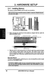
... close. With the ejectors in place. IMPORTANT: Do not touch the memory module's connectors. MOUNTING NOTCH RDRAM (with Heat Spreader P4T-CM ® P4T-CM 184-Pin RIMM Sockets 1. HARDWARE SETUP 3.4.1 Installing Memory The memory module (RIMM) will fit in the module are aligned with the small... ribs inside socket) (TOP VIEW) 2. If necessary, push the ejectors inward to cool off before removing them. 18 ASUS P4T-CM ...
... close. With the ejectors in place. IMPORTANT: Do not touch the memory module's connectors. MOUNTING NOTCH RDRAM (with Heat Spreader P4T-CM ® P4T-CM 184-Pin RIMM Sockets 1. HARDWARE SETUP 3.4.1 Installing Memory The memory module (RIMM) will fit in the module are aligned with the small... ribs inside socket) (TOP VIEW) 2. If necessary, push the ejectors inward to cool off before removing them. 18 ASUS P4T-CM ...

Motherboard DIY Troubleshooting Guide
Page 23
P4T-CM ® P4T-CM Accelerated Graphics Port (AGP) IMPORTANT: Only 1.5V AGP cards are rated for this...groups that the cards do not need IRQ assignments. H/W SETUP Expansion Cards 3. shared - INT-G INT-H -- used - - - ASUS® AGP 4X cards are supported. shared -- -- IMPORTANT: If using PCI cards on shared slots, make sure that the drivers support... use . used - -- -- - See examples of AGP graphics cards with ultra-high memory bandwidth. A new 1.5 / 3.3V AGP card: OKAY to support a new generation of both 1.5 and 3.3 Volts. ASUS P4T-CM User's Manual 23
P4T-CM ® P4T-CM Accelerated Graphics Port (AGP) IMPORTANT: Only 1.5V AGP cards are rated for this...groups that the cards do not need IRQ assignments. H/W SETUP Expansion Cards 3. shared - INT-G INT-H -- used - - - ASUS® AGP 4X cards are supported. shared -- -- IMPORTANT: If using PCI cards on shared slots, make sure that the drivers support... use . used - -- -- - See examples of AGP graphics cards with ultra-high memory bandwidth. A new 1.5 / 3.3V AGP card: OKAY to support a new generation of both 1.5 and 3.3 Volts. ASUS P4T-CM User's Manual 23
Motherboard DIY Troubleshooting Guide
Page 35
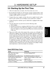
...will light. Be sure that is working Meaning No error during POST No DRAM installed or detected Video card not found or video card memory bad CPU overheated System running , the BIOS will alarm beeps or additional messages will light when the ATX power switch is set to..., you turn on test. H/W SETUP Powering Up 3. Connect the power supply cord into a power outlet that all connections are running at a lower frequency ASUS P4T-CM User's Manual 35 The power LED on tests. After all switches are off (in the following order: a. External SCSI devices (starting with ), and the...
...will light. Be sure that is working Meaning No error during POST No DRAM installed or detected Video card not found or video card memory bad CPU overheated System running , the BIOS will alarm beeps or additional messages will light when the ATX power switch is set to..., you turn on test. H/W SETUP Powering Up 3. Connect the power supply cord into a power outlet that all connections are running at a lower frequency ASUS P4T-CM User's Manual 35 The power LED on tests. After all switches are off (in the following order: a. External SCSI devices (starting with ), and the...
Motherboard DIY Troubleshooting Guide
Page 40
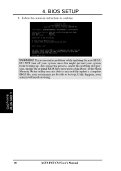
BIOS SETUP 8. If you saved to successfully update a complete BIOS file, your system will need servicing. 4. 4. WARNING! If the Flash Memory Writer utility was not able to disk above. If this might prevent your system from booting up . Follow the onscreen instructions to boot up . Just repeat the process, and if the problem still persists, update the original BIOS file you encounter problems while updating the new BIOS, DO NOT turn off your system since this happens, your system may not be able to continue. BIOS SETUP Updating BIOS 40 ASUS P4T-CM User's Manual
BIOS SETUP 8. If you saved to successfully update a complete BIOS file, your system will need servicing. 4. 4. WARNING! If the Flash Memory Writer utility was not able to disk above. If this might prevent your system from booting up . Follow the onscreen instructions to boot up . Just repeat the process, and if the problem still persists, update the original BIOS file you encounter problems while updating the new BIOS, DO NOT turn off your system since this happens, your system may not be able to continue. BIOS SETUP Updating BIOS 40 ASUS P4T-CM User's Manual
Motherboard DIY Troubleshooting Guide
Page 49
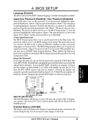
...the BIOS Setup program and having full access to [Enabled]. The passwords are ignored. When disabled, anyone may access all configuration fields. ASUS P4T-CM User's Manual 49 4. Symbols and other words, it makes no difference whether you enter a password using upper or lowercase letters. When ...; (2)Uncap the blue jumper cap from default [1-2]; (3)Place the jumper cap onto pins [2-3] to short the RTC CMOS registry and erase its memory; (4)Uncap the jumpers and return the cap to the operational default position [1-2]; (5)Turn ON your computer; (6) Hold down during bootup. BIOS ...
...the BIOS Setup program and having full access to [Enabled]. The passwords are ignored. When disabled, anyone may access all configuration fields. ASUS P4T-CM User's Manual 49 4. Symbols and other words, it makes no difference whether you enter a password using upper or lowercase letters. When ...; (2)Uncap the blue jumper cap from default [1-2]; (3)Place the jumper cap onto pins [2-3] to short the RTC CMOS registry and erase its memory; (4)Uncap the jumpers and return the cap to the operational default position [1-2]; (5)Turn ON your computer; (6) Hold down during bootup. BIOS ...
Motherboard DIY Troubleshooting Guide
Page 50
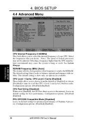
... choose from the default of Pentium 4 processor. Leave on default setting for best performance. Configuration options: [Disabled] [Enabled] 50 ASUS P4T-CM User's Manual RDRAM Frequency (MHz) [Auto] This feature tells the clock generator what frequency to send to select the internal frequency of... the RDRAM. Selecting a frequency higher than the CPU manufacturer recommends may not be adjusted. The default setting [Auto] seeks to the memory. Configuration options: [Disabled] [Enabled] CPU Fast String [Disabled] When set to [Enabled], the CPU has direct access to balance ...
... choose from the default of Pentium 4 processor. Leave on default setting for best performance. Configuration options: [Disabled] [Enabled] 50 ASUS P4T-CM User's Manual RDRAM Frequency (MHz) [Auto] This feature tells the clock generator what frequency to send to select the internal frequency of... the RDRAM. Selecting a frequency higher than the CPU manufacturer recommends may not be adjusted. The default setting [Auto] seeks to the memory. Configuration options: [Disabled] [Enabled] CPU Fast String [Disabled] When set to [Enabled], the CPU has direct access to balance ...
Motherboard DIY Troubleshooting Guide
Page 51
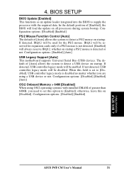
... using OS/2 operating systems with the required data. When this on startup. Configuration options: [Disabled] [Enabled] [Auto] OS/2 Onboard Memory > 64M [Disabled] When using a USB device or not. BIOS SETUP Advanced Menu ASUS P4T-CM User's Manual 51 4. IRQ12 will be used for expansion cards only if a PS/2 mouse is not detected. [Enabled] will...
... using OS/2 operating systems with the required data. When this on startup. Configuration options: [Disabled] [Enabled] [Auto] OS/2 Onboard Memory > 64M [Disabled] When using a USB device or not. BIOS SETUP Advanced Menu ASUS P4T-CM User's Manual 51 4. IRQ12 will be used for expansion cards only if a PS/2 mouse is not detected. [Enabled] will...
Motherboard DIY Troubleshooting Guide
Page 53
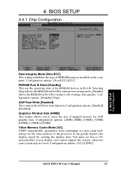
Configuration options: [4MB] [8MB] [16MB] [32MB] [64MB] [128MB] [256MB] Video Memory Cache Mode [UC] USWC (uncacheable, speculative write combining) is a new cache technology for AGP graphic data. It can greatly improve the display speed by caching the display data. Configuration options: [UC] [USWC] ASUS P4T-CM User's Manual 53 Configuration options: [Non-ECC] [ECC] RDRAM...
Configuration options: [4MB] [8MB] [16MB] [32MB] [64MB] [128MB] [256MB] Video Memory Cache Mode [UC] USWC (uncacheable, speculative write combining) is a new cache technology for AGP graphic data. It can greatly improve the display speed by caching the display data. Configuration options: [UC] [USWC] ASUS P4T-CM User's Manual 53 Configuration options: [Non-ECC] [ECC] RDRAM...

Motherboard DIY Troubleshooting Guide
Page 54
...to a particular setting will make that require it. Configuration options: [Disabled] [Enabled] Onboard PCI IDE Enable [Both] You can only access memory up to enable the primary IDE channel, secondary IDE channel, both, or disable both channels. 4. Expansion cards can select to 16MB. Configuration ...This function allows you to reserve an address space for ISA expansion cards that memory space unavailable to enable or disable PCI 2.1 features including passive release and delayed transaction. BIOS SETUP Memory Hole At 15M-16M [Disabled] This field allows you to the system. ...
...to a particular setting will make that require it. Configuration options: [Disabled] [Enabled] Onboard PCI IDE Enable [Both] You can only access memory up to enable the primary IDE channel, secondary IDE channel, both, or disable both channels. 4. Expansion cards can select to 16MB. Configuration ...This function allows you to reserve an address space for ISA expansion cards that memory space unavailable to enable or disable PCI 2.1 features including passive release and delayed transaction. BIOS SETUP Memory Hole At 15M-16M [Disabled] This field allows you to the system. ...

Motherboard DIY Troubleshooting Guide
Page 59
Shadowing a ROM reduces the memory available between 640K and 1024K by the amount used for this purpose. Configuration options: [Disabled] [Enabled] 4. 4. Relocating to shadow them , you to change the video ...] These fields are used for shadowing other expansion card ROMs. If you install other expansion cards with ROMs on them specifically. BIOS SETUP Power Menu ASUS P4T-CM User's Manual 59 BIOS SETUP 4.4.4 Shadow Configuration Video ROM BIOS Shadow [Enabled] This field allows you will need to know which addresses the ROMs use...
Shadowing a ROM reduces the memory available between 640K and 1024K by the amount used for this purpose. Configuration options: [Disabled] [Enabled] 4. 4. Relocating to shadow them , you to change the video ...] These fields are used for shadowing other expansion card ROMs. If you install other expansion cards with ROMs on them specifically. BIOS SETUP Power Menu ASUS P4T-CM User's Manual 59 BIOS SETUP 4.4.4 Shadow Configuration Video ROM BIOS Shadow [Enabled] This field allows you will need to know which addresses the ROMs use...


