User Guide
Page 3
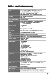
P4SD-LA specifications summary CPU Chipset Front Side Bus (FSB) Memory Expansion slots VGA Serial ATA IDE Audio LAN Special features Rear panel I/O Internal I/O BIOS features Industry standard Manageability Form factor Socket 478 for Intel® Pentium® 4 Northwood/Prescott On-die 512KB/... UltraDMA/150 SATA connectors 2 x UltraDMA 100/66/33 connectors RealTek ALC650 6-channel audio CODEC Realtek 8101L 10/100 Mbps Fast Ethernet controller Power Loss Restart ASUS EZ Flash 1 x Parallel port 1 x Serial port 1 x Video port 1 x PS/2 keyboard port 1 x PS/2 mouse port 4 x USB 2.0/USB 1.1 ports...
P4SD-LA specifications summary CPU Chipset Front Side Bus (FSB) Memory Expansion slots VGA Serial ATA IDE Audio LAN Special features Rear panel I/O Internal I/O BIOS features Industry standard Manageability Form factor Socket 478 for Intel® Pentium® 4 Northwood/Prescott On-die 512KB/... UltraDMA/150 SATA connectors 2 x UltraDMA 100/66/33 connectors RealTek ALC650 6-channel audio CODEC Realtek 8101L 10/100 Mbps Fast Ethernet controller Power Loss Restart ASUS EZ Flash 1 x Parallel port 1 x Serial port 1 x Video port 1 x PS/2 keyboard port 1 x PS/2 mouse port 4 x USB 2.0/USB 1.1 ports...
User Guide
Page 5
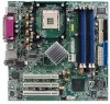
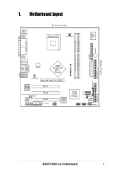
Motherboard layout PS/2 T: Mouse B: Keyboard COM1 24.5cm (9.64in) Socket 478 CPU_FAN1 Super I/O FLOPPY1 BUZZER P4SD-LA DDR DIMM1 (64/72 bit, 184-pin module) DDR DIMM2 (64/72 bit, 184-pin module) PARALLEL PORT VGA Bottom: USB1 USB2 Top: 1394 .../F PCI 2 Audio Codec PCI 3 CD_IN AUX SPEAKER OUT FRONT HP-OUT 1394 TI43AB22A 1394 PHY 01 23 BATTERY1 Intel ICH5 Chipset P31 P30 J19 4Mb BIOS USB2 USB1 HPANEL ATX Power Connector 24.5cm (9.64in) SECONDARY IDE PRIMARY IDE ASUS P4SD-LA motherboard 1 1.
Motherboard layout PS/2 T: Mouse B: Keyboard COM1 24.5cm (9.64in) Socket 478 CPU_FAN1 Super I/O FLOPPY1 BUZZER P4SD-LA DDR DIMM1 (64/72 bit, 184-pin module) DDR DIMM2 (64/72 bit, 184-pin module) PARALLEL PORT VGA Bottom: USB1 USB2 Top: 1394 .../F PCI 2 Audio Codec PCI 3 CD_IN AUX SPEAKER OUT FRONT HP-OUT 1394 TI43AB22A 1394 PHY 01 23 BATTERY1 Intel ICH5 Chipset P31 P30 J19 4Mb BIOS USB2 USB1 HPANEL ATX Power Connector 24.5cm (9.64in) SECONDARY IDE PRIMARY IDE ASUS P4SD-LA motherboard 1 1.
User Guide
Page 9
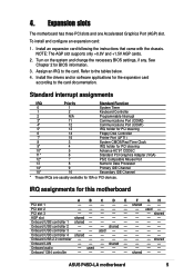
.... Assign an IRQ to the tables below. 4. Install the drivers and/or software applications for this motherboard A B C D E F GH PCI slot 1 - - - - - ASUS P4SD-LA motherboard 5 Onboard USB controller 3 - - used - To install and configure an expansion card: 1. IRQ... assignments for the expansion card according to the card documentation. Onboard audio - shared - - shared - - Turn on the system and change the necessary BIOS settings,...
.... Assign an IRQ to the tables below. 4. Install the drivers and/or software applications for this motherboard A B C D E F GH PCI slot 1 - - - - - ASUS P4SD-LA motherboard 5 Onboard USB controller 3 - - used - To install and configure an expansion card: 1. IRQ... assignments for the expansion card according to the card documentation. Onboard audio - shared - - shared - - Turn on the system and change the necessary BIOS settings,...
User Guide
Page 11
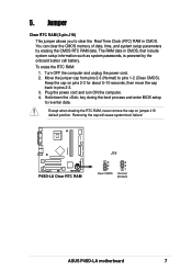
..., never remove the cap on pins 2-3 for about 5~10 seconds, then move the cap back to re-enter data. P4SD-LA P4SD-LA Clear RTC RAM J19 3 2 1 Clear CMOS 3 2 1 Normal (Default) ASUS P4SD-LA motherboard 7 The RAM data in CMOS. Keep the cap on jumper J19 default position. Removing the cap will cause system boot... computer and unplug the power cord. 2. Plug the power cord and turn ON the computer. 4. Hold down the key during the boot process and enter BIOS setup to pins 2-3. 3.
..., never remove the cap on pins 2-3 for about 5~10 seconds, then move the cap back to re-enter data. P4SD-LA P4SD-LA Clear RTC RAM J19 3 2 1 Clear CMOS 3 2 1 Normal (Default) ASUS P4SD-LA motherboard 7 The RAM data in CMOS. Keep the cap on jumper J19 default position. Removing the cap will cause system boot... computer and unplug the power cord. 2. Plug the power cord and turn ON the computer. 4. Hold down the key during the boot process and enter BIOS setup to pins 2-3. 3.
User Guide
Page 13
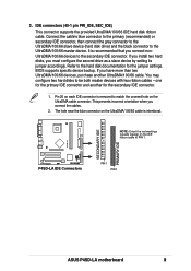
... UltraDMA/100/66 IDE hard disk ribbon cable. It is removed to the hard disk documentation for the secondary IDE connector. 1. BIOS supports specific device bootup. If you install two hard disks, you have more than two UltraDMA/100/66 devices, purchase another for... to match the covered hole on each IDE connector is recommended that you connect the cables. 2. P4SD-LA SECONDARY IDE PRIMARY IDE P4SD-LA IDE Connectors PIN 1 PIN 1 ASUS P4SD-LA motherboard 9 one for the primary IDE connector and another UltraDMA/100/66 cable. This prevents incorrect orientation when...
... UltraDMA/100/66 IDE hard disk ribbon cable. It is removed to the hard disk documentation for the secondary IDE connector. 1. BIOS supports specific device bootup. If you install two hard disks, you have more than two UltraDMA/100/66 devices, purchase another for... to match the covered hole on each IDE connector is recommended that you connect the cables. 2. P4SD-LA SECONDARY IDE PRIMARY IDE P4SD-LA IDE Connectors PIN 1 PIN 1 ASUS P4SD-LA motherboard 9 one for the primary IDE connector and another UltraDMA/100/66 cable. This prevents incorrect orientation when...
User Guide
Page 18
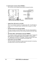
... or write activities of the device connected to the any of IDE connectors cause the IDE LED to light up when you turn on the BIOS or OS settings. 12. The LED lights up . • ATX Power Switch / Soft-Off Switch Lead (2-pin PWRBTN) This connector connects a switch ... OFF, depending on the system power, and blinks when the system is for rebooting the system without turning off the system power. 14 ASUS P4SD-LA motherboard System panel connector (20-pin HPANEL1) This connector accommodates several system front panel functions. ATX Power Power LED Switch* HPANEL PLED+ PLEDPWR GND...
... or write activities of the device connected to the any of IDE connectors cause the IDE LED to light up when you turn on the BIOS or OS settings. 12. The LED lights up . • ATX Power Switch / Soft-Off Switch Lead (2-pin PWRBTN) This connector connects a switch ... OFF, depending on the system power, and blinks when the system is for rebooting the system without turning off the system power. 14 ASUS P4SD-LA motherboard System panel connector (20-pin HPANEL1) This connector accommodates several system front panel functions. ATX Power Power LED Switch* HPANEL PLED+ PLEDPWR GND...


