P4S8X-MX English User Manaul E1997
Page 12
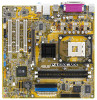
...chipsets, front side bus, memory and graphic interfaces. The SiS661GX chipset provides a high performance host interface for buying an ASUS® P4S8X-MX motherboard! The motherboard delivers a host of new features and latest technologies, making it , check the items in this motherboard... SiS661GX/964 chipset Embedded in your package with the list below. 1.2 Package contents Check your motherboard package for the following items. Motherboard ASUS P4S8X-MX motherboard Cables 1 x Serial ATA signal cable 1 x Serial ATA power cable 1 x Ultra DMA 133/100/66 cable Floppy disk drive...
...chipsets, front side bus, memory and graphic interfaces. The SiS661GX chipset provides a high performance host interface for buying an ASUS® P4S8X-MX motherboard! The motherboard delivers a host of new features and latest technologies, making it , check the items in this motherboard... SiS661GX/964 chipset Embedded in your package with the list below. 1.2 Package contents Check your motherboard package for the following items. Motherboard ASUS P4S8X-MX motherboard Cables 1 x Serial ATA signal cable 1 x Serial ATA power cable 1 x Ultra DMA 133/100/66 cable Floppy disk drive...

P4S8X-MX English User Manaul E1997
Page 13
... count, reduced voltage requirement, and up to fully support 10BASE-T/ 100BASE-TX Ethernet networking. The SATA specification allows for your multimedia and graphic-intensive applications. ASUS P4S8X-MX 1-3 See page 1-24. Serial ATA technology The motherboard supports the Serial ATA technology through the Serial ATA interfaces and the Intel® ICH6. The SiS964...
... count, reduced voltage requirement, and up to fully support 10BASE-T/ 100BASE-TX Ethernet networking. The SATA specification allows for your multimedia and graphic-intensive applications. ASUS P4S8X-MX 1-3 See page 1-24. Serial ATA technology The motherboard supports the Serial ATA technology through the Serial ATA interfaces and the Intel® ICH6. The SiS964...

P4S8X-MX English User Manaul E1997
Page 15
... should shut down the system and unplug the power cable before removing or plugging in any component, ensure that the system is switched off mode. P4S8X-MX P4S8X-MX Onboard LED SB_PWR ON Standby Power OFF Powered Off ASUS P4S8X-MX 1-5
... should shut down the system and unplug the power cable before removing or plugging in any component, ensure that the system is switched off mode. P4S8X-MX P4S8X-MX Onboard LED SB_PWR ON Standby Power OFF Powered Off ASUS P4S8X-MX 1-5

P4S8X-MX English User Manaul E1997
Page 17
1.5.2 Placement direction When installing the motherboard, make sure that you place it into the chassis in the image below. 1.5.3 Screw holes Place eight (8) screws into the holes indicated by circles to secure the motherboard to the rear part of the chassis P4S8X-MX ASUS P4S8X-MX 1-7 Do not overtighten the screws! Doing so can damage the motherboard. Place this side towards the rear of the chassis as indicated in the correct orientation. The edge with external ports goes to the chassis.
1.5.2 Placement direction When installing the motherboard, make sure that you place it into the chassis in the image below. 1.5.3 Screw holes Place eight (8) screws into the holes indicated by circles to secure the motherboard to the rear part of the chassis P4S8X-MX ASUS P4S8X-MX 1-7 Do not overtighten the screws! Doing so can damage the motherboard. Place this side towards the rear of the chassis as indicated in the correct orientation. The edge with external ports goes to the chassis.

P4S8X-MX English User Manaul E1997
Page 19
... CPU fits only in completely. 3. DO NOT force the CPU into the socket until it up to prevent bending the pins and damaging the CPU! ASUS P4S8X-MX 1-9 Unlock the socket by pressing the lever sideways, then lift it fits in place. Position the CPU above the socket such that the socket lever...
... CPU fits only in completely. 3. DO NOT force the CPU into the socket until it up to prevent bending the pins and damaging the CPU! ASUS P4S8X-MX 1-9 Unlock the socket by pressing the lever sideways, then lift it fits in place. Position the CPU above the socket such that the socket lever...

P4S8X-MX English User Manaul E1997
Page 21
CPU heatsink Retention module base ASUS P4S8X-MX 1-11 Place the heatsink on top of the installed CPU, making sure that the heatsink fits properly on the retention module base. • The retention ...
CPU heatsink Retention module base ASUS P4S8X-MX 1-11 Place the heatsink on top of the installed CPU, making sure that the heatsink fits properly on the retention module base. • The retention ...

P4S8X-MX English User Manaul E1997
Page 23
3. Push down the locks on the motherboard labeled CPU_FAN1. When secure, the retention locks should point to plug this connector. P4S8X-MX GND +12V Rotation 4. ASUS P4S8X-MX 1-13 Hardware monitoring errors can occur if you fail to opposite directions. CPU_FAN1 P4S8X-MX CPU fan connector Do not forget to the module base. When the fan and heatsink assembly is in place, connect the CPU fan cable to the connector on the retention mechanism to secure the heatsink and fan to connect the CPU fan connector!
3. Push down the locks on the motherboard labeled CPU_FAN1. When secure, the retention locks should point to plug this connector. P4S8X-MX GND +12V Rotation 4. ASUS P4S8X-MX 1-13 Hardware monitoring errors can occur if you fail to opposite directions. CPU_FAN1 P4S8X-MX CPU fan connector Do not forget to the module base. When the fan and heatsink assembly is in place, connect the CPU fan cable to the connector on the retention mechanism to secure the heatsink and fan to connect the CPU fan connector!

P4S8X-MX English User Manaul E1997
Page 25
... 3 • • HYB25D256800CE-6C 3 • • HYB25D256800BT-5B 3 • • V58C2256804SAT5 3 • • W942508CH-5 - •• K4H560838D-TCC4 3 •• NT5DS3232M8BT-5T 3 • • Legend: S S - ASUS P4S8X-MX 1-15 supports one pair of modules inserted into either slot, in a Single-channel memory configuration. DDR400* Qualified Vendors List DIMM support Size Vendor Model Brand...
... 3 • • HYB25D256800CE-6C 3 • • HYB25D256800BT-5B 3 • • V58C2256804SAT5 3 • • W942508CH-5 - •• K4H560838D-TCC4 3 •• NT5DS3232M8BT-5T 3 • • Legend: S S - ASUS P4S8X-MX 1-15 supports one pair of modules inserted into either slot, in a Single-channel memory configuration. DDR400* Qualified Vendors List DIMM support Size Vendor Model Brand...

P4S8X-MX English User Manaul E1997
Page 27
... In the future, you intend to use . 4. The following sub-sections describe the slots and the expansion cards that you may cause you removed earlier. 6. ASUS P4S8X-MX 1-17 Align the card connector with the screw you physical injury and damage motherboard components. 1.8.1 Installing an expansion card To install an expansion card: 1. Assign...
... In the future, you intend to use . 4. The following sub-sections describe the slots and the expansion cards that you may cause you removed earlier. 6. ASUS P4S8X-MX 1-17 Align the card connector with the screw you physical injury and damage motherboard components. 1.8.1 Installing an expansion card To install an expansion card: 1. Assign...

P4S8X-MX English User Manaul E1997
Page 29
This motherboard does not support 3.3V AGP cards. When you buy an AGP card, make sure that you ask for 1.5v P4S8X-MX Accelerated Graphics Port (AGP) P4S8X-MX ASUS P4S8X-MX 1-19 Note the notches on the card golden fingers to ensure that they fit the AGP slot on a PCI slot. 1.8.4 AGP slot The Accelerated Graphics ...
This motherboard does not support 3.3V AGP cards. When you buy an AGP card, make sure that you ask for 1.5v P4S8X-MX Accelerated Graphics Port (AGP) P4S8X-MX ASUS P4S8X-MX 1-19 Note the notches on the card golden fingers to ensure that they fit the AGP slot on a PCI slot. 1.8.4 AGP slot The Accelerated Graphics ...

P4S8X-MX English User Manaul E1997
Page 31
USBPW34 USBPW12 12 23 P4S8X-MX +5V (Default) +5VSB USBPW56 USBPW78 12 23 P4S8X-MX USB device wake up +5V (Default) +5VSB • The USB device wake-up . • The total current consumed must NOT exceed the power supply capability (+...5VSB) whether under normal condition or in low power mode) using the connected USB devices. The USBPW12 and USBPW34 jumpers are for each USB port; ASUS P4S8X-MX 1-21 otherwise, the system would not power up feature requires a power supply that you can provide 500mA on the +5VSB lead for the rear USB...
USBPW34 USBPW12 12 23 P4S8X-MX +5V (Default) +5VSB USBPW56 USBPW78 12 23 P4S8X-MX USB device wake up +5V (Default) +5VSB • The USB device wake-up . • The total current consumed must NOT exceed the power supply capability (+...5VSB) whether under normal condition or in low power mode) using the connected USB devices. The USBPW12 and USBPW34 jumpers are for each USB port; ASUS P4S8X-MX 1-21 otherwise, the system would not power up feature requires a power supply that you can provide 500mA on the +5VSB lead for the rear USB...

P4S8X-MX English User Manaul E1997
Page 33
... Line In Line Out Mic In 4-channel Rear Speaker Out Front Speaker Out Mic In 6-channel Rear Speaker Out Front Speaker Out Bass/Center Speaker ASUS P4S8X-MX 1-23 P a r a l l e l p o r t . L A N ( R J - 4 5 ) p o r t . 1.10 Connectors 1.10.1 Rear panel connectors 1 2 3 4 5 6 11 10 9 8 7 1 . This port allows connection to the audio configuration table below for a PS/2 mouse...
... Line In Line Out Mic In 4-channel Rear Speaker Out Front Speaker Out Mic In 6-channel Rear Speaker Out Front Speaker Out Bass/Center Speaker ASUS P4S8X-MX 1-23 P a r a l l e l p o r t . L A N ( R J - 4 5 ) p o r t . 1.10 Connectors 1.10.1 Rear panel connectors 1 2 3 4 5 6 11 10 9 8 7 1 . This port allows connection to the audio configuration table below for a PS/2 mouse...

P4S8X-MX English User Manaul E1997
Page 35
Insert one end of the cable to this connector, then connect the other end to prevent incorrect cable connection when using an FDD cable with a covered Pin 5. 1.10.2 Internal connectors 1 . Pin 5 on the floppy ribbon cable to PIN 1. Floppy disk drive connector (34-1 pin FLOPPY) This connector is removed to the signal connector at the back of the floppy disk drive. PIN 1 P4S8X-MX Floppy disk drive connector P4S8X-MX ASUS P4S8X-MX 1-25 FLOPPY NOTE: Orient the red markings on the connector is for the provided floppy disk drive (FDD) signal cable.
Insert one end of the cable to this connector, then connect the other end to prevent incorrect cable connection when using an FDD cable with a covered Pin 5. 1.10.2 Internal connectors 1 . Pin 5 on the floppy ribbon cable to PIN 1. Floppy disk drive connector (34-1 pin FLOPPY) This connector is removed to the signal connector at the back of the floppy disk drive. PIN 1 P4S8X-MX Floppy disk drive connector P4S8X-MX ASUS P4S8X-MX 1-25 FLOPPY NOTE: Orient the red markings on the connector is for the provided floppy disk drive (FDD) signal cable.

P4S8X-MX English User Manaul E1997
Page 37
... the standard parallel ATA with 133 MB/s (Ultra DMA/133) GND RSATA_RXN2 RSATA_RXP2 GND RSATA_TXN2 RSATA_TXP2 GND P4S8X-MX SATA2 GND RSATA_RXN1 RSATA_RXP1 GND RSATA_TXN1 RSATA_TXP1 GND P4S8X-MX SATA connectors SATA1 If you install SATA hard disk drives, you 're using Windows® 2000/XP ...drivers before using the Serial ATA connectors. Serial ATA Master/Slave connectors Connector SATA1 SATA2 Setting Master Slave Use Boot disk Data disk ASUS P4S8X-MX 1-27 Serial ATA connectors (7-pin SATA1, SATA2) These connectors are not available in this motherboard. • Make sure to page...
... the standard parallel ATA with 133 MB/s (Ultra DMA/133) GND RSATA_RXN2 RSATA_RXP2 GND RSATA_TXN2 RSATA_TXP2 GND P4S8X-MX SATA2 GND RSATA_RXN1 RSATA_RXP1 GND RSATA_TXN1 RSATA_TXP1 GND P4S8X-MX SATA connectors SATA1 If you install SATA hard disk drives, you 're using Windows® 2000/XP ...drivers before using the Serial ATA connectors. Serial ATA Master/Slave connectors Connector SATA1 SATA2 Setting Master Slave Use Boot disk Data disk ASUS P4S8X-MX 1-27 Serial ATA connectors (7-pin SATA1, SATA2) These connectors are not available in this motherboard. • Make sure to page...

P4S8X-MX English User Manaul E1997
Page 39
...-ROM, TV tuner, or MPEG card. Doing so will damage the motherboard! AUX CD (White) (Black) P4S8X-MX Left Audio Channel Ground Ground Right Audio Channel Left Audio Channel Ground Ground Right Audio Channel P4S8X-MX Internal audio connectors ASUS P4S8X-MX 1-29 USB connectors (10-1 pin USB56, USB78) These connectors are for USB 2.0 ports. Connect the...
...-ROM, TV tuner, or MPEG card. Doing so will damage the motherboard! AUX CD (White) (Black) P4S8X-MX Left Audio Channel Ground Ground Right Audio Channel Left Audio Channel Ground Ground Right Audio Channel P4S8X-MX Internal audio connectors ASUS P4S8X-MX 1-29 USB connectors (10-1 pin USB56, USB78) These connectors are for USB 2.0 ports. Connect the...

P4S8X-MX English User Manaul E1997
Page 41
P4S8X-MX +5V SPDIFOUT GND 10. Connect one end of the S/PDIF audio cable this connector and the other end to the S/PDIF module. SPDIF P4S8X-MX Digital Audio Connector The S/PDIF module is available for an optional S/PDIF audio module. ASUS P4S8X-MX 1-31 Digital audio connector (4-1 pin SPDIF) An onboard S/PDIF Out connector is purchased separately.
P4S8X-MX +5V SPDIFOUT GND 10. Connect one end of the S/PDIF audio cable this connector and the other end to the S/PDIF module. SPDIF P4S8X-MX Digital Audio Connector The S/PDIF module is available for an optional S/PDIF audio module. ASUS P4S8X-MX 1-31 Digital audio connector (4-1 pin SPDIF) An onboard S/PDIF Out connector is purchased separately.

P4S8X-MX English User Manaul E1997
Page 45
... download the latest BIOS file for the motherboard and rename the same to continue. 2. Insert the floppy disk that D: is your optical drive. Floppy found !" ASUS P4S8X-MX 2-3 Press , then follow screen instructions to P 4 S 8 X M X . Press + during the Power-On Self Tests (POST). When the correct BIOS ...floppy disk and using EZ Flash: 1. Copy the original or the latest motherboard BIOS file to the bootable floppy disk. 2.1.2 ASUS EZ Flash utility The ASUS EZ Flash feature allows you rename the BIOS file to a floppy disk, then restart the system. 3. Make sure that you...
... download the latest BIOS file for the motherboard and rename the same to continue. 2. Insert the floppy disk that D: is your optical drive. Floppy found !" ASUS P4S8X-MX 2-3 Press , then follow screen instructions to P 4 S 8 X M X . Press + during the Power-On Self Tests (POST). When the correct BIOS ...floppy disk and using EZ Flash: 1. Copy the original or the latest motherboard BIOS file to the bootable floppy disk. 2.1.2 ASUS EZ Flash utility The ASUS EZ Flash feature allows you rename the BIOS file to a floppy disk, then restart the system. 3. Make sure that you...

P4S8X-MX English User Manaul E1997
Page 47
... the file and starts updating the BIOS. Version 1.10 Copyright (C) 2002 American Megatrends, Inc. Write the BIOS filename on the bootable floppy disk. done A:\> ASUS P4S8X-MX 2-5 Reboot the system from the motherboard support CD to the bootable floppy disk you created earlier. 3. done Erasing flash .... Boot the system in DOS mode..., then at the DOS prompt. 2. Version 1.10 Copyright (C) 2002 American Megatrends, Inc. Visit the ASUS website (www.asus.com) and download the latest BIOS file for the motherboard.
... the file and starts updating the BIOS. Version 1.10 Copyright (C) 2002 American Megatrends, Inc. Write the BIOS filename on the bootable floppy disk. done A:\> ASUS P4S8X-MX 2-5 Reboot the system from the motherboard support CD to the bootable floppy disk you created earlier. 3. done Erasing flash .... Boot the system in DOS mode..., then at the DOS prompt. 2. Version 1.10 Copyright (C) 2002 American Megatrends, Inc. Visit the ASUS website (www.asus.com) and download the latest BIOS file for the motherboard.

P4S8X-MX English User Manaul E1997
Page 49
...BIOS file. Bad BIOS checksum. Floppy not found ! Starting BIOS recovery... Checking for floppy... Reading file "P4S8XMX.ROM". Checking for CD-ROM... Start flashing... ASUS P4S8X-MX 2-7 Doing so can cause system boot failure! 4. Starting BIOS recovery... When no floppy disk is found, the utility automatically checks the optical drive for floppy... this motherboard. The utility then updates the corrupted BIOS file. Completed. Restart the system after the utility completes the updating process. Visit the ASUS website (www.asus.com) to the optical drive. 3.
...BIOS file. Bad BIOS checksum. Floppy not found ! Starting BIOS recovery... Checking for floppy... Reading file "P4S8XMX.ROM". Checking for CD-ROM... Start flashing... ASUS P4S8X-MX 2-7 Doing so can cause system boot failure! 4. Starting BIOS recovery... When no floppy disk is found, the utility automatically checks the optical drive for floppy... this motherboard. The utility then updates the corrupted BIOS file. Completed. Restart the system after the utility completes the updating process. Visit the ASUS website (www.asus.com) to the optical drive. 3.

P4S8X-MX English User Manaul E1997
Page 51
ASUS P4S8X-MX 2-9 Launch the ASUS Update utility from the nearest you to avoid network drop-down menu, then click traffic, or click A u t o S e l e c t. N e x t. Select U p d a t e B I n t e r n e t option from the Windows® desktop by clicking S t a r t > P r o g r a m s > A S U S > A S U S U p d a t e > A S U S U p d a t e. The ASUS Update main window appears. 2. Select the ASUS FTP site t h e I O S f r o m 3. Updating the BIOS through the Internet To update the BIOS through the Internet: 1. Click N e x t.
ASUS P4S8X-MX 2-9 Launch the ASUS Update utility from the nearest you to avoid network drop-down menu, then click traffic, or click A u t o S e l e c t. N e x t. Select U p d a t e B I n t e r n e t option from the Windows® desktop by clicking S t a r t > P r o g r a m s > A S U S > A S U S U p d a t e > A S U S U p d a t e. The ASUS Update main window appears. 2. Select the ASUS FTP site t h e I O S f r o m 3. Updating the BIOS through the Internet To update the BIOS through the Internet: 1. Click N e x t.


