
Motherboard DIY Troubleshooting Guide
Page 1
Motherboard P4S800 User Guide
Motherboard P4S800 User Guide
Motherboard DIY Troubleshooting Guide
Page 3
Features Contents Notices v Safety information vi About this guide vii ASUS contact information viii P4S800 specifications summary ix Chapter 1: Product introduction 1.1 Welcome 1-2 1.2 Package contents 1-2 1.3 Motherboard components 1-3 1.4 Special Features 1-6 1.5 Motherboard layout 1-8 1.6 Before you proceed 1-9 1.7 Motherboard installation 1-9 1.7.1 Placement direction 1-9 1.7.2 Screw holes 1-10 1.8 Central Processing Unit (CPU 1-10 1.8.1 Overview 1-10 1.8.2 Installing the CPU 1-11 1.9 System memory 1-12 1.9.1 Overview 1-12...
Features Contents Notices v Safety information vi About this guide vii ASUS contact information viii P4S800 specifications summary ix Chapter 1: Product introduction 1.1 Welcome 1-2 1.2 Package contents 1-2 1.3 Motherboard components 1-3 1.4 Special Features 1-6 1.5 Motherboard layout 1-8 1.6 Before you proceed 1-9 1.7 Motherboard installation 1-9 1.7.1 Placement direction 1-9 1.7.2 Screw holes 1-10 1.8 Central Processing Unit (CPU 1-10 1.8.1 Overview 1-10 1.8.2 Installing the CPU 1-11 1.9 System memory 1-12 1.9.1 Overview 1-12...
Motherboard DIY Troubleshooting Guide
Page 6
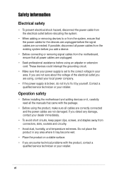
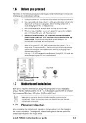
...are not sure about the voltage of the electrical outlet you add a device. • Before connecting or removing signal cables from the motherboard, ensure that all power cables are using, contact your dealer immediately. • To avoid short circuits, keep paper clips, screws, and... staples away from connectors, slots, sockets and circuitry. • Avoid dust, humidity, and temperature extremes. Operation safety • Before installing the motherboard and adding devices on a stable surface. • If you detect any damage, contact your local power company. • If the power supply...
...are not sure about the voltage of the electrical outlet you add a device. • Before connecting or removing signal cables from the motherboard, ensure that all power cables are using, contact your dealer immediately. • To avoid short circuits, keep paper clips, screws, and... staples away from connectors, slots, sockets and circuitry. • Avoid dust, humidity, and temperature extremes. Operation safety • Before installing the motherboard and adding devices on a stable surface. • If you detect any damage, contact your local power company. • If the power supply...

Motherboard DIY Troubleshooting Guide
Page 11
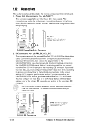
Chapter 1 This chapter describes the features of the layout, jumper settings, and connectors. It includes brief descriptions of the motherboard components, and illustrations of the P4S800 motherboard. Product introduction
Chapter 1 This chapter describes the features of the layout, jumper settings, and connectors. It includes brief descriptions of the motherboard components, and illustrations of the P4S800 motherboard. Product introduction
Motherboard DIY Troubleshooting Guide
Page 12
.../2700/2100/1600 DDR DIMMs, high-resolution graphics via an AGP 8X slot, USB 2.0 and 6-channel audio features, the P4S800 is damaged or missing, contact your P4S800 package for the following items. ASUS P4S800 motherboard ATX form factor: 12 in x 9.6 in a 478-pin package with Intel® Hyper-Threading Technology support coupled with... the unique MuTIOL technology to enter the world of the above items is your affordable vehicle to set a new benchmark for buying the ASUS® P4S800 motherboard! 1.1 Welcome! The ASUS P4S800 motherboard delivers a host of ASUS quality motherboards!
.../2700/2100/1600 DDR DIMMs, high-resolution graphics via an AGP 8X slot, USB 2.0 and 6-channel audio features, the P4S800 is damaged or missing, contact your P4S800 package for the following items. ASUS P4S800 motherboard ATX form factor: 12 in x 9.6 in a 478-pin package with Intel® Hyper-Threading Technology support coupled with... the unique MuTIOL technology to enter the world of the above items is your affordable vehicle to set a new benchmark for buying the ASUS® P4S800 motherboard! 1.1 Welcome! The ASUS P4S800 motherboard delivers a host of ASUS quality motherboards!
Motherboard DIY Troubleshooting Guide
Page 13
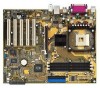
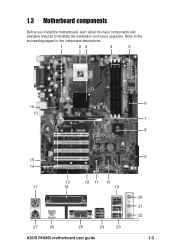
1.3 Motherboard components Before you install the motherboard, learn about its major components and available features to the succeeding pages for the component descriptions. 1 23 4 5 6 16 7 8 15 14 17 13 12 11 10 18 19 27 26 25 24 23 ASUS P4S800 motherboard user guide 9 20 21 22 1-3 Refer to facilitate the installation and future upgrades.
1.3 Motherboard components Before you install the motherboard, learn about its major components and available features to the succeeding pages for the component descriptions. 1 23 4 5 6 16 7 8 15 14 17 13 12 11 10 18 19 27 26 25 24 23 ASUS P4S800 motherboard user guide 9 20 21 22 1-3 Refer to facilitate the installation and future upgrades.
Motherboard DIY Troubleshooting Guide
Page 14
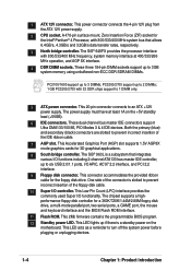
...) and secondary (black) connectors are slotted to 2 DIMMs; 1 GB PC3200/2700 with 800/533/400 MHz frequency, system memory interface at least 1A on the motherboard. This Low Pin Count (LPC) interface provides the commonly used Super I /O controller. These three 184-pin DIMM sockets support up to 3GB system memory using...
...) and secondary (black) connectors are slotted to 2 DIMMs; 1 GB PC3200/2700 with 800/533/400 MHz frequency, system memory interface at least 1A on the motherboard. This Low Pin Count (LPC) interface provides the commonly used Super I /O controller. These three 184-pin DIMM sockets support up to 3GB system memory using...
Motherboard DIY Troubleshooting Guide
Page 15
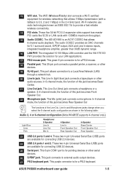
.... 16 LAN PHY. This Mic (pink) jack connects a microphone. These two 4-pin Universal Serial Bus (USB) ports are available for a PS/2 mouse. 18 Parallel port. ASUS P4S800 motherboard user guide 1-5 13 WiFi slot. The WiFi (Wireless Fidelity) slot connects a Wi-Fi certified equipment for pointing devices or other serial devices. 26 S/PDIF jack...
.... 16 LAN PHY. This Mic (pink) jack connects a microphone. These two 4-pin Universal Serial Bus (USB) ports are available for a PS/2 mouse. 18 Parallel port. ASUS P4S800 motherboard user guide 1-5 13 WiFi slot. The WiFi (Wireless Fidelity) slot connects a Wi-Fi certified equipment for pointing devices or other serial devices. 26 S/PDIF jack...
Motherboard DIY Troubleshooting Guide
Page 16
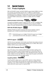
...the system and the BIOS would show the previous CPU parameter settings. ASUS motherboards now enable users to enjoy this protection feature without the need to overclocking. With a bus of the motherboard BIOS allows automatic resetting to the BIOS previous setting in case the system... for an optional ROM. 1-6 Chapter 1: Product introduction feature of 533MHz, AGP8X is indeed an incredible value for enhanced system performance. The ASUS P4S800 motherboard is twice as fast as AGP4X. PC3200/2700 support up to 2 DIMMs; 1 GB PC3200/2700 with high bandwidth speeds up to overclocking...
...the system and the BIOS would show the previous CPU parameter settings. ASUS motherboards now enable users to enjoy this protection feature without the need to overclocking. With a bus of the motherboard BIOS allows automatic resetting to the BIOS previous setting in case the system... for an optional ROM. 1-6 Chapter 1: Product introduction feature of 533MHz, AGP8X is indeed an incredible value for enhanced system performance. The ASUS P4S800 motherboard is twice as fast as AGP4X. PC3200/2700 support up to 2 DIMMs; 1 GB PC3200/2700 with high bandwidth speeds up to overclocking...
Motherboard DIY Troubleshooting Guide
Page 17
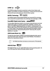
S/PDIF out The P4S800 provides convenient connectivity to 1GB/s. SoundMAX Digital Audio System can update BIOS before entering operating system. ASUS P4S800 motherboard user guide 1-7 MuTIOL Technology The P4S800 supports high-bandwidth DDR333 and unique MuTIOL technology that increases the ...bus speed between the northbridge and southbridge to external home theater audio systems via an S/PDIF out interface. ASUS EZ Flash With ASUS EZ...
S/PDIF out The P4S800 provides convenient connectivity to 1GB/s. SoundMAX Digital Audio System can update BIOS before entering operating system. ASUS P4S800 motherboard user guide 1-7 MuTIOL Technology The P4S800 supports high-bandwidth DDR333 and unique MuTIOL technology that increases the ...bus speed between the northbridge and southbridge to external home theater audio systems via an S/PDIF out interface. ASUS EZ Flash With ASUS EZ...

Motherboard DIY Troubleshooting Guide
Page 18
ATX Power Connector SEC_IDE PRI_IDE 30.5cm (12.0in) 1.5 Motherboard layout PS/2KBMS T: Mouse B: Keyboard SPDIF1 24.5cm (9.6in) Socket 478 DDR DIMM1 (64/72 bit,184-pin module) DDR DIMM2 (64/72 bit,184-... USBPW34 Bottom: USB3 USB4 Top: RJ-45 CPU_FAN ATX12V SiS 648FX Chip Top:Line In Center:Line Out Below:Mic In Accelerated Graphics Port (AGP) P4S800 ® PCI1 SiS 963LUA Chipset SPDIF_OUT FP_AUDIO CD AUX Audio Codec PCI2 PCI3 PCI4 CR2032 3V Lithium Cell CMOS Power CLRTC CHASSIS PCI5 WIFI USBPW56...
ATX Power Connector SEC_IDE PRI_IDE 30.5cm (12.0in) 1.5 Motherboard layout PS/2KBMS T: Mouse B: Keyboard SPDIF1 24.5cm (9.6in) Socket 478 DDR DIMM1 (64/72 bit,184-pin module) DDR DIMM2 (64/72 bit,184-... USBPW34 Bottom: USB3 USB4 Top: RJ-45 CPU_FAN ATX12V SiS 648FX Chip Top:Line In Center:Line Out Below:Mic In Accelerated Graphics Port (AGP) P4S800 ® PCI1 SiS 963LUA Chipset SPDIF_OUT FP_AUDIO CD AUX Audio Codec PCI2 PCI3 PCI4 CR2032 3V Lithium Cell CMOS Power CLRTC CHASSIS PCI5 WIFI USBPW56...
Motherboard DIY Troubleshooting Guide
Page 19
...as the power supply case, before touching any component, place it into it. The motherboard uses the ATX form factor that came with external ports goes to static electricity. 3. ASUS P4S800 motherboard user guide 1-9 Hold components by the edges to do so may cause severe damage ...to your chassis to ensure that the motherboard fits into the chassis in the bag that measures 12 inches x 9.6 inches...
...as the power supply case, before touching any component, place it into it. The motherboard uses the ATX form factor that came with external ports goes to static electricity. 3. ASUS P4S800 motherboard user guide 1-9 Hold components by the edges to do so may cause severe damage ...to your chassis to ensure that the motherboard fits into the chassis in the bag that measures 12 inches x 9.6 inches...

Motherboard DIY Troubleshooting Guide
Page 20
...supports 800/533/400MHz front side bus (FSB), and allows data transfer rates of the CPU into the holes indicated by circles to secure the motherboard to the chassis. Gold Mark 1-10 Incorrect installation of 6.4GB/s, 4.2GB/s and 3.2GB/s respectively. The socket is designed for the Intel&#...Pentium® 4 Processor in the illustration that should match a specific corner of the chassis 1.8 Central Processing Unit (CPU) 1.8.1 Overview The motherboard comes with 512/256KB L2 cache on one corner. Doing so may bend the pins and severely damage the CPU! Place this side towards the...
...supports 800/533/400MHz front side bus (FSB), and allows data transfer rates of the CPU into the holes indicated by circles to secure the motherboard to the chassis. Gold Mark 1-10 Incorrect installation of 6.4GB/s, 4.2GB/s and 3.2GB/s respectively. The socket is designed for the Intel&#...Pentium® 4 Processor in the illustration that should match a specific corner of the chassis 1.8 Central Processing Unit (CPU) 1.8.1 Overview The motherboard comes with 512/256KB L2 cache on one corner. Doing so may bend the pins and severely damage the CPU! Place this side towards the...
Motherboard DIY Troubleshooting Guide
Page 21
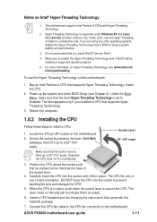
... steps to enable the Hyper-Threading Technology item in place, push down the socket lever to a 90°-100° angle. ASUS P4S800 motherboard user guide 1-11 Notes on Hyper-Threading Technology, visit www.intel.com/ info/hyperthreading. The item appears only if you installed a...and fan following the instructions that you are using any other operating systems, disable the Hyper-Threading Techonology item in one correct orientation. This motherboard supports Intel Pentium 4 CPUs with the heatsink package. 7. It is locked. 6. Install the CPU. 2. When the CPU is supported ...
... steps to enable the Hyper-Threading Technology item in place, push down the socket lever to a 90°-100° angle. ASUS P4S800 motherboard user guide 1-11 Notes on Hyper-Threading Technology, visit www.intel.com/ info/hyperthreading. The item appears only if you installed a...and fan following the instructions that you are using any other operating systems, disable the Hyper-Threading Techonology item in one correct orientation. This motherboard supports Intel Pentium 4 CPUs with the heatsink package. 7. It is locked. 6. Install the CPU. 2. When the CPU is supported ...
Motherboard DIY Troubleshooting Guide
Page 22
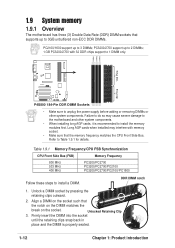
... when installed may cause severe damage to the motherboard and other system components. Align a DIMM on the socket such that the notch on the DIMM matches the break on the socket. DIMM1 DIMM2 DIMM3 80 Pins 104 Pins P4S800 ® P4S800 184-Pin DDR DIMM Sockets • Make ... memory frequency matches the CPU Front Side Bus. Unlock a DIMM socket by pressing the retaining clips outward. 2. 1.9 System memory 1.9.1 Overview The motherboard has three (3) Double Data Rate (DDR) DIMM sockets that supports up to 3GB unbuffered non-ECC DDR DIMMs. PC2100/1600 support up to 3 DIMMs;...
... when installed may cause severe damage to the motherboard and other system components. Align a DIMM on the socket such that the notch on the DIMM matches the break on the socket. DIMM1 DIMM2 DIMM3 80 Pins 104 Pins P4S800 ® P4S800 184-Pin DDR DIMM Sockets • Make ... memory frequency matches the CPU Front Side Bus. Unlock a DIMM socket by pressing the retaining clips outward. 2. 1.9 System memory 1.9.1 Overview The motherboard has three (3) Double Data Rate (DDR) DIMM sockets that supports up to 3GB unbuffered non-ECC DDR DIMMs. PC2100/1600 support up to 3 DIMMs;...
Motherboard DIY Troubleshooting Guide
Page 23
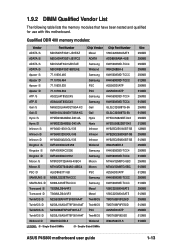
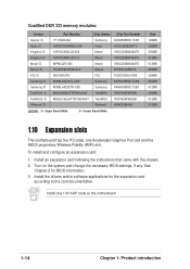
...512MB 256MB 512MB 128MB 256MB 512MB 256MB 256MB 512MB 256MB 512MB 512MB 256MB 512MB 256MB 512MB 256MB 512MB 256MB 512MB 512MB ASUS P4S800 motherboard user guide 1-13 1.9.2 DIMM Qualified Vendor List The following table lists the memory modules that have been tested and qualified for... use with this motherboard. Qualified DDR 400 memory modules: Vendor Part Number Chip Vendor Chip Part Number ADATA /S MDOMO5F3G31-JB1EAZ Mosel V58C2256804SAT5 ADATA /S MDOADHF3G31-...
...512MB 256MB 512MB 128MB 256MB 512MB 256MB 256MB 512MB 256MB 512MB 512MB 256MB 512MB 256MB 512MB 256MB 512MB 256MB 512MB 512MB ASUS P4S800 motherboard user guide 1-13 1.9.2 DIMM Qualified Vendor List The following table lists the memory modules that have been tested and qualified for... use with this motherboard. Qualified DDR 400 memory modules: Vendor Part Number Chip Vendor Chip Part Number ADATA /S MDOMO5F3G31-JB1EAZ Mosel V58C2256804SAT5 ADATA /S MDOADHF3G31-...
Motherboard DIY Troubleshooting Guide
Page 24
To install and configure an expansion card: 1. See Chapter 2 for the expansion card according to the card documentation. Turn on this motherboard! 1-14 Chapter 1: Product introduction Install only 1.5V AGP cards on the system and change the necessary BIOS settings, if any. Install an expansion card following ... W942508AH-6 LEGEND: /S - Single Sided DIMMs /D - Double Sided DIMMs Size 128MB 256MB 256MB 512MB 512MB 256MB 256MB 256MB 512MB 256MB 512MB 512MB 1.10 Expansion slots The motherboard has five PCI slots, one Accelerated Graphics Port slot and the...
To install and configure an expansion card: 1. See Chapter 2 for the expansion card according to the card documentation. Turn on this motherboard! 1-14 Chapter 1: Product introduction Install only 1.5V AGP cards on the system and change the necessary BIOS settings, if any. Install an expansion card following ... W942508AH-6 LEGEND: /S - Single Sided DIMMs /D - Double Sided DIMMs Size 128MB 256MB 256MB 512MB 512MB 256MB 256MB 256MB 512MB 256MB 512MB 512MB 1.10 Expansion slots The motherboard has five PCI slots, one Accelerated Graphics Port slot and the...
Motherboard DIY Troubleshooting Guide
Page 25
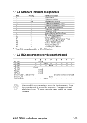
PCI slot 3 - - - Onboard USB 1.1/2.0 controller - - - - ASUS P4S800 motherboard user guide 1-15 1.10.1 Standard interrupt assignments IRQ Priority Standard Function 0 1 System Timer 1 2 Keyboard Controller 2 N/A Programmable... Processor 14* 9 Primary IDE Channel 15* 10 Secondary IDE Channel * These IRQs are usually available for ISA or PCI devices. 1.10.2 IRQ assignments for this motherboard A B C D E F GH PCI slot 1 - PCI slot 2 - - PCI slot 4 shared PCI slot 5 - Onboard Audio - - shared - - - - shared - - - - - - shared - - - - ...
PCI slot 3 - - - Onboard USB 1.1/2.0 controller - - - - ASUS P4S800 motherboard user guide 1-15 1.10.1 Standard interrupt assignments IRQ Priority Standard Function 0 1 System Timer 1 2 Keyboard Controller 2 N/A Programmable... Processor 14* 9 Primary IDE Channel 15* 10 Secondary IDE Channel * These IRQs are usually available for ISA or PCI devices. 1.10.2 IRQ assignments for this motherboard A B C D E F GH PCI slot 1 - PCI slot 2 - - PCI slot 4 shared PCI slot 5 - Onboard Audio - - shared - - - - shared - - - - - - shared - - - - ...
Motherboard DIY Troubleshooting Guide
Page 27
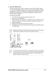
... position. Except when clearing the RTC RAM, never remove the cap on pins 2-3 for about 5~10 seconds, then move the cap back to pins 2-3. P4S800 ® P4S800 Clear RTC RAM CLRTC 12 Normal (Default) 23 Clear CMOS You do not need to clear the RTC when the system hangs due to overclocking... OFF the computer and unplug the power cord. 2. Plug the power cord and turn ON the computer. 6. Removing the cap will cause system boot failure! ASUS P4S800 motherboard user guide 1-17 To erase the RTC RAM: 1. 2.
... position. Except when clearing the RTC RAM, never remove the cap on pins 2-3 for about 5~10 seconds, then move the cap back to pins 2-3. P4S800 ® P4S800 Clear RTC RAM CLRTC 12 Normal (Default) 23 Clear CMOS You do not need to clear the RTC when the system hangs due to overclocking... OFF the computer and unplug the power cord. 2. Plug the power cord and turn ON the computer. 6. Removing the cap will cause system boot failure! ASUS P4S800 motherboard user guide 1-17 To erase the RTC RAM: 1. 2.
Motherboard DIY Troubleshooting Guide
Page 28
...non-UltraDMA133/100/66 devices to prevent incorrect insertion when using ribbon cables with two ribbon cables - P4S800 ® NOTE: Orient the red markings (usually zigzag) on the motherboard. 1. After connecting one for the jumper settings. It is removed to match the covered hole on... the floppy ribbon cable to PIN 1. SEC_IDE PRI_IDE P4S800 IDE Connectors 1-18 PIN 1 Chapter 1: Product introduction If you ...
...non-UltraDMA133/100/66 devices to prevent incorrect insertion when using ribbon cables with two ribbon cables - P4S800 ® NOTE: Orient the red markings (usually zigzag) on the motherboard. 1. After connecting one for the jumper settings. It is removed to match the covered hole on... the floppy ribbon cable to PIN 1. SEC_IDE PRI_IDE P4S800 IDE Connectors 1-18 PIN 1 Chapter 1: Product introduction If you ...


