
Motherboard DIY Troubleshooting Guide
Page 1
P4S533-MX Motherboard
P4S533-MX Motherboard

P4S533-MX User Manual
Page 11
Chapter 1 This chapter describes the features of the layout, jumper settings, and connectors. It includes brief descriptions of the motherboard components, and illustrations of the P4S533-MX motherboard. Product introduction
Chapter 1 This chapter describes the features of the layout, jumper settings, and connectors. It includes brief descriptions of the motherboard components, and illustrations of the P4S533-MX motherboard. Product introduction
P4S533-MX User Manual
Page 12
...478-pin package coupled with the list below. 1.2 Package contents Check your P4S533-MX package for the following items. ASUS P4S533-MX motherboard ATX form factor: 9.6 in x 9.6 in (24.5 cm x 24.5 cm) ASUS P4S533-MX series support CD 80-conductor UltraDMA/66/100 IDE cable Ribbon cable for... solution. 1.1 Welcome! Thank you start installing the motherboard, and hardware devices on it another standout in your package with the SiS® 651 chipset to enter the world of ASUS quality motherboards! The ASUS P4S533-MX motherboard delivers a host of new features and latest technologies ...
...478-pin package coupled with the list below. 1.2 Package contents Check your P4S533-MX package for the following items. ASUS P4S533-MX motherboard ATX form factor: 9.6 in x 9.6 in (24.5 cm x 24.5 cm) ASUS P4S533-MX series support CD 80-conductor UltraDMA/66/100 IDE cable Ribbon cable for... solution. 1.1 Welcome! Thank you start installing the motherboard, and hardware devices on it another standout in your package with the SiS® 651 chipset to enter the world of ASUS quality motherboards! The ASUS P4S533-MX motherboard delivers a host of new features and latest technologies ...
P4S533-MX User Manual
Page 13
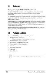
Refer to facilitate the installation and future upgrades. 1.3 Motherboard components Before you install the motherboard, learn about its major components and available features to the succeeding pages for the component descriptions. 1 2 34 56 16 15 14 13 12 17 18 11 19 27 26 25 24 23 ASUS P4S533-MX motherboard user guide 7 8 9 10 20 21 22 1-3
Refer to facilitate the installation and future upgrades. 1.3 Motherboard components Before you install the motherboard, learn about its major components and available features to the succeeding pages for the component descriptions. 1 2 34 56 16 15 14 13 12 17 18 11 19 27 26 25 24 23 ASUS P4S533-MX motherboard user guide 7 8 9 10 20 21 22 1-3
P4S533-MX User Manual
Page 15
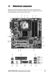
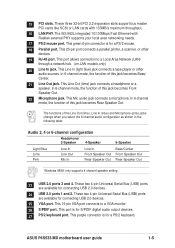
... S/PDIF port. This 15-pin VGA port connects to a Local Area Network (LAN) through a network hub. (on LAN models only) 20 Line In jack. ASUS P4S533-MX motherboard user guide 1-5 15 PCI slots. These three 32-bit PCI 2.2 expansion slots support bus master PCI cards like SCSI or LAN cards with Realtek external...
... S/PDIF port. This 15-pin VGA port connects to a Local Area Network (LAN) through a network hub. (on LAN models only) 20 Line In jack. ASUS P4S533-MX motherboard user guide 1-5 15 PCI slots. These three 32-bit PCI 2.2 expansion slots support bus master PCI cards like SCSI or LAN cards with Realtek external...
P4S533-MX User Manual
Page 16
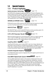
... FMB2 power design that support up to pay for business professionals, audiophiles, musicians, and gamers. Powerful Integrated Graphics The P4S533-MX delivers powerful integrated 2D and 3D graphics performance for each parameter. SoundMAX Digital Audio System (page 3-3) The SoundMax ...DirectSound 3D™, A3D, MacroFX, ZoomFX, MultiDrive 5.1 and EAX. 1-6 Chapter 1: Product introduction Unlike other competing vendors' products, ASUS motherboards now enable users to enjoy this protection feature without the need to open the case to restore BIOS data from a floppy diskette even...
... FMB2 power design that support up to pay for business professionals, audiophiles, musicians, and gamers. Powerful Integrated Graphics The P4S533-MX delivers powerful integrated 2D and 3D graphics performance for each parameter. SoundMAX Digital Audio System (page 3-3) The SoundMax ...DirectSound 3D™, A3D, MacroFX, ZoomFX, MultiDrive 5.1 and EAX. 1-6 Chapter 1: Product introduction Unlike other competing vendors' products, ASUS motherboards now enable users to enjoy this protection feature without the need to open the case to restore BIOS data from a floppy diskette even...
P4S533-MX User Manual
Page 17
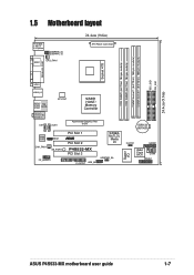
...DIMM Socket 1 (64/72-bit, 168-pin module) DIMM Socket 1 (64/72-bit, 168-pin module) SEC_IDE1 PRI_IDE1 24.4cm (9.6in) 1.5 Motherboard layout PS/2KBMS T: Mouse B: Keyboard USBPWR_34 USBPWR_12 SPDIF1 CPU_FAN1 24.4cm (9.6in) ATX Power Connector PARALLEL PORT VGA1 USB20_12 Bottom: USB3 USB4 Top: ...23 01 23 CR2032 3V Lithium Cell CMOS Power Audio Codec MDC1 CHA_FAN1 SB_PWR1 FP_AUDIO1 PCI Slot 1 ® PCI Slot 2 P4S533-MX PCI Slot 3 FLOPPY1 USB_56 SiS962L MuTLOL Media I/0 USBPWR_56 Super I/O CLRTC1 GAME1 2Mbit Flash BIOS COM1 PANEL1 ASUS P4S533-MX motherboard user guide 1-7
...DIMM Socket 1 (64/72-bit, 168-pin module) DIMM Socket 1 (64/72-bit, 168-pin module) SEC_IDE1 PRI_IDE1 24.4cm (9.6in) 1.5 Motherboard layout PS/2KBMS T: Mouse B: Keyboard USBPWR_34 USBPWR_12 SPDIF1 CPU_FAN1 24.4cm (9.6in) ATX Power Connector PARALLEL PORT VGA1 USB20_12 Bottom: USB3 USB4 Top: ...23 01 23 CR2032 3V Lithium Cell CMOS Power Audio Codec MDC1 CHA_FAN1 SB_PWR1 FP_AUDIO1 PCI Slot 1 ® PCI Slot 2 P4S533-MX PCI Slot 3 FLOPPY1 USB_56 SiS962L MuTLOL Media I/0 USBPWR_56 Super I/O CLRTC1 GAME1 2Mbit Flash BIOS COM1 PANEL1 ASUS P4S533-MX motherboard user guide 1-7
P4S533-MX User Manual
Page 19
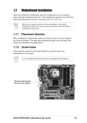
... the rear of your chassis to do so may damage the motherboard. Doing so may cause you physical injury and damage motherboard components. 1.7.1 Placement direction When installing the motherboard, make sure that you install the motherboard, study the configuration of the chassis ASUS P4S533-MX motherboard user guide 1-9 Do not overtighten the screws! The edge with external...
... the rear of your chassis to do so may damage the motherboard. Doing so may cause you physical injury and damage motherboard components. 1.7.1 Placement direction When installing the motherboard, make sure that you install the motherboard, study the configuration of the chassis ASUS P4S533-MX motherboard user guide 1-9 Do not overtighten the screws! The edge with external...
P4S533-MX User Manual
Page 21
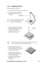
...angle. Connect the CPU fan cable to secure the CPU. When the CPU is in one correct orientation. ASUS P4S533-MX motherboard user guide 1-11 Locate the 478-pin ZIF socket on the motherboard. Gold Mark The CPU fits only in place, push down the socket lever to the CPU_FAN1 connector on... the motherboard. 2. 1.8.2 Installing the CPU Follow these steps to indicate that it is locked. 6. The lever clicks on the side...
...angle. Connect the CPU fan cable to secure the CPU. When the CPU is in one correct orientation. ASUS P4S533-MX motherboard user guide 1-11 Locate the 478-pin ZIF socket on the motherboard. Gold Mark The CPU fits only in place, push down the socket lever to the CPU_FAN1 connector on... the motherboard. 2. 1.8.2 Installing the CPU Follow these steps to indicate that it is locked. 6. The lever clicks on the side...
P4S533-MX User Manual
Page 23
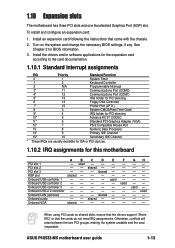
shared - - ASUS P4S533-MX motherboard user guide 1-13 shared - - F - - - - - used - - - When using PCI cards on the system and change the necessary BIOS settings, if any. Turn on shared slots, ensure that the drivers support "Share IRQ" or that came with the chassis. 2. See Chapter 2 for this motherboard A B C ...USB controller 3 - - - - - GH used - - To install and configure an expansion card: 1. 1.10 Expansion slots The motherboard has three PCI slots and one Accelerated Graphics Port (AGP) slot. AGP slot shared - - - - Onboard VGA shared - - - -
shared - - ASUS P4S533-MX motherboard user guide 1-13 shared - - F - - - - - used - - - When using PCI cards on the system and change the necessary BIOS settings, if any. Turn on shared slots, ensure that the drivers support "Share IRQ" or that came with the chassis. 2. See Chapter 2 for this motherboard A B C ...USB controller 3 - - - - - GH used - - To install and configure an expansion card: 1. 1.10 Expansion slots The motherboard has three PCI slots and one Accelerated Graphics Port (AGP) slot. AGP slot shared - - - - Onboard VGA shared - - - -

P4S533-MX User Manual
Page 25
Removing the cap will cause system boot failure! ® P4S533-MX CLRTC1 12 23 Normal (Default) Clear CMOS P4S533-MX Clear RTC RAM Setting You do not need to clear the RTC when the system hangs due to overclocking, use the C.P.R. (CPU Parameter Recall) ... Real Time Clock (RTC) RAM in CMOS, that include system setup information such as system passwords, is powered by erasing the CMOS RTC RAM data. ASUS P4S533-MX motherboard user guide 1-15 2. The RAM data in CMOS. Move the jumper cap from pins 1-2 (default) to default values. Clear RTC RAM (CLRTC1) This jumper...
Removing the cap will cause system boot failure! ® P4S533-MX CLRTC1 12 23 Normal (Default) Clear CMOS P4S533-MX Clear RTC RAM Setting You do not need to clear the RTC when the system hangs due to overclocking, use the C.P.R. (CPU Parameter Recall) ... Real Time Clock (RTC) RAM in CMOS, that include system setup information such as system passwords, is powered by erasing the CMOS RTC RAM data. ASUS P4S533-MX motherboard user guide 1-15 2. The RAM data in CMOS. Move the jumper cap from pins 1-2 (default) to default values. Clear RTC RAM (CLRTC1) This jumper...
P4S533-MX User Manual
Page 27
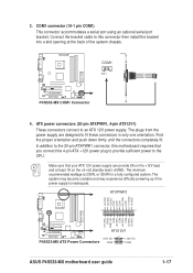
Connect the bracket cable to this motherboard requires that your ATX 12V power supply can provide 8A on the +12V lead and at the back of the system chassis. ATX power connectors (... -12.0VDC +3.3VDC +12.0VDC +5VSB PWR_OK COM +5.0VDC COM +5.0VDC COM +3.3VDC +3.3VDC ® P4S533-MX ATX12V1 +12V DC P4S533-MX ATX Power Connectors COM +12V DC COM ASUS P4S533-MX motherboard user guide 1-17 COM1 PIN 1 ® P4S533-MX P4S533-MX COM1 Connector 4. 3. The plugs from the power supply are designed to an ATX 12V...
Connect the bracket cable to this motherboard requires that your ATX 12V power supply can provide 8A on the +12V lead and at the back of the system chassis. ATX power connectors (... -12.0VDC +3.3VDC +12.0VDC +5VSB PWR_OK COM +5.0VDC COM +5.0VDC COM +3.3VDC +3.3VDC ® P4S533-MX ATX12V1 +12V DC P4S533-MX ATX Power Connectors COM +12V DC COM ASUS P4S533-MX motherboard user guide 1-17 COM1 PIN 1 ® P4S533-MX P4S533-MX COM1 Connector 4. 3. The plugs from the power supply are designed to an ATX 12V...

P4S533-MX User Manual
Page 29
... 2.0 specification that support the next generation USB peripherals such as high resolution cameras, scanners, and printers. USB+6V USB_P6USB_P6+ GND NC ® P4S533-MX P4S533-MX USB 2.0 Header USB56 (Blue) 1 USB+5V USB_P5USB_P5+ GND 8. Front panel audio connector (10-1 pin FP_AUDIO1) This is purchased separately....USB ports. 7. The module has two USB 2.0 ports that supports up to this header. AGND +5VA BLINE_OUT_R BLINE_OUT_L ® P4S533-MX FP_AUDIO1 P4S533-MX Front Panel Audio Connector ASUS P4S533-MX motherboard user guide MIC2 MICPWR Line out_R NC Line out_L 1-19
... 2.0 specification that support the next generation USB peripherals such as high resolution cameras, scanners, and printers. USB+6V USB_P6USB_P6+ GND NC ® P4S533-MX P4S533-MX USB 2.0 Header USB56 (Blue) 1 USB+5V USB_P5USB_P5+ GND 8. Front panel audio connector (10-1 pin FP_AUDIO1) This is purchased separately....USB ports. 7. The module has two USB 2.0 ports that supports up to this header. AGND +5VA BLINE_OUT_R BLINE_OUT_L ® P4S533-MX FP_AUDIO1 P4S533-MX Front Panel Audio Connector ASUS P4S533-MX motherboard user guide MIC2 MICPWR Line out_R NC Line out_L 1-19
P4S533-MX User Manual
Page 31
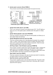
... system without turning off the system power. • Hard Disk Activity Lead (2-pin IDE_LED) This connector supplies power to the system power LED. P4S533-MX System Panel Connectors • System Power LED Lead (3-1 pin PLED) This 3-1 pin connector connects to the hard disk activity LED. Ground ... power supply. Attach the casemounted suspend switch to this LED to light up when you turn on the BIOS or OS settings. ASUS P4S533-MX motherboard user guide 1-21 The read or write activities of any device connected to expand the life of certain system components. System panel ...
... system without turning off the system power. • Hard Disk Activity Lead (2-pin IDE_LED) This connector supplies power to the system power LED. P4S533-MX System Panel Connectors • System Power LED Lead (3-1 pin PLED) This 3-1 pin connector connects to the hard disk activity LED. Ground ... power supply. Attach the casemounted suspend switch to this LED to light up when you turn on the BIOS or OS settings. ASUS P4S533-MX motherboard user guide 1-21 The read or write activities of any device connected to expand the life of certain system components. System panel ...

P4S533-MX User Manual
Page 35
... above prompt, type Y to update the main BIOS area. Press Y to continue with the new BIOS. Flash Memory: SST 49LF004 Update Main BIOS area (Y/N)? _ 7. ASUS P4S533-MX motherboard user guide 2-3 Press to remove the message, then type in the BIOS file name that you downloaded from the... ASUS website, then press . DO NOT shutdown or reset the system while updating the BIOS area! Press . 6. 5. At the prompt, "Please Enter File Name for ...
... above prompt, type Y to update the main BIOS area. Press Y to continue with the new BIOS. Flash Memory: SST 49LF004 Update Main BIOS area (Y/N)? _ 7. ASUS P4S533-MX motherboard user guide 2-3 Press to remove the message, then type in the BIOS file name that you downloaded from the... ASUS website, then press . DO NOT shutdown or reset the system while updating the BIOS area! Press . 6. 5. At the prompt, "Please Enter File Name for ...
P4S533-MX User Manual
Page 37
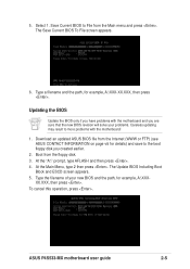
... prompt, type AFLASH and then press . 4. Type the filename of your problems. Careless updating may result to File from the floppy disk. 3. ASUS P4S533-MX motherboard user guide 2-5 At the Main Menu, type 2 then press . Save Current BIOS to more problems with the... motherboard and you have problems with the motherboard! 1. The Save Current BIOS To File screen appears. 6. Download an updated ASUS BIOS file from the Internet (WWW or FTP) (see ASUS CONTACT INFORMATION on page viii for example, A:\XXX-XX.XXX,...
... prompt, type AFLASH and then press . 4. Type the filename of your problems. Careless updating may result to File from the floppy disk. 3. ASUS P4S533-MX motherboard user guide 2-5 At the Main Menu, type 2 then press . Save Current BIOS to more problems with the... motherboard and you have problems with the motherboard! 1. The Save Current BIOS To File screen appears. 6. Download an updated ASUS BIOS file from the Internet (WWW or FTP) (see ASUS CONTACT INFORMATION on page viii for example, A:\XXX-XX.XXX,...
P4S533-MX User Manual
Page 39
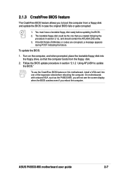
...2.1.3 CrashFree BIOS feature The CrashFree BIOS feature allows you to update the BIOS." Turn on this motherboard, install a VGA card into the floppy drive, so that you reboot the computer. ASUS P4S533-MX motherboard user guide 2-7 Follow the BIOS update procedure in case the original BIOS fails or gets corrupted.... disk and update the BIOS in section "2.1.2 Using AFLASH to boot the computer from the floppy disk. 2. On motherboards with onboard VGA, such as the P4S533-MX, you will not see the screen display when the BIOS crashes even if you created following the procedure in ...
...2.1.3 CrashFree BIOS feature The CrashFree BIOS feature allows you to update the BIOS." Turn on this motherboard, install a VGA card into the floppy drive, so that you reboot the computer. ASUS P4S533-MX motherboard user guide 2-7 Follow the BIOS update procedure in case the original BIOS fails or gets corrupted.... disk and update the BIOS in section "2.1.2 Using AFLASH to boot the computer from the floppy disk. 2. On motherboards with onboard VGA, such as the P4S533-MX, you will not see the screen display when the BIOS crashes even if you created following the procedure in ...
P4S533-MX User Manual
Page 41
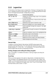
... keys and their corresponding functions. Scroll bar When a scroll bar appears to the right of the Setup screen is more information to the last page. ASUS P4S533-MX motherboard user guide 2-9 2.2.2 Legend bar At the bottom of a help window, it indicates that will not fit in the BIOS Setup Jumps to the Exit...
... keys and their corresponding functions. Scroll bar When a scroll bar appears to the right of the Setup screen is more information to the last page. ASUS P4S533-MX motherboard user guide 2-9 2.2.2 Legend bar At the bottom of a help window, it indicates that will not fit in the BIOS Setup Jumps to the Exit...
P4S533-MX User Manual
Page 43
... ignored. To confirm the password, type the password again and press . Forgot the password? Refer to section "1.11.2 Clear RTC RAM" on a 3.5-inch diskette. ASUS P4S533-MX motherboard user guide 2-11 Type in the Main menu. The same dialog box as opposed to eight alphanumeric characters. A note about 2 seconds, then power up to...
... ignored. To confirm the password, type the password again and press . Forgot the password? Refer to section "1.11.2 Clear RTC RAM" on a 3.5-inch diskette. ASUS P4S533-MX motherboard user guide 2-11 Type in the Main menu. The same dialog box as opposed to eight alphanumeric characters. A note about 2 seconds, then power up to...
P4S533-MX User Manual
Page 45
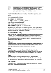
... hard disk. To make changes to this field, set the Type field to [User Type HDD] and the Translation Method field to the Main menu. ASUS P4S533-MX motherboard user guide 2-13 This is installed or if you are : [CD-ROM] - If no drive is necessary so that you configured. After entering the...
... hard disk. To make changes to this field, set the Type field to [User Type HDD] and the Translation Method field to the Main menu. ASUS P4S533-MX motherboard user guide 2-13 This is installed or if you are : [CD-ROM] - If no drive is necessary so that you configured. After entering the...


