P4S533-MX User Manual
Page 3
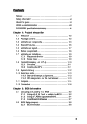
... (CPU 1-10 1.8.1 Overview 1-11 1.8.2 Installing the CPU 1-11 1.9 System memory 1-12 1.10 Expansion slots 1-13 1.10.1 Standard interrupt assignments 1-13 1.10.1 IRQ assignments for this motherboard 1-13 1.11 Jumpers 1-14 1.12 Connectors 1-16 Chapter 2: BIOS information 2.1 Managing and updating your BIOS 2-2 2.1.1 Using ASUS EZ Flash to update the BIOS 2-2 2.1.2 Using AFLASH to...
... (CPU 1-10 1.8.1 Overview 1-11 1.8.2 Installing the CPU 1-11 1.9 System memory 1-12 1.10 Expansion slots 1-13 1.10.1 Standard interrupt assignments 1-13 1.10.1 IRQ assignments for this motherboard 1-13 1.11 Jumpers 1-14 1.12 Connectors 1-16 Chapter 2: BIOS information 2.1 Managing and updating your BIOS 2-2 2.1.1 Using ASUS EZ Flash to update the BIOS 2-2 2.1.2 Using AFLASH to...
P4S533-MX User Manual
Page 9
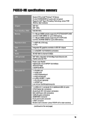
... 2 x 184-pin DIMM sockets support for PC2700/2100/PC1600 non-ECC DDR DIMMs for up to 2GB memory 2 x 168-pin DIMM sockets support for PC133/PC100 non-ECC SDRAM DIMM for up to 2GB memory 1 x AGP 4X (1.5V only) 3 x PCI Integrated 3D graphics controller in SiS 651 chipset 2 x UltraDMA 133/100.../66/33 connectors ADI AD1980 6-channel CODEC SiS® 962L integrated 10/100 Mbps Fast Ethernet with Realtek external PHY Power Loss Restart Digital audio via an S/PDIF Out inteface ASUS EZ ...
... 2 x 184-pin DIMM sockets support for PC2700/2100/PC1600 non-ECC DDR DIMMs for up to 2GB memory 2 x 168-pin DIMM sockets support for PC133/PC100 non-ECC SDRAM DIMM for up to 2GB memory 1 x AGP 4X (1.5V only) 3 x PCI Integrated 3D graphics controller in SiS 651 chipset 2 x UltraDMA 133/100.../66/33 connectors ADI AD1980 6-channel CODEC SiS® 962L integrated 10/100 Mbps Fast Ethernet with Realtek external PHY Power Loss Restart Digital audio via an S/PDIF Out inteface ASUS EZ ...
P4S533-MX User Manual
Page 12
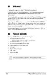
Before you for buying the ASUS® P4S533-MX motherboard! 1.1 Welcome! Supporting up to 2GB of system memory with the PC2700/2100/1600 DDR DIMMs or the PC133/PC100 SDRAM DIMMs, high-resolution graphics via an AGP 4X slot, USB 2.0, and 6-channel audio ... of new features and latest technologies making it , check the items in your package with the SiS® 651 chipset to enter the world of ASUS quality motherboards! The motherboard incorporates the Intel® Pentium® 4 Processor in the long line of computing! Thank you start installing the motherboard, and hardware...
Before you for buying the ASUS® P4S533-MX motherboard! 1.1 Welcome! Supporting up to 2GB of system memory with the PC2700/2100/1600 DDR DIMMs or the PC133/PC100 SDRAM DIMMs, high-resolution graphics via an AGP 4X slot, USB 2.0, and 6-channel audio ... of new features and latest technologies making it , check the items in your package with the SiS® 651 chipset to enter the world of ASUS quality motherboards! The motherboard incorporates the Intel® Pentium® 4 Processor in the long line of computing! Thank you start installing the motherboard, and hardware...

P4S533-MX User Manual
Page 14
... stereo inputs, integrated headphone amplifier, greater than 90dB dynamic range. 1-4 Chapter 1: Product introduction This LED lights up to 2GB system memory using unbuffered non-ECC PC133/PC100 SDRAM DIMMs. 7 IDE connectors. This 20-pin connector connects to prevent incorrect insertion of the IDE... PCI Bridge. 10 Flash ROM. A 478-pin surface mount, Zero Insertion Force (ZIF) socket for the Intel Pentium 4 processor, a memory controller and SiS MuTIOL technology. 3 CPU socket. This LED acts as the SiS962L MuTIOL Media I/O, this controller integrates the audio controller with ...
... stereo inputs, integrated headphone amplifier, greater than 90dB dynamic range. 1-4 Chapter 1: Product introduction This LED lights up to 2GB system memory using unbuffered non-ECC PC133/PC100 SDRAM DIMMs. 7 IDE connectors. This 20-pin connector connects to prevent incorrect insertion of the IDE... PCI Bridge. 10 Flash ROM. A 478-pin surface mount, Zero Insertion Force (ZIF) socket for the Intel Pentium 4 processor, a memory controller and SiS MuTIOL technology. 3 CPU socket. This LED acts as the SiS962L MuTIOL Media I/O, this controller integrates the audio controller with ...
P4S533-MX User Manual
Page 17
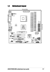
... T: Mouse B: Keyboard USBPWR_34 USBPWR_12 SPDIF1 CPU_FAN1 24.4cm (9.6in) ATX Power Connector PARALLEL PORT VGA1 USB20_12 Bottom: USB3 USB4 Top: RJ-45 ATX12V1 SiS651 HOST/ Memory Controller Top:Line In Center:Line Out Below:Mic In CD1 AUX1 Accelerated Graphics Port (AGP) 01 23 01 23 CR2032 3V Lithium Cell CMOS... SB_PWR1 FP_AUDIO1 PCI Slot 1 ® PCI Slot 2 P4S533-MX PCI Slot 3 FLOPPY1 USB_56 SiS962L MuTLOL Media I/0 USBPWR_56 Super I/O CLRTC1 GAME1 2Mbit Flash BIOS COM1 PANEL1 ASUS P4S533-MX motherboard user guide 1-7
... T: Mouse B: Keyboard USBPWR_34 USBPWR_12 SPDIF1 CPU_FAN1 24.4cm (9.6in) ATX Power Connector PARALLEL PORT VGA1 USB20_12 Bottom: USB3 USB4 Top: RJ-45 ATX12V1 SiS651 HOST/ Memory Controller Top:Line In Center:Line Out Below:Mic In CD1 AUX1 Accelerated Graphics Port (AGP) 01 23 01 23 CR2032 3V Lithium Cell CMOS... SB_PWR1 FP_AUDIO1 PCI Slot 1 ® PCI Slot 2 P4S533-MX PCI Slot 3 FLOPPY1 USB_56 SiS962L MuTLOL Media I/0 USBPWR_56 Super I/O CLRTC1 GAME1 2Mbit Flash BIOS COM1 PANEL1 ASUS P4S533-MX motherboard user guide 1-7
P4S533-MX User Manual
Page 22
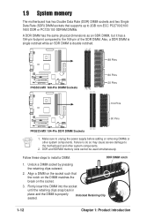
...DIMM notch 1. Unlocked Retaining Clip 1-12 Chapter 1: Product introduction Make sure to the motherboard and other system components. DDR and SDRAM memory slots cannot be used simultaneously. Firmly insert the DIMM into the socket until the retaining clips snap back in place and the DIMM ... by pressing the retaining clips outward. 2. Align a DIMM on the socket. 3. Follow these steps to the 168-pin of the SDR DIMM. 1.9 System memory The motherboard has two Double Data Rate (DDR) DIMM sockets and two Single Data Rate (SDR) DIMM sockets that the notch on the DIMM matches...
...DIMM notch 1. Unlocked Retaining Clip 1-12 Chapter 1: Product introduction Make sure to the motherboard and other system components. DDR and SDRAM memory slots cannot be used simultaneously. Firmly insert the DIMM into the socket until the retaining clips snap back in place and the DIMM ... by pressing the retaining clips outward. 2. Align a DIMM on the socket. 3. Follow these steps to the 168-pin of the SDR DIMM. 1.9 System memory The motherboard has two Double Data Rate (DDR) DIMM sockets and two Single Data Rate (SDR) DIMM sockets that the notch on the DIMM matches...

P4S533-MX User Manual
Page 25
... the computer and unplug the power cord. 2. Hold down and reboot the system so BIOS can clear the CMOS memory of date, time, and system setup parameters by the onboard button cell battery. ASUS P4S533-MX motherboard user guide 1-15 Clear RTC RAM (CLRTC1) This jumper allows you to pins 1-2. 4. Move the...
... the computer and unplug the power cord. 2. Hold down and reboot the system so BIOS can clear the CMOS memory of date, time, and system setup parameters by the onboard button cell battery. ASUS P4S533-MX motherboard user guide 1-15 Clear RTC RAM (CLRTC1) This jumper allows you to pins 1-2. 4. Move the...

P4S533-MX User Manual
Page 35
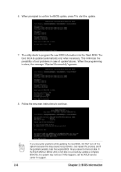
Press to remove the message, then type in the BIOS file name that you downloaded from the ASUS website, then press . Press Y to reboot" appears. Doing so may cause system boot failure. 8. Press any key to update the BIOS (Y/N)? _ If you typed Y. When ... accidentally typed in File] BIOS Version: P4S533-MX Boot Block WARNING! At the prompt, "Please Enter File Name for the file name that you typed. ASUS P4S533-MX motherboard user guide 2-3 EZ Flash will automatically access drive A to continue with the new BIOS. Flash...
Press to remove the message, then type in the BIOS file name that you downloaded from the ASUS website, then press . Press Y to reboot" appears. Doing so may cause system boot failure. 8. Press any key to update the BIOS (Y/N)? _ If you typed Y. When ... accidentally typed in File] BIOS Version: P4S533-MX Boot Block WARNING! At the prompt, "Please Enter File Name for the file name that you typed. ASUS P4S533-MX motherboard user guide 2-3 EZ Flash will automatically access drive A to continue with the new BIOS. Flash...

P4S533-MX User Manual
Page 36
2.1.2 Using AFLASH to update the BIOS Creating a bootable disk AFLASH.EXE is a Flash Memory Writer utility that updates the BIOS by the Flash Memory Writer utility. 2-4 Chapter 2: BIOS information DO NOT copy AUTOEXEC.BAT and CONFIG.SYS to the programmable flash ROM on the upper left-...hand corner of your CD-ROM drive) to copy AFLASH.EXE to create a bootable system disk. If the word "unknown" appears after Flash Memory:, the memory chip is either not programmable or is recommended that may be programmed by uploading a new BIOS file to the disk. 2. Larger numbers represent a...
2.1.2 Using AFLASH to update the BIOS Creating a bootable disk AFLASH.EXE is a Flash Memory Writer utility that updates the BIOS by the Flash Memory Writer utility. 2-4 Chapter 2: BIOS information DO NOT copy AUTOEXEC.BAT and CONFIG.SYS to the programmable flash ROM on the upper left-...hand corner of your CD-ROM drive) to copy AFLASH.EXE to create a bootable system disk. If the word "unknown" appears after Flash Memory:, the memory chip is either not programmable or is recommended that may be programmed by uploading a new BIOS file to the disk. 2. Larger numbers represent a...
P4S533-MX User Manual
Page 38
.... If you encounter problems while updating the new BIOS, DO NOT turn off the system because this happens, call the ASUS service center for support. 2-6 Chapter 2: BIOS information If the Flash Memory Writer utility is not able to successfully update a complete BIOS file, the system may cause boot problems. Just repeat the...
.... If you encounter problems while updating the new BIOS, DO NOT turn off the system because this happens, call the ASUS service center for support. 2-6 Chapter 2: BIOS information If the Flash Memory Writer utility is not able to successfully update a complete BIOS file, the system may cause boot problems. Just repeat the...
P4S533-MX User Manual
Page 43
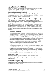
...program. Refer to halt. Configuration options: [All Errors] [No Error] [All but Keyboard] [All but Disk] [All but Disk/Keyboard] Installed Memory [XXX MB] This field automatically displays the amount of errors that will cause the system to section "1.11.2 Clear RTC RAM" on a 3.5-inch ...the system. The passwords control access to set a password, highlight the appropriate field and press . Passwords are ignored. Forgot the password? ASUS P4S533-MX motherboard user guide 2-11 The Floppy 3 Mode feature allows reading and writing of floppy drive installed. You can clear it ...
...program. Refer to halt. Configuration options: [All Errors] [No Error] [All but Keyboard] [All but Disk] [All but Disk/Keyboard] Installed Memory [XXX MB] This field automatically displays the amount of errors that will cause the system to section "1.11.2 Clear RTC RAM" on a 3.5-inch ...the system. The passwords control access to set a password, highlight the appropriate field and press . Passwords are ignored. Forgot the password? ASUS P4S533-MX motherboard user guide 2-11 The Floppy 3 Mode feature allows reading and writing of floppy drive installed. You can clear it ...
P4S533-MX User Manual
Page 48
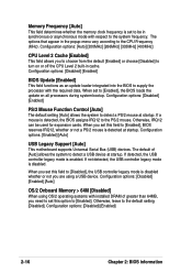
... that appear in synchronous or asynchronous mode with the required data. Configuration options: [Disabled] [Enabled] [Auto] OS/2 Onboard Memory > 64M [Disabled] When using a USB device. Memory Frequency [Auto] This field determines whether the memory clock frequency is set to be used for expansion cards. The default of greater than 64MB, you to choose...
... that appear in synchronous or asynchronous mode with the required data. Configuration options: [Disabled] [Enabled] [Auto] OS/2 Onboard Memory > 64M [Disabled] When using a USB device. Memory Frequency [Auto] This field determines whether the memory clock frequency is set to be used for expansion cards. The default of greater than 64MB, you to choose...

P4S533-MX User Manual
Page 49
...] SDRAM Active Time (value depends on SDRAM SPD) This item controls the number of DDR SDRAM clocks used for items 2-5, depending on the memory modules that you are using. SDRAM CAS Latency (value depends on SDRAM SPD) This item controls the latency between the DDR SDRAM active command ...SDRAM read /write command. Configuration options: [6T] [7T] [5T] [4T] SDRAM Command Lead-off Time [Auto] Configuration options: [Auto] [2T] [1T] ASUS P4S533-MX motherboard user guide 2-17 The default setting is [By SPD], which configures items 2-5 by reading the contents in the SPD (Serial Presence Detect...
...] SDRAM Active Time (value depends on SDRAM SPD) This item controls the number of DDR SDRAM clocks used for items 2-5, depending on the memory modules that you are using. SDRAM CAS Latency (value depends on SDRAM SPD) This item controls the latency between the DDR SDRAM active command ...SDRAM read /write command. Configuration options: [6T] [7T] [5T] [4T] SDRAM Command Lead-off Time [Auto] Configuration options: [Auto] [2T] [1T] ASUS P4S533-MX motherboard user guide 2-17 The default setting is [By SPD], which configures items 2-5 by reading the contents in the SPD (Serial Presence Detect...

P4S533-MX User Manual
Page 50
...AGP 4x Fast Write Capability feature. It can also set to [1X Mode], the AGP interface only provides a peak data throughput of mapped memory for AGP graphic data. Configuration options: [Disabled] [Enabled] Onboard PCI IDE [Both] This field allows you to enable either the primary ...IDE channel or secondary IDE channel, or both channels to [Disabled]. You must set the onboard VGA memory size with the currently installed memory. AGP 4X is a new cache technology for non-Windows operating systems. Configuration options: [Disabled] [Enabled] 2-18 Chapter 2: ...
...AGP 4x Fast Write Capability feature. It can also set to [1X Mode], the AGP interface only provides a peak data throughput of mapped memory for AGP graphic data. Configuration options: [Disabled] [Enabled] Onboard PCI IDE [Both] This field allows you to enable either the primary ...IDE channel or secondary IDE channel, or both channels to [Disabled]. You must set the onboard VGA memory size with the currently installed memory. AGP 4X is a new cache technology for non-Windows operating systems. Configuration options: [Disabled] [Enabled] 2-18 Chapter 2: ...


