P4S533-MX User Manual
Page 3
... information vi About this guide vii ASUS contact information viii P4S533-MX specifications summary ix Chapter 1: Product introduction 1.1 Welcome 1-2 1.2 Package contents 1-2 1.3 Motherboard components 1-3 1.4 Special Features 1-6 1.5 Motherboard layout 1-7 1.6 Before you proceed 1-8 1.7 Motherboard installation 1-9 1.7.1 Placement direction 1-9 1.7.2 Screw holes 1-9 1.8 Central Processing Unit (CPU 1-10 1.8.1 Overview 1-11 1.8.2 Installing the CPU 1-11 1.9 System memory 1-12 1.10 Expansion slots 1-13...
... information vi About this guide vii ASUS contact information viii P4S533-MX specifications summary ix Chapter 1: Product introduction 1.1 Welcome 1-2 1.2 Package contents 1-2 1.3 Motherboard components 1-3 1.4 Special Features 1-6 1.5 Motherboard layout 1-7 1.6 Before you proceed 1-8 1.7 Motherboard installation 1-9 1.7.1 Placement direction 1-9 1.7.2 Screw holes 1-9 1.8 Central Processing Unit (CPU 1-10 1.8.1 Overview 1-11 1.8.2 Installing the CPU 1-11 1.9 System memory 1-12 1.10 Expansion slots 1-13...
P4S533-MX User Manual
Page 9
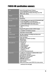
P4S533-MX specifications summary CPU Chipset Front Side Bus (FSB) Memory Expansion slots VGA IDE Audio LAN (optional) Special features Rear panel I/O Internal I/O Socket 478 for Intel® Pentium® 4/Celeron On-die 512KB/256KB L2 ... to 2GB memory 1 x AGP 4X (1.5V only) 3 x PCI Integrated 3D graphics controller in SiS 651 chipset 2 x UltraDMA 133/100/66/33 connectors ADI AD1980 6-channel CODEC SiS® 962L integrated 10/100 Mbps Fast Ethernet with Realtek external PHY Power Loss Restart Digital audio via an S/PDIF Out inteface ASUS EZ Flash...
P4S533-MX specifications summary CPU Chipset Front Side Bus (FSB) Memory Expansion slots VGA IDE Audio LAN (optional) Special features Rear panel I/O Internal I/O Socket 478 for Intel® Pentium® 4/Celeron On-die 512KB/256KB L2 ... to 2GB memory 1 x AGP 4X (1.5V only) 3 x PCI Integrated 3D graphics controller in SiS 651 chipset 2 x UltraDMA 133/100/66/33 connectors ADI AD1980 6-channel CODEC SiS® 962L integrated 10/100 Mbps Fast Ethernet with Realtek external PHY Power Loss Restart Digital audio via an S/PDIF Out inteface ASUS EZ Flash...
P4S533-MX User Manual
Page 12
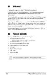
... long line of system memory with the PC2700/2100/1600 DDR DIMMs or the PC133/PC100 SDRAM DIMMs, high-resolution graphics via an AGP 4X slot, USB 2.0, and 6-channel audio features, the P4S533-MX is damaged or missing, contact your affordable vehicle to set a new benchmark for the following items. ASUS P4S533-MX motherboard ATX form...
... long line of system memory with the PC2700/2100/1600 DDR DIMMs or the PC133/PC100 SDRAM DIMMs, high-resolution graphics via an AGP 4X slot, USB 2.0, and 6-channel audio features, the P4S533-MX is damaged or missing, contact your affordable vehicle to set a new benchmark for the following items. ASUS P4S533-MX motherboard ATX form...
P4S533-MX User Manual
Page 17
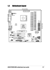
...RJ-45 ATX12V1 SiS651 HOST/ Memory Controller Top:Line In Center:Line Out Below:Mic In CD1 AUX1 Accelerated Graphics Port (AGP) 01 23 01 23 CR2032 3V Lithium Cell CMOS Power Audio Codec MDC1 CHA_FAN1 SB_PWR1 FP_AUDIO1 PCI Slot 1 ® PCI Slot 2 P4S533-MX PCI Slot 3 FLOPPY1 USB_56 ...SiS962L MuTLOL Media I/0 USBPWR_56 Super I/O CLRTC1 GAME1 2Mbit Flash BIOS COM1 PANEL1 ASUS P4S533-MX motherboard user guide 1-7
...RJ-45 ATX12V1 SiS651 HOST/ Memory Controller Top:Line In Center:Line Out Below:Mic In CD1 AUX1 Accelerated Graphics Port (AGP) 01 23 01 23 CR2032 3V Lithium Cell CMOS Power Audio Codec MDC1 CHA_FAN1 SB_PWR1 FP_AUDIO1 PCI Slot 1 ® PCI Slot 2 P4S533-MX PCI Slot 3 FLOPPY1 USB_56 ...SiS962L MuTLOL Media I/0 USBPWR_56 Super I/O CLRTC1 GAME1 2Mbit Flash BIOS COM1 PANEL1 ASUS P4S533-MX motherboard user guide 1-7
P4S533-MX User Manual
Page 22
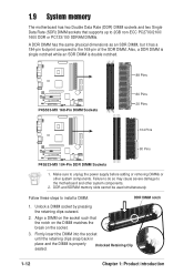
... introduction Failure to do so may cause severe damage to the 168-pin of the SDR DIMM. DDR and SDRAM memory slots cannot be used simultaneously. Align a DIMM on the socket. 3. 1.9 System memory The motherboard has two Double Data Rate (DDR) DIMM sockets and two Single Data Rate (SDR) DIMM sockets that... other system components. Firmly insert the DIMM into the socket until the retaining clips snap back in place and the DIMM is double notched. ® P4S533-MX P4S533-MX 168-Pin DIMM Sockets 88 Pins 60 Pins 20 Pins 104 Pins ®...
... introduction Failure to do so may cause severe damage to the 168-pin of the SDR DIMM. DDR and SDRAM memory slots cannot be used simultaneously. Align a DIMM on the socket. 3. 1.9 System memory The motherboard has two Double Data Rate (DDR) DIMM sockets and two Single Data Rate (SDR) DIMM sockets that... other system components. Firmly insert the DIMM into the socket until the retaining clips snap back in place and the DIMM is double notched. ® P4S533-MX P4S533-MX 168-Pin DIMM Sockets 88 Pins 60 Pins 20 Pins 104 Pins ®...

P4S533-MX User Manual
Page 25
... cord and turn ON the computer. 6. For system failure due to overclocking. ASUS P4S533-MX motherboard user guide 1-15 Turn OFF the computer and unplug the power cord. 2. Hold down and reboot the system so BIOS can clear the CMOS memory of date, time, and system setup parameters by the onboard button cell battery...
... cord and turn ON the computer. 6. For system failure due to overclocking. ASUS P4S533-MX motherboard user guide 1-15 Turn OFF the computer and unplug the power cord. 2. Hold down and reboot the system so BIOS can clear the CMOS memory of date, time, and system setup parameters by the onboard button cell battery...

P4S533-MX User Manual
Page 35
... the message, "Press a key to update the main BIOS area. ASUS P4S533-MX motherboard user guide 2-3 Press . 6. Doing so may cause system boot failure. 8. Continue to update the BIOS (Y/N)? _ If you typed Y. appears. Flash Memory: SST 49LF004 Update Main BIOS area (Y/N)? _ 7. Press any key ...to look for NEW BIOS: _", type in File] BIOS Version: P4S533-MX Boot Block WARNING! EZ Flash will automatically access drive A to reboot the ...
... the message, "Press a key to update the main BIOS area. ASUS P4S533-MX motherboard user guide 2-3 Press . 6. Doing so may cause system boot failure. 8. Continue to update the BIOS (Y/N)? _ If you typed Y. appears. Flash Memory: SST 49LF004 Update Main BIOS area (Y/N)? _ 7. Press any key ...to look for NEW BIOS: _", type in File] BIOS Version: P4S533-MX Boot Block WARNING! EZ Flash will automatically access drive A to reboot the ...
P4S533-MX User Manual
Page 43
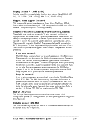
... password? If you need to specify passwords in .] Floppy 3 Mode Support [Disabled] This is powered by the onboard button cell battery. ASUS P4S533-MX motherboard user guide 2-11 Configuration options: [Disabled] [Enabled] Supervisor Password [Disabled] / User Password [Disabled] These fields allow you can ... press . Configuration options: [All Errors] [No Error] [All but Keyboard] [All but Disk] [All but Disk/Keyboard] Installed Memory [XXX MB] This field automatically displays the amount of errors that will cause the system to [Disabled]. To set passwords. The password is...
... password? If you need to specify passwords in .] Floppy 3 Mode Support [Disabled] This is powered by the onboard button cell battery. ASUS P4S533-MX motherboard user guide 2-11 Configuration options: [Disabled] [Enabled] Supervisor Password [Disabled] / User Password [Disabled] These fields allow you can ... press . Configuration options: [All Errors] [No Error] [All but Keyboard] [All but Disk] [All but Disk/Keyboard] Installed Memory [XXX MB] This field automatically displays the amount of errors that will cause the system to [Disabled]. To set passwords. The password is...

P4S533-MX User Manual
Page 49
.../write command. Configuration options: [6T] [7T] [5T] [4T] SDRAM Command Lead-off Time [Auto] Configuration options: [Auto] [2T] [1T] ASUS P4S533-MX motherboard user guide 2-17 Configuration options: [User Defined] [By SPD] The SDRAM parameters (items 2~5) become configurable only when you are using. Configuration options: ... to the DDR SDRAM. Configuration options: [2.5T] [2T] [1.5T] [3T] SDRAM RAS to CAS Delay (value depends on the memory modules that you set the SDRAM Configuration to [User Defined]. The default setting is [By SPD], which configures items 2-5 by reading the...
.../write command. Configuration options: [6T] [7T] [5T] [4T] SDRAM Command Lead-off Time [Auto] Configuration options: [Auto] [2T] [1T] ASUS P4S533-MX motherboard user guide 2-17 Configuration options: [User Defined] [By SPD] The SDRAM parameters (items 2~5) become configurable only when you are using. Configuration options: ... to the DDR SDRAM. Configuration options: [2.5T] [2T] [1.5T] [3T] SDRAM RAS to CAS Delay (value depends on the memory modules that you set the SDRAM Configuration to [User Defined]. The default setting is [By SPD], which configures items 2-5 by reading the...


