
Motherboard DIY Troubleshooting Guide
Page 1
P4S533-MX Motherboard
P4S533-MX Motherboard

P4S533-MX User Manual
Page 1
Motherboard P4S533-MX User Guide
Motherboard P4S533-MX User Guide
P4S533-MX User Manual
Page 3
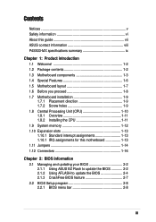
Features Contents Notices v Safety information vi About this guide vii ASUS contact information viii P4S533-MX specifications summary ix Chapter 1: Product introduction 1.1 Welcome 1-2 1.2 Package contents 1-2 1.3 Motherboard components 1-3 1.4 Special Features 1-6 1.5 Motherboard layout 1-7 1.6 Before you proceed 1-8 1.7 Motherboard installation 1-9 1.7.1 Placement direction 1-9 1.7.2 Screw holes 1-9 1.8 Central Processing Unit (CPU 1-10 1.8.1 Overview 1-11 1.8.2 Installing the CPU 1-11 1.9 System memory 1-12 1.10 Expansion...
Features Contents Notices v Safety information vi About this guide vii ASUS contact information viii P4S533-MX specifications summary ix Chapter 1: Product introduction 1.1 Welcome 1-2 1.2 Package contents 1-2 1.3 Motherboard components 1-3 1.4 Special Features 1-6 1.5 Motherboard layout 1-7 1.6 Before you proceed 1-8 1.7 Motherboard installation 1-9 1.7.1 Placement direction 1-9 1.7.2 Screw holes 1-9 1.8 Central Processing Unit (CPU 1-10 1.8.1 Overview 1-11 1.8.2 Installing the CPU 1-11 1.9 System memory 1-12 1.10 Expansion...

P4S533-MX User Manual
Page 11
It includes brief descriptions of the motherboard components, and illustrations of the P4S533-MX motherboard. Product introduction Chapter 1 This chapter describes the features of the layout, jumper settings, and connectors.
It includes brief descriptions of the motherboard components, and illustrations of the P4S533-MX motherboard. Product introduction Chapter 1 This chapter describes the features of the layout, jumper settings, and connectors.
P4S533-MX User Manual
Page 12
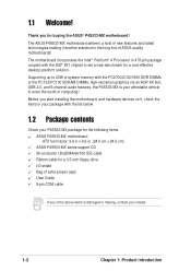
...and latest technologies making it , check the items in your package with the list below. 1.2 Package contents Check your P4S533-MX package for the following items. ASUS P4S533-MX motherboard ATX form factor: 9.6 in x 9.6 in 478-pin package coupled with the PC2700/2100/1600 DDR DIMMs or the... memory with the SiS® 651 chipset to set a new benchmark for buying the ASUS® P4S533-MX motherboard! The motherboard incorporates the Intel® Pentium® 4 Processor in (24.5 cm x 24.5 cm) ASUS P4S533-MX series support CD 80-conductor UltraDMA/66/100 IDE cable Ribbon cable for a 3.5-...
...and latest technologies making it , check the items in your package with the list below. 1.2 Package contents Check your P4S533-MX package for the following items. ASUS P4S533-MX motherboard ATX form factor: 9.6 in x 9.6 in 478-pin package coupled with the PC2700/2100/1600 DDR DIMMs or the... memory with the SiS® 651 chipset to set a new benchmark for buying the ASUS® P4S533-MX motherboard! The motherboard incorporates the Intel® Pentium® 4 Processor in (24.5 cm x 24.5 cm) ASUS P4S533-MX series support CD 80-conductor UltraDMA/66/100 IDE cable Ribbon cable for a 3.5-...
P4S533-MX User Manual
Page 13
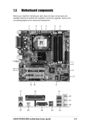
Refer to facilitate the installation and future upgrades. 1.3 Motherboard components Before you install the motherboard, learn about its major components and available features to the succeeding pages for the component descriptions. 1 2 34 56 16 15 14 13 12 17 18 11 19 27 26 25 24 23 ASUS P4S533-MX motherboard user guide 7 8 9 10 20 21 22 1-3
Refer to facilitate the installation and future upgrades. 1.3 Motherboard components Before you install the motherboard, learn about its major components and available features to the succeeding pages for the component descriptions. 1 2 34 56 16 15 14 13 12 17 18 11 19 27 26 25 24 23 ASUS P4S533-MX motherboard user guide 7 8 9 10 20 21 22 1-3
P4S533-MX User Manual
Page 15
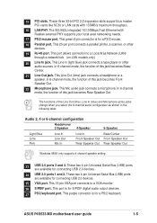
... connecting USB 2.0 devices. 24 USB 2.0 ports 1 and 2. These two 4-pin Universal Serial Bus (USB) ports are available for connecting USB 2.0 devices. 25 VGA port. ASUS P4S533-MX motherboard user guide 1-5 This Line In (light blue) jack connects a tape player or other devices. 19 RJ-45 port. This Mic (pink) jack connects a microphone. 15...
... connecting USB 2.0 devices. 24 USB 2.0 ports 1 and 2. These two 4-pin Universal Serial Bus (USB) ports are available for connecting USB 2.0 devices. 25 VGA port. ASUS P4S533-MX motherboard user guide 1-5 This Line In (light blue) jack connects a tape player or other devices. 19 RJ-45 port. This Mic (pink) jack connects a microphone. 15...
P4S533-MX User Manual
Page 16
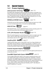
... automatically restore the CPU default setting for up to 3.0+ GHz core frequencies for each parameter. Unlike other competing vendors' products, ASUS motherboards now enable users to enjoy this protection feature without the need to open the case to 4.2GB/s data transfer rates. 1.4 ...Special Features 1.4.1 Product highlights Latest processor technology (page 1-10) The P4S533-MX motherboard supports the latest Intel® Pentium® 4 Processor via a 478-pin surface mount ZIF socket. The Pentium 4 processor with Yamaha ...
... automatically restore the CPU default setting for up to 3.0+ GHz core frequencies for each parameter. Unlike other competing vendors' products, ASUS motherboards now enable users to enjoy this protection feature without the need to open the case to 4.2GB/s data transfer rates. 1.4 ...Special Features 1.4.1 Product highlights Latest processor technology (page 1-10) The P4S533-MX motherboard supports the latest Intel® Pentium® 4 Processor via a 478-pin surface mount ZIF socket. The Pentium 4 processor with Yamaha ...
P4S533-MX User Manual
Page 17
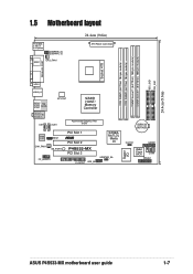
...DIMM Socket 1 (64/72-bit, 168-pin module) DIMM Socket 1 (64/72-bit, 168-pin module) SEC_IDE1 PRI_IDE1 24.4cm (9.6in) 1.5 Motherboard layout PS/2KBMS T: Mouse B: Keyboard USBPWR_34 USBPWR_12 SPDIF1 CPU_FAN1 24.4cm (9.6in) ATX Power Connector PARALLEL PORT VGA1 USB20_12 Bottom: USB3 USB4 Top: ...23 01 23 CR2032 3V Lithium Cell CMOS Power Audio Codec MDC1 CHA_FAN1 SB_PWR1 FP_AUDIO1 PCI Slot 1 ® PCI Slot 2 P4S533-MX PCI Slot 3 FLOPPY1 USB_56 SiS962L MuTLOL Media I/0 USBPWR_56 Super I/O CLRTC1 GAME1 2Mbit Flash BIOS COM1 PANEL1 ASUS P4S533-MX motherboard user guide 1-7
...DIMM Socket 1 (64/72-bit, 168-pin module) DIMM Socket 1 (64/72-bit, 168-pin module) SEC_IDE1 PRI_IDE1 24.4cm (9.6in) 1.5 Motherboard layout PS/2KBMS T: Mouse B: Keyboard USBPWR_34 USBPWR_12 SPDIF1 CPU_FAN1 24.4cm (9.6in) ATX Power Connector PARALLEL PORT VGA1 USB20_12 Bottom: USB3 USB4 Top: ...23 01 23 CR2032 3V Lithium Cell CMOS Power Audio Codec MDC1 CHA_FAN1 SB_PWR1 FP_AUDIO1 PCI Slot 1 ® PCI Slot 2 P4S533-MX PCI Slot 3 FLOPPY1 USB_56 SiS962L MuTLOL Media I/0 USBPWR_56 Super I/O CLRTC1 GAME1 2Mbit Flash BIOS COM1 PANEL1 ASUS P4S533-MX motherboard user guide 1-7
P4S533-MX User Manual
Page 18
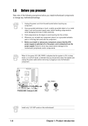
... to static electricity. 3. Before you install or remove any component, ensure that you uninstall any motherboard component. ® P4S533-MX P4S533-MX Onboard LED SB_PWR1 ON Standby Power OFF Powered Off Install only 1.5V AGP cards on this motherboard! 1-8 Chapter 1: Product introduction When lit, the green LED (SB_PWR1) indicates that the system is ON...
... to static electricity. 3. Before you install or remove any component, ensure that you uninstall any motherboard component. ® P4S533-MX P4S533-MX Onboard LED SB_PWR1 ON Standby Power OFF Powered Off Install only 1.5V AGP cards on this motherboard! 1-8 Chapter 1: Product introduction When lit, the green LED (SB_PWR1) indicates that the system is ON...
P4S533-MX User Manual
Page 19
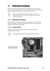
...towards the rear of your chassis to ensure that the motherboard fits into the holes indicated by circles to secure the motherboard to do so may damage the motherboard. Do not overtighten the screws! Failure to the ...motherboard. Doing so may cause you physical injury and damage motherboard components. 1.7.1 Placement direction When installing the motherboard, make sure that measures 9.6 inches x 9.6 inches (24.5 cm x 24.5 cm). The motherboard uses the micro-ATX form factor that you install the motherboard, study the configuration of the chassis ASUS P4S533-MX motherboard...
...towards the rear of your chassis to ensure that the motherboard fits into the holes indicated by circles to secure the motherboard to do so may damage the motherboard. Do not overtighten the screws! Failure to the ...motherboard. Doing so may cause you physical injury and damage motherboard components. 1.7.1 Placement direction When installing the motherboard, make sure that measures 9.6 inches x 9.6 inches (24.5 cm x 24.5 cm). The motherboard uses the micro-ATX form factor that you install the motherboard, study the configuration of the chassis ASUS P4S533-MX motherboard...
P4S533-MX User Manual
Page 21
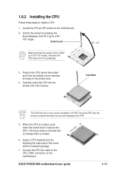
... lifted up to prevent bending the pins and damaging the CPU! 5. Carefully insert the CPU into the socket to a 90°- 100° angle. ASUS P4S533-MX motherboard user guide 1-11 Socket Lever Make sure that its marked corner matches the base of the socket lever. 4. When the CPU is locked. 6. Gold Mark... The CPU fits only in place. The lever clicks on the side tab to secure the CPU. Locate the 478-pin ZIF socket on the motherboard. 2. Unlock the socket by pressing the lever sideways, then lift it up to 90°-100° angle, otherwise the CPU does not fit in...
... lifted up to prevent bending the pins and damaging the CPU! 5. Carefully insert the CPU into the socket to a 90°- 100° angle. ASUS P4S533-MX motherboard user guide 1-11 Socket Lever Make sure that its marked corner matches the base of the socket lever. 4. When the CPU is locked. 6. Gold Mark... The CPU fits only in place. The lever clicks on the side tab to secure the CPU. Locate the 478-pin ZIF socket on the motherboard. 2. Unlock the socket by pressing the lever sideways, then lift it up to 90°-100° angle, otherwise the CPU does not fit in...
P4S533-MX User Manual
Page 22
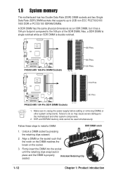
... until the retaining clips snap back in place and the DIMM is double notched. ® P4S533-MX P4S533-MX 168-Pin DIMM Sockets 88 Pins 60 Pins 20 Pins 104 Pins ® P4S533-MX 80 Pins P4S533-MX 184-Pin DDR DIMM Sockets 1. Align a DIMM on the socket such that supports up... DDR DIMM has the same physical dimensions as an SDR DIMM, but it has a 184-pin footprint compared to install a DIMM. Make sure to the motherboard and other system components. Unlock a DIMM socket by pressing the retaining clips outward. 2. Failure to do so may cause severe damage to unplug the power...
... until the retaining clips snap back in place and the DIMM is double notched. ® P4S533-MX P4S533-MX 168-Pin DIMM Sockets 88 Pins 60 Pins 20 Pins 104 Pins ® P4S533-MX 80 Pins P4S533-MX 184-Pin DDR DIMM Sockets 1. Align a DIMM on the socket such that supports up... DDR DIMM has the same physical dimensions as an SDR DIMM, but it has a 184-pin footprint compared to install a DIMM. Make sure to the motherboard and other system components. Unlock a DIMM socket by pressing the retaining clips outward. 2. Failure to do so may cause severe damage to unplug the power...
P4S533-MX User Manual
Page 23
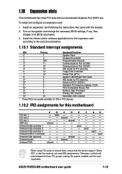
See Chapter 2 for this motherboard A B C D E PCI slot 1 - shared - - shared - ASUS P4S533-MX motherboard user guide 1-13 Install an expansion card following the instructions that the cards do not need IRQ assignments. shared ... PCI slot 3 - - - Onboard USB controller 1 - - - - Onboard USB 2.0 controller - - - - - Onboard VGA shared - - - - GH used -- -- -- 1.10 Expansion slots The motherboard has three PCI slots and one Accelerated Graphics Port (AGP) slot. When using PCI cards on the system and change the necessary BIOS settings, if...
See Chapter 2 for this motherboard A B C D E PCI slot 1 - shared - - shared - ASUS P4S533-MX motherboard user guide 1-13 Install an expansion card following the instructions that the cards do not need IRQ assignments. shared ... PCI slot 3 - - - Onboard USB controller 1 - - - - Onboard USB 2.0 controller - - - - - Onboard VGA shared - - - - GH used -- -- -- 1.10 Expansion slots The motherboard has three PCI slots and one Accelerated Graphics Port (AGP) slot. When using PCI cards on the system and change the necessary BIOS settings, if...

P4S533-MX User Manual
Page 25
Plug the power cord and turn ON the computer. 6. 2. For system failure due to pins 2-3. ASUS P4S533-MX motherboard user guide 1-15 You can automatically reset parameter settings to default values. Move the jumper cap from pins 1-2 (default) to overclocking, use the C.P.R. (CPU Parameter ...
Plug the power cord and turn ON the computer. 6. 2. For system failure due to pins 2-3. ASUS P4S533-MX motherboard user guide 1-15 You can automatically reset parameter settings to default values. Move the jumper cap from pins 1-2 (default) to overclocking, use the C.P.R. (CPU Parameter ...
P4S533-MX User Manual
Page 26
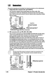
... hole on the floppy ribbon cable to PIN 1 SEC_IDE1 PRI_IDE1 1-16 ® P4S533-MX P4S533-MX IDE Connectors PIN 1 PIN 1 Chapter 1: Product introduction BIOS supports specific device bootup. Pin 20 on the motherboard. 1. After connecting one for the primary IDE connector and another UltraDMA133/100/66 ... connect the cables. You may configure two hard disks to the hard disk documentation for the secondary IDE connector. one end to the motherboard, connect the other end to the floppy drive. (Pin 5 is removed to the secondary IDE connector. Refer to be both master ...
... hole on the floppy ribbon cable to PIN 1 SEC_IDE1 PRI_IDE1 1-16 ® P4S533-MX P4S533-MX IDE Connectors PIN 1 PIN 1 Chapter 1: Product introduction BIOS supports specific device bootup. Pin 20 on the motherboard. 1. After connecting one for the primary IDE connector and another UltraDMA133/100/66 ... connect the cables. You may configure two hard disks to the hard disk documentation for the secondary IDE connector. one end to the motherboard, connect the other end to the floppy drive. (Pin 5 is removed to the secondary IDE connector. Refer to be both master ...
P4S533-MX User Manual
Page 27
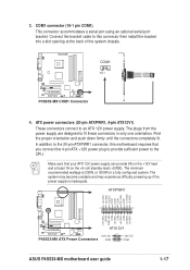
... COM -12.0VDC +3.3VDC +12.0VDC +5VSB PWR_OK COM +5.0VDC COM +5.0VDC COM +3.3VDC +3.3VDC ® P4S533-MX ATX12V1 +12V DC P4S533-MX ATX Power Connectors COM +12V DC COM ASUS P4S533-MX motherboard user guide 1-17 ATX power connectors (20-pin ATXPWR1, 4-pin ATX12V1) These connectors connect to fit these connectors in... powering up if the power supply is 230W, or 300W for a fully configured system. In addition to the 20-pin ATXPWR1 connector, this motherboard requires that your ATX 12V power supply can provide 8A on the +12V lead and at the back of the system chassis. COM1 connector (...
... COM -12.0VDC +3.3VDC +12.0VDC +5VSB PWR_OK COM +5.0VDC COM +5.0VDC COM +3.3VDC +3.3VDC ® P4S533-MX ATX12V1 +12V DC P4S533-MX ATX Power Connectors COM +12V DC COM ASUS P4S533-MX motherboard user guide 1-17 ATX power connectors (20-pin ATXPWR1, 4-pin ATX12V1) These connectors connect to fit these connectors in... powering up if the power supply is 230W, or 300W for a fully configured system. In addition to the 20-pin ATXPWR1 connector, this motherboard requires that your ATX 12V power supply can provide 8A on the +12V lead and at the back of the system chassis. COM1 connector (...

P4S533-MX User Manual
Page 28
...cooling fans of 350mA~740mA (8.88W max.) or a total of sufficient air flow within the system may damage the motherboard components. CPU_FAN1 GND +12V Rotation ® P4S533-MX GND +12V Rotation CHA_FAN1 P4S533-MX 12-Volt Cooling Fan Power 6. The USB/GAME module is purchased separately. +5V J1B2 J1CY GND GND ... fan connectors on the fan connectors! Do not forget to connect the fan cables to this connector. DO NOT place jumper caps on the motherboard, making sure that the black wire of each cable matches the ground pin of the connector. The GAME/MIDI port on the module connects ...
...cooling fans of 350mA~740mA (8.88W max.) or a total of sufficient air flow within the system may damage the motherboard components. CPU_FAN1 GND +12V Rotation ® P4S533-MX GND +12V Rotation CHA_FAN1 P4S533-MX 12-Volt Cooling Fan Power 6. The USB/GAME module is purchased separately. +5V J1B2 J1CY GND GND ... fan connectors on the fan connectors! Do not forget to connect the fan cables to this connector. DO NOT place jumper caps on the motherboard, making sure that the black wire of each cable matches the ground pin of the connector. The GAME/MIDI port on the module connects ...

P4S533-MX User Manual
Page 29
The module has two USB 2.0 ports that supports up to this header. AGND +5VA BLINE_OUT_R BLINE_OUT_L ® P4S533-MX FP_AUDIO1 P4S533-MX Front Panel Audio Connector ASUS P4S533-MX motherboard user guide MIC2 MICPWR Line out_R NC Line out_L 1-19 7. You may connect an optional USB 2.0/GAME module... the Intel front panel audio cable that allow convenient connection and control of high-speed peripherals. USB+6V USB_P6USB_P6+ GND NC ® P4S533-MX P4S533-MX USB 2.0 Header USB56 (Blue) 1 USB+5V USB_P5USB_P5+ GND 8. Front panel audio connector (10-1 pin FP_AUDIO1) This is ...
The module has two USB 2.0 ports that supports up to this header. AGND +5VA BLINE_OUT_R BLINE_OUT_L ® P4S533-MX FP_AUDIO1 P4S533-MX Front Panel Audio Connector ASUS P4S533-MX motherboard user guide MIC2 MICPWR Line out_R NC Line out_L 1-19 7. You may connect an optional USB 2.0/GAME module... the Intel front panel audio cable that allow convenient connection and control of high-speed peripherals. USB+6V USB_P6USB_P6+ GND NC ® P4S533-MX P4S533-MX USB 2.0 Header USB56 (Blue) 1 USB+5V USB_P5USB_P5+ GND 8. Front panel audio connector (10-1 pin FP_AUDIO1) This is ...
P4S533-MX User Manual
Page 31
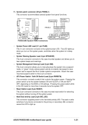
Power LED Speaker Connector +5VSB PLED +5V Ground Ground Speaker PANEL1 IDELED+ IDELED- ASUS P4S533-MX motherboard user guide 1-21 P4S533-MX System Panel Connectors • System Power LED Lead (3-1 pin PLED) This 3-1 pin connector connects to this LED to light up when you...-Off Switch Lead (2-pin PWRBTN) This connector connects a switch that controls the system power. 11. Ground ExtSMI# Ground PWR Ground Reset Ground ® P4S533-MX IDE_LED SMI Lead Reset SW ATX Power Switch* * Requires an ATX power supply. The LED lights up . The read or write activities of certain...
Power LED Speaker Connector +5VSB PLED +5V Ground Ground Speaker PANEL1 IDELED+ IDELED- ASUS P4S533-MX motherboard user guide 1-21 P4S533-MX System Panel Connectors • System Power LED Lead (3-1 pin PLED) This 3-1 pin connector connects to this LED to light up when you...-Off Switch Lead (2-pin PWRBTN) This connector connects a switch that controls the system power. 11. Ground ExtSMI# Ground PWR Ground Reset Ground ® P4S533-MX IDE_LED SMI Lead Reset SW ATX Power Switch* * Requires an ATX power supply. The LED lights up . The read or write activities of certain...


