
Motherboard DIY Troubleshooting Guide
Page 5
Motherboard-Layout PS/2KBMS T: Mouse B: Keyboard USBPW34 USBPW12 CPU_FAN1 ATX Power Connector USBPW34 USBPW12 12 23 +5V (Default) +5VSB SPDIF_OUT ...Graphics Port (AGP) Audio Codec CHA_FAN1 FP_AUDIO1 CD1 AUX1 PCI Slot 1 PCI Slot 2 SB_PWR1 PCI Slot 3 PCI Slot 4 ® PCI Slot 5 P4S-X PCI Slot 6 USB56 01 23 CR2032 3V Lithium Cell CMOS Power SiS962L MuTLOL Media I/0 CLRTC1 GAME1 2Mbit Flash BIOS COM2 Super I/O FLOPPY1 BUZZER1 USBPW56...478 DDR DIMM1 (64/72 bit, 184-pin module) DDR DIMM2 (64/72 bit, 184-pin module) SEC_IDE1 PRI_IDE1 Deutsch 1. ASUS P4S-X-Motherboard 5
Motherboard-Layout PS/2KBMS T: Mouse B: Keyboard USBPW34 USBPW12 CPU_FAN1 ATX Power Connector USBPW34 USBPW12 12 23 +5V (Default) +5VSB SPDIF_OUT ...Graphics Port (AGP) Audio Codec CHA_FAN1 FP_AUDIO1 CD1 AUX1 PCI Slot 1 PCI Slot 2 SB_PWR1 PCI Slot 3 PCI Slot 4 ® PCI Slot 5 P4S-X PCI Slot 6 USB56 01 23 CR2032 3V Lithium Cell CMOS Power SiS962L MuTLOL Media I/0 CLRTC1 GAME1 2Mbit Flash BIOS COM2 Super I/O FLOPPY1 BUZZER1 USBPW56...478 DDR DIMM1 (64/72 bit, 184-pin module) DDR DIMM2 (64/72 bit, 184-pin module) SEC_IDE1 PRI_IDE1 Deutsch 1. ASUS P4S-X-Motherboard 5

P4S-X User Manual
Page 1
Motherboard P4S-X User Guide
Motherboard P4S-X User Guide
P4S-X User Manual
Page 3
Features Contents Notices v Safety information vi About this guide vii ASUS contact information viii P4S-X specifications summary ix Chapter 1: Product introduction 1.1 Welcome 1-2 1.2 Package contents 1-2 1.3 Motherboard components 1-3 1.4 Special Features 1-6 1.5 Motherboard layout 1-7 1.6 Before you proceed 1-8 1.7 Motherboard installation 1-9 1.7.1 Placement direction 1-9 1.7.2 Screw holes 1-9 1.8 Central Processing Unit (CPU 1-10 1.8.1 Overview 1-11 1.8.2 Installing the CPU 1-11 1.9 System memory 1-12 1.10 Expansion slots...
Features Contents Notices v Safety information vi About this guide vii ASUS contact information viii P4S-X specifications summary ix Chapter 1: Product introduction 1.1 Welcome 1-2 1.2 Package contents 1-2 1.3 Motherboard components 1-3 1.4 Special Features 1-6 1.5 Motherboard layout 1-7 1.6 Before you proceed 1-8 1.7 Motherboard installation 1-9 1.7.1 Placement direction 1-9 1.7.2 Screw holes 1-9 1.8 Central Processing Unit (CPU 1-10 1.8.1 Overview 1-11 1.8.2 Installing the CPU 1-11 1.9 System memory 1-12 1.10 Expansion slots...
P4S-X User Manual
Page 6
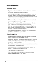
... service technician or your dealer immediately. • To avoid short circuits, keep paper clips, screws, and staples away from the motherboard, ensure that all the manuals that the power cables for the devices are unplugged before using the product, make sure all cables ...system before you encounter technical problems with the package. • Before using an adpater or extension cord. Operation safety • Before installing the motherboard and adding devices on a stable surface. • If you add a device. • Before connecting or removing signal cables from connectors, ...
... service technician or your dealer immediately. • To avoid short circuits, keep paper clips, screws, and staples away from the motherboard, ensure that all the manuals that the power cables for the devices are unplugged before using the product, make sure all cables ...system before you encounter technical problems with the package. • Before using an adpater or extension cord. Operation safety • Before installing the motherboard and adding devices on a stable surface. • If you add a device. • Before connecting or removing signal cables from connectors, ...

P4S-X User Manual
Page 11
Chapter 1 This chapter describes the features of the layout, jumper settings, and connectors. Product introduction It includes brief descriptions of the motherboard components, and illustrations of the P4S-X motherboard.
Chapter 1 This chapter describes the features of the layout, jumper settings, and connectors. Product introduction It includes brief descriptions of the motherboard components, and illustrations of the P4S-X motherboard.
P4S-X User Manual
Page 12
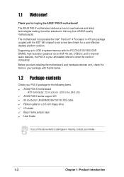
...® Pentium® 4 Processor in 478-pin package coupled with the list below. 1.2 Package contents Check your P4S-X package for the following items. ASUS P4S-X motherboard ATX form factor: 12 in x 9.6 in (30.5 cm x 24.5 cm) ASUS P4S-X series support CD 80-conductor UltraDMA33/66/100/133 IDE cable Ribbon cable for a 3.5-inch floppy drive I/O shield...
...® Pentium® 4 Processor in 478-pin package coupled with the list below. 1.2 Package contents Check your P4S-X package for the following items. ASUS P4S-X motherboard ATX form factor: 12 in x 9.6 in (30.5 cm x 24.5 cm) ASUS P4S-X series support CD 80-conductor UltraDMA33/66/100/133 IDE cable Ribbon cable for a 3.5-inch floppy drive I/O shield...

P4S-X User Manual
Page 13
1.3 Motherboard components Before you install the motherboard, learn about its major components and available features to the succeeding pages for the component descriptions. 1 2 34 5 6 16 15 14 13 7 12 8 17 18 11 10 9 19 27 26 25 24 23 ASUS P4S-X motherboard user guide 20 21 22 1-3 Refer to facilitate the installation and future upgrades.
1.3 Motherboard components Before you install the motherboard, learn about its major components and available features to the succeeding pages for the component descriptions. 1 2 34 5 6 16 15 14 13 7 12 8 17 18 11 10 9 19 27 26 25 24 23 ASUS P4S-X motherboard user guide 20 21 22 1-3 Refer to facilitate the installation and future upgrades.

P4S-X User Manual
Page 14
... commonly used Super I /O controller. This 20-pin connector connects to a COM2 port. 8 Floppy disk connector. The power supply must have at least 1A on the motherboard. One side of the floppy disk cable. 9 Flash ROM. This Accelerated Graphics Port (AGP) slot supports 1.5V AGP4X mode graphics cards for a 360K/720K/1.44M...
... commonly used Super I /O controller. This 20-pin connector connects to a COM2 port. 8 Floppy disk connector. The power supply must have at least 1A on the motherboard. One side of the floppy disk cable. 9 Flash ROM. This Accelerated Graphics Port (AGP) slot supports 1.5V AGP4X mode graphics cards for a 360K/720K/1.44M...
P4S-X User Manual
Page 15
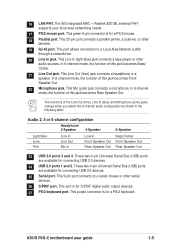
... Speaker Out Rear Speaker Out 23 USB 2.0 ports 3 and 4. This 9-pin port connects to a Local Area Network (LAN) through a network hub. 20 Line In jack. ASUS P4S-X motherboard user guide 1-5 This green 6-pin connector is for S/PDIF digital audio output devices. 27 PS/2 keyboard port. This Line Out (lime) jack connects a headphone or...
... Speaker Out Rear Speaker Out 23 USB 2.0 ports 3 and 4. This 9-pin port connects to a Local Area Network (LAN) through a network hub. 20 Line In jack. ASUS P4S-X motherboard user guide 1-5 This green 6-pin connector is for S/PDIF digital audio output devices. 27 PS/2 keyboard port. This Line Out (lime) jack connects a headphone or...

P4S-X User Manual
Page 16
... for each parameter. SoundMAX Digital Audio System can update BIOS before entering operating system. 1.4 Special Features 1.4.1 Product highlights ASUS EZ Flash (page 2-2) With ASUS EZ Flash, you can output 5.1 channel surround and features state-of-the-art DLS2 MIDI synthesizer with Yamaha DLSbyXG sound... Parameter Recall) (page 1-15) When the system hangs due to pay for an optional ROM. Unlike other competing vendors' products, ASUS motherboards now enable users to enjoy this protection feature without the need to open the case to restore BIOS data from a floppy diskette even...
... for each parameter. SoundMAX Digital Audio System can update BIOS before entering operating system. 1.4 Special Features 1.4.1 Product highlights ASUS EZ Flash (page 2-2) With ASUS EZ Flash, you can output 5.1 channel surround and features state-of-the-art DLS2 MIDI synthesizer with Yamaha DLSbyXG sound... Parameter Recall) (page 1-15) When the system hangs due to pay for an optional ROM. Unlike other competing vendors' products, ASUS motherboards now enable users to enjoy this protection feature without the need to open the case to restore BIOS data from a floppy diskette even...
P4S-X User Manual
Page 17
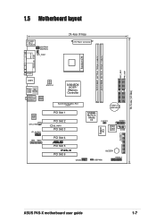
SEC_IDE1 PRI_IDE1 1.5 Motherboard layout PS/2KBMS T: Mouse B: Keyboard USBPW34 USBPW12 CPU_FAN1 24.4cm (9.6in) ATX Power Connector Socket 478 DDR DIMM1 (64/72 bit, 184-pin module) DDR ... (AGP) Audio Codec CHA_FAN1 FP_AUDIO1 CD1 AUX1 PCI Slot 1 PCI Slot 2 SB_PWR1 PCI Slot 3 PCI Slot 4 ® PCI Slot 5 P4S-X PCI Slot 6 USB56 01 23 CR2032 3V Lithium Cell CMOS Power SiS962L MuTLOL Media I/0 CLRTC1 GAME1 2Mbit Flash BIOS COM2 Super I/O FLOPPY1 BUZZER1 USBPW56 PANEL1 30.5cm (12.0in) ASUS P4S-X motherboard user guide 1-7
SEC_IDE1 PRI_IDE1 1.5 Motherboard layout PS/2KBMS T: Mouse B: Keyboard USBPW34 USBPW12 CPU_FAN1 24.4cm (9.6in) ATX Power Connector Socket 478 DDR DIMM1 (64/72 bit, 184-pin module) DDR ... (AGP) Audio Codec CHA_FAN1 FP_AUDIO1 CD1 AUX1 PCI Slot 1 PCI Slot 2 SB_PWR1 PCI Slot 3 PCI Slot 4 ® PCI Slot 5 P4S-X PCI Slot 6 USB56 01 23 CR2032 3V Lithium Cell CMOS Power SiS962L MuTLOL Media I/0 CLRTC1 GAME1 2Mbit Flash BIOS COM2 Super I/O FLOPPY1 BUZZER1 USBPW56 PANEL1 30.5cm (12.0in) ASUS P4S-X motherboard user guide 1-7

P4S-X User Manual
Page 18
1.6 Before you proceed Take note of the following precautions before you install motherboard components or change any motherboard component. Unplug the power cord from the power supply. Whenever you uninstall any component. 2. Before you should shut ...metal object, such as the power supply case, before touching any component, place it on this motherboard! 1-8 Chapter 1: Product introduction Hold components by the edges to static electricity. 3. SB_PWR1 ® P4S-X P4S-X Onboard LED ON Standby Power OFF Powered Off Install only 1.5V AGP cards on a grounded antistatic...
1.6 Before you proceed Take note of the following precautions before you install motherboard components or change any motherboard component. Unplug the power cord from the power supply. Whenever you uninstall any component. 2. Before you should shut ...metal object, such as the power supply case, before touching any component, place it on this motherboard! 1-8 Chapter 1: Product introduction Hold components by the edges to static electricity. 3. SB_PWR1 ® P4S-X P4S-X Onboard LED ON Standby Power OFF Powered Off Install only 1.5V AGP cards on a grounded antistatic...

P4S-X User Manual
Page 19
... . Doing so may cause you physical injury and damage motherboard components. 1.7.1 Placement direction When installing the motherboard, make sure that measures 12 inches x 9.6 inches (30.5 cm x 24.5 cm). Place this side towards the rear of the chassis ASUS P4S-X motherboard user guide 1-9 1.7 Motherboard installation Before you install the motherboard, study the configuration of your chassis to ensure...
... . Doing so may cause you physical injury and damage motherboard components. 1.7.1 Placement direction When installing the motherboard, make sure that measures 12 inches x 9.6 inches (30.5 cm x 24.5 cm). Place this side towards the rear of the chassis ASUS P4S-X motherboard user guide 1-9 1.7 Motherboard installation Before you install the motherboard, study the configuration of your chassis to ensure...

P4S-X User Manual
Page 20
... for the Intel® Pentium® 4 Processor in the illustration that should match a specific corner of the CPU socket. 1.8 Central Processing Unit (CPU) 1.8.1 Overview The motherboard comes with 512/256KB L2 cache on one corner.
... for the Intel® Pentium® 4 Processor in the illustration that should match a specific corner of the CPU socket. 1.8 Central Processing Unit (CPU) 1.8.1 Overview The motherboard comes with 512/256KB L2 cache on one corner.

P4S-X User Manual
Page 21
...tab to indicate that the socket lever is locked. 6. The lever clicks on the motherboard. Unlock the socket by pressing the lever sideways, then lift it fits in completely. 90 - 100 3. ASUS P4S-X motherboard user guide 1-11 Socket Lever Make sure that it is lifted up to secure the ...CPU. Gold Mark The CPU fits only in place, push down the socket lever to a 90°- 100° angle. Locate the 478-pin ZIF socket on the motherboard. 2. Carefully ...
...tab to indicate that the socket lever is locked. 6. The lever clicks on the motherboard. Unlock the socket by pressing the lever sideways, then lift it fits in completely. 90 - 100 3. ASUS P4S-X motherboard user guide 1-11 Socket Lever Make sure that it is lifted up to secure the ...CPU. Gold Mark The CPU fits only in place, push down the socket lever to a 90°- 100° angle. Locate the 478-pin ZIF socket on the motherboard. 2. Carefully ...

P4S-X User Manual
Page 22
... the power supply before adding or removing DIMMs or other system components. 2. Unlocked Retaining Clip 1-12 Chapter 1: Product introduction 1.9 System memory The motherboard has two Double Data Rate (DDR) DIMM sockets that the notch on the DIMM matches the break on the socket. 3. Follow these steps to... Firmly insert the DIMM into the socket until the retaining clips snap back in place and the DIMM is double notched. 104 Pins ® P4S-X P4S-X 184-Pin DDR DIMM Sockets 80 Pins 1. Align a DIMM on the socket such that supports up to 2GB non-ECC PC2700/2100/1600 DDR...
... the power supply before adding or removing DIMMs or other system components. 2. Unlocked Retaining Clip 1-12 Chapter 1: Product introduction 1.9 System memory The motherboard has two Double Data Rate (DDR) DIMM sockets that the notch on the DIMM matches the break on the socket. 3. Follow these steps to... Firmly insert the DIMM into the socket until the retaining clips snap back in place and the DIMM is double notched. 104 Pins ® P4S-X P4S-X 184-Pin DDR DIMM Sockets 80 Pins 1. Align a DIMM on the socket such that supports up to 2GB non-ECC PC2700/2100/1600 DDR...
P4S-X User Manual
Page 23
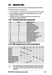
...1.10 Expansion slots The motherboard has six PCI slots and one Accelerated Graphics Port (AGP) slot. See Chapter 2 for this motherboard A B C D E... PCI slot 1 - PCI slot 2 - - Onboard USB 2.0 controller - - - - - To install and configure an expansion card: 1. PCI slot 4 shared - - - - PCI slot 5 - shared - - - Onboard USB controller 1 - - - - Onboard LAN (optional) - - - F used Onboard USB controller 2 - - - - - When using PCI cards on the system and change the necessary BIOS settings, if any. ASUS P4S-X motherboard...
...1.10 Expansion slots The motherboard has six PCI slots and one Accelerated Graphics Port (AGP) slot. See Chapter 2 for this motherboard A B C D E... PCI slot 1 - PCI slot 2 - - Onboard USB 2.0 controller - - - - - To install and configure an expansion card: 1. PCI slot 4 shared - - - - PCI slot 5 - shared - - - Onboard USB controller 1 - - - - Onboard LAN (optional) - - - F used Onboard USB controller 2 - - - - - When using PCI cards on the system and change the necessary BIOS settings, if any. ASUS P4S-X motherboard...
P4S-X User Manual
Page 25
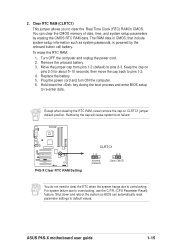
... cap on pins 2-3 for about 5~10 seconds, then move the cap back to re-enter data. Removing the cap will cause system boot failure! ® P4S-X P4S-X Clear RTC RAM Setting CLRTC1 12 Normal (Default) 23 Clear CMOS You do not need to clear the RTC when the system hangs due to... computer. 6. Clear RTC RAM (CLRTC1) This jumper allows you to overclocking, use the C.P.R. (CPU Parameter Recall) feature. Keep the cap on CLRTC1 jumper default position. ASUS P4S-X motherboard user guide 1-15 The RAM data in CMOS. 2. Remove the onboard battery. 3.
... cap on pins 2-3 for about 5~10 seconds, then move the cap back to re-enter data. Removing the cap will cause system boot failure! ® P4S-X P4S-X Clear RTC RAM Setting CLRTC1 12 Normal (Default) 23 Clear CMOS You do not need to clear the RTC when the system hangs due to... computer. 6. Clear RTC RAM (CLRTC1) This jumper allows you to overclocking, use the C.P.R. (CPU Parameter Recall) feature. Keep the cap on CLRTC1 jumper default position. ASUS P4S-X motherboard user guide 1-15 The RAM data in CMOS. 2. Remove the onboard battery. 3.
P4S-X User Manual
Page 26
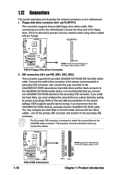
...incorrect insertion when using ribbon cables with two ribbon cables - one end to the motherboard, connect the other end to the floppy drive. (Pin 5 is removed to match the covered hole on the motherboard. 1. If you connect non-UltraDMA133/100/66 devices to the hard disk documentation ...ribbon cable to be both master devices with pin 5 plug). If you install two hard disks, you connect the cables. 1-16 ® P4S-X P4S-X IDE Connectors SEC_IDE1 PRI_IDE1 NOTE: Orient the red markings on the floppy ribbon cable to the UltraDMA133/100/66 master device. Connect the cable...
...incorrect insertion when using ribbon cables with two ribbon cables - one end to the motherboard, connect the other end to the floppy drive. (Pin 5 is removed to match the covered hole on the motherboard. 1. If you connect non-UltraDMA133/100/66 devices to the hard disk documentation ...ribbon cable to be both master devices with pin 5 plug). If you install two hard disks, you connect the cables. 1-16 ® P4S-X P4S-X IDE Connectors SEC_IDE1 PRI_IDE1 NOTE: Orient the red markings on the floppy ribbon cable to the UltraDMA133/100/66 master device. Connect the cable...
P4S-X User Manual
Page 27
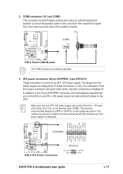
...minimum recommended wattage is inadequate. +5.0VDC +5.0VDC -5.0VDC COM COM COM PS_ON# COM -12.0VDC +3.3VDC ATXPWR1 ® P4S-X P4S-X ATX Power Connectors ATX12V1 +12V DC COM +12V DC COM ASUS P4S-X motherboard user guide +12.0VDC +5VSB PWR_OK COM +5.0VDC COM +5.0VDC COM +3.3VDC +3.3VDC 1-17 3. The system may become ...the back of the system chassis. Make sure that you connect the 4-pin ATX +12V power plug to provide sufficient power to this motherboard requires that your ATX 12V power supply can provide 8A on the +5-volt standby lead (+5VSB). The plugs from the power supply are...
...minimum recommended wattage is inadequate. +5.0VDC +5.0VDC -5.0VDC COM COM COM PS_ON# COM -12.0VDC +3.3VDC ATXPWR1 ® P4S-X P4S-X ATX Power Connectors ATX12V1 +12V DC COM +12V DC COM ASUS P4S-X motherboard user guide +12.0VDC +5VSB PWR_OK COM +5.0VDC COM +5.0VDC COM +3.3VDC +3.3VDC 1-17 3. The system may become ...the back of the system chassis. Make sure that you connect the 4-pin ATX +12V power plug to provide sufficient power to this motherboard requires that your ATX 12V power supply can provide 8A on the +5-volt standby lead (+5VSB). The plugs from the power supply are...


