
Motherboard DIY Troubleshooting Guide
Page 2
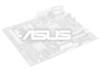
... CHA_FAN1 FP_AUDIO1 CD1 AUX1 PCI Slot 1 PCI Slot 2 SB_PWR1 PCI Slot 3 PCI Slot 4 ® PCI Slot 5 P4S-X PCI Slot 6 USB56 01 23 CR2032 3V Lithium Cell CMOS Power SiS962L MuTLOL Media I/0 CLRTC1 GAME1 2Mbit Flash BIOS COM2 Super I/O FLOPPY1 BUZZER1 USBPW56 PANEL1 CLRTC1 12 23 Normal (Default) Clear CMOS PANEL1 USBPW56 12... +5V IDELED ExtSMI# Ground PWR Ground Reset Ground IDE_LED SMI Lead Bouton de reset Commutateur d'alimentation ATX* * Nécessite une alimentation ATX. 2 Carte mère ASUS P4S-X Français 1.
... CHA_FAN1 FP_AUDIO1 CD1 AUX1 PCI Slot 1 PCI Slot 2 SB_PWR1 PCI Slot 3 PCI Slot 4 ® PCI Slot 5 P4S-X PCI Slot 6 USB56 01 23 CR2032 3V Lithium Cell CMOS Power SiS962L MuTLOL Media I/0 CLRTC1 GAME1 2Mbit Flash BIOS COM2 Super I/O FLOPPY1 BUZZER1 USBPW56 PANEL1 CLRTC1 12 23 Normal (Default) Clear CMOS PANEL1 USBPW56 12... +5V IDELED ExtSMI# Ground PWR Ground Reset Ground IDE_LED SMI Lead Bouton de reset Commutateur d'alimentation ATX* * Nécessite une alimentation ATX. 2 Carte mère ASUS P4S-X Français 1.

Motherboard DIY Troubleshooting Guide
Page 5
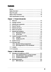
ASUS P4S-X-Motherboard 5 Motherboard-Layout PS/2KBMS T: Mouse B: Keyboard USBPW34 USBPW12 CPU_FAN1 ATX Power Connector USBPW34 USBPW12 12 23 +5V (Default) +5VSB SPDIF_OUT PARALLEL PORT COM1 USB12 ... CHA_FAN1 FP_AUDIO1 CD1 AUX1 PCI Slot 1 PCI Slot 2 SB_PWR1 PCI Slot 3 PCI Slot 4 ® PCI Slot 5 P4S-X PCI Slot 6 USB56 01 23 CR2032 3V Lithium Cell CMOS Power SiS962L MuTLOL Media I/0 CLRTC1 GAME1 2Mbit Flash BIOS COM2 Super I/O FLOPPY1 BUZZER1 USBPW56 PANEL1 CLRTC1 12 23 Normal (Default) Clear CMOS PANEL1 USBPW56 12...
ASUS P4S-X-Motherboard 5 Motherboard-Layout PS/2KBMS T: Mouse B: Keyboard USBPW34 USBPW12 CPU_FAN1 ATX Power Connector USBPW34 USBPW12 12 23 +5V (Default) +5VSB SPDIF_OUT PARALLEL PORT COM1 USB12 ... CHA_FAN1 FP_AUDIO1 CD1 AUX1 PCI Slot 1 PCI Slot 2 SB_PWR1 PCI Slot 3 PCI Slot 4 ® PCI Slot 5 P4S-X PCI Slot 6 USB56 01 23 CR2032 3V Lithium Cell CMOS Power SiS962L MuTLOL Media I/0 CLRTC1 GAME1 2Mbit Flash BIOS COM2 Super I/O FLOPPY1 BUZZER1 USBPW56 PANEL1 CLRTC1 12 23 Normal (Default) Clear CMOS PANEL1 USBPW56 12...

Motherboard DIY Troubleshooting Guide
Page 11
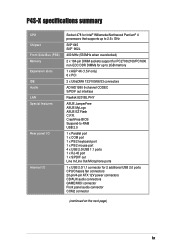
Español Placa base ASUS P4S-X 11 1. Distribución de placa base PS/2KBMS T: Mouse B: Keyboard USBPW34 USBPW12 CPU_FAN1 ATX Power Connector USBPW34 USBPW12 12 23 +5V (Default) +5VSB Socket 478 ... CHA_FAN1 FP_AUDIO1 CD1 AUX1 PCI Slot 1 PCI Slot 2 SB_PWR1 PCI Slot 3 PCI Slot 4 ® PCI Slot 5 P4S-X PCI Slot 6 USB56 01 23 CR2032 3V Lithium Cell CMOS Power SiS962L MuTLOL Media I/0 CLRTC1 GAME1 2Mbit Flash BIOS COM2 Super I/O FLOPPY1 BUZZER1 USBPW56 PANEL1 CLRTC1 12 23 Normal (Default) Clear CMOS PANEL1 USBPW56 12...
Español Placa base ASUS P4S-X 11 1. Distribución de placa base PS/2KBMS T: Mouse B: Keyboard USBPW34 USBPW12 CPU_FAN1 ATX Power Connector USBPW34 USBPW12 12 23 +5V (Default) +5VSB Socket 478 ... CHA_FAN1 FP_AUDIO1 CD1 AUX1 PCI Slot 1 PCI Slot 2 SB_PWR1 PCI Slot 3 PCI Slot 4 ® PCI Slot 5 P4S-X PCI Slot 6 USB56 01 23 CR2032 3V Lithium Cell CMOS Power SiS962L MuTLOL Media I/0 CLRTC1 GAME1 2Mbit Flash BIOS COM2 Super I/O FLOPPY1 BUZZER1 USBPW56 PANEL1 CLRTC1 12 23 Normal (Default) Clear CMOS PANEL1 USBPW56 12...

Motherboard DIY Troubleshooting Guide
Page 14
... 2 SB_PWR1 PCI Slot 3 PCI Slot 4 ® PCI Slot 5 P4S-X PCI Slot 6 USB56 01 23 CR2032 3V Lithium Cell CMOS Power SiS962L MuTLOL Media I/0 CLRTC1 GAME1 2Mbit Flash BIOS COM2 Super I/O FLOPPY1 BUZZER1 USBPW56 PANEL1 CLRTC1 12 23 Normal (Default) ...Clear CMOS PANEL1 USBPW56 12 23 +5V (Default) +5VSB PLED+ PLED+5V Ground Ground Speaker +5V IDELED ExtSMI# Ground PWR Ground Reset Ground IDE_LED SMI ATX* ATX. усский 14 ASUS P4S...
... 2 SB_PWR1 PCI Slot 3 PCI Slot 4 ® PCI Slot 5 P4S-X PCI Slot 6 USB56 01 23 CR2032 3V Lithium Cell CMOS Power SiS962L MuTLOL Media I/0 CLRTC1 GAME1 2Mbit Flash BIOS COM2 Super I/O FLOPPY1 BUZZER1 USBPW56 PANEL1 CLRTC1 12 23 Normal (Default) ...Clear CMOS PANEL1 USBPW56 12 23 +5V (Default) +5VSB PLED+ PLED+5V Ground Ground Speaker +5V IDELED ExtSMI# Ground PWR Ground Reset Ground IDE_LED SMI ATX* ATX. усский 14 ASUS P4S...
P4S-X User Manual
Page 3
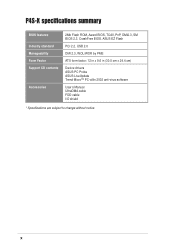
Features Contents Notices v Safety information vi About this guide vii ASUS contact information viii P4S-X specifications summary ix Chapter 1: Product introduction 1.1 Welcome 1-2 1.2 Package contents 1-2 1.3 Motherboard components 1-3 1.4 Special Features 1-6 1.5 Motherboard ...motherboard 1-13 1.11 Jumpers 1-14 1.12 Connectors 1-16 Chapter 2: BIOS information 2.1 Managing and updating your BIOS 2-2 2.1.1 Using ASUS EZ Flash to update the BIOS 2-2 2.1.2 Using AFLASH to update the BIOS 2-4 2.1.3 CrashFree BIOS feature 2-7 2.2 BIOS Setup program 2-8 2.2.1 BIOS menu bar 2-8 iii
Features Contents Notices v Safety information vi About this guide vii ASUS contact information viii P4S-X specifications summary ix Chapter 1: Product introduction 1.1 Welcome 1-2 1.2 Package contents 1-2 1.3 Motherboard components 1-3 1.4 Special Features 1-6 1.5 Motherboard ...motherboard 1-13 1.11 Jumpers 1-14 1.12 Connectors 1-16 Chapter 2: BIOS information 2.1 Managing and updating your BIOS 2-2 2.1.1 Using ASUS EZ Flash to update the BIOS 2-2 2.1.2 Using AFLASH to update the BIOS 2-4 2.1.3 CrashFree BIOS feature 2-7 2.2 BIOS Setup program 2-8 2.2.1 BIOS menu bar 2-8 iii
P4S-X User Manual
Page 9
P4S-X specifications summary CPU Chipset Front Side Bus (FSB) Memory Expansion slots IDE Audio LAN Special features Rear panel I/O Internal I/O Socket 478 for Intel® Willamette/.../4-pin ATX 12V power connectors CD/AUX audio connectors GAME/MIDI connector Front panel audio connector COM2 connector (continued on the next page) ix CrashFree BIOS Suspend-to 2GB memory 1 x AGP 4X (1.5V only) 6 x PCI 2 x UltraDMA 133/100/66/33 connectors ADI AD1980 6-channel CODEC S/PDIF out interface Realtek 8201BL PHY...
P4S-X specifications summary CPU Chipset Front Side Bus (FSB) Memory Expansion slots IDE Audio LAN Special features Rear panel I/O Internal I/O Socket 478 for Intel® Willamette/.../4-pin ATX 12V power connectors CD/AUX audio connectors GAME/MIDI connector Front panel audio connector COM2 connector (continued on the next page) ix CrashFree BIOS Suspend-to 2GB memory 1 x AGP 4X (1.5V only) 6 x PCI 2 x UltraDMA 133/100/66/33 connectors ADI AD1980 6-channel CODEC S/PDIF out interface Realtek 8201BL PHY...
P4S-X User Manual
Page 10
P4S-X specifications summary BIOS features Industry standard Manageability Form Factor Support CD contents Accessories 2Mb Flash ROM, Award BIOS, TCAV, PnP, DMI2.3, SM BIOS 2.3, CrashFree BIOS, ASUS EZ Flash PCI 2.2, USB 2.0 DMI 2.3, WOL/WOR by PME ATX form factor: 12 in x 9.6 in (30.5 cm x 24.4 cm) Device drivers ASUS PC Probe ASUS LiveUpdate Trend Micro™ PC-cillin 2002 anti-virus software User's Manual UltraDMA cable FDD cable I/O shield * Specifications are subject to change without notice. x
P4S-X specifications summary BIOS features Industry standard Manageability Form Factor Support CD contents Accessories 2Mb Flash ROM, Award BIOS, TCAV, PnP, DMI2.3, SM BIOS 2.3, CrashFree BIOS, ASUS EZ Flash PCI 2.2, USB 2.0 DMI 2.3, WOL/WOR by PME ATX form factor: 12 in x 9.6 in (30.5 cm x 24.4 cm) Device drivers ASUS PC Probe ASUS LiveUpdate Trend Micro™ PC-cillin 2002 anti-virus software User's Manual UltraDMA cable FDD cable I/O shield * Specifications are subject to change without notice. x

P4S-X User Manual
Page 14
This 2Mb firmware contains the programmable BIOS program. 10 Super I /O functionality. The ADI AD1980 is slotted to prevent incorrect insertion of the floppy disk cable. 9 Flash ROM. The audio CODEC provides six ...
This 2Mb firmware contains the programmable BIOS program. 10 Super I /O functionality. The ADI AD1980 is slotted to prevent incorrect insertion of the floppy disk cable. 9 Flash ROM. The audio CODEC provides six ...

P4S-X User Manual
Page 16
...business professionals, audiophiles, musicians, and gamers. 1.4 Special Features 1.4.1 Product highlights ASUS EZ Flash (page 2-2) With ASUS EZ Flash, you can output 5.1 channel surround and features state-of-the-...art DLS2 MIDI synthesizer with Yamaha DLSbyXG sound set, 5.1 Virtual Theater™ and supports all major game audio technologies including Microsoft DirectX™8.0, Microsoft DirectSound 3D™, A3D, MacroFX, ZoomFX, MultiDrive 5.1 and EAX. 1-6 Chapter 1: Product introduction CrashFree BIOS...
...business professionals, audiophiles, musicians, and gamers. 1.4 Special Features 1.4.1 Product highlights ASUS EZ Flash (page 2-2) With ASUS EZ Flash, you can output 5.1 channel surround and features state-of-the-...art DLS2 MIDI synthesizer with Yamaha DLSbyXG sound set, 5.1 Virtual Theater™ and supports all major game audio technologies including Microsoft DirectX™8.0, Microsoft DirectSound 3D™, A3D, MacroFX, ZoomFX, MultiDrive 5.1 and EAX. 1-6 Chapter 1: Product introduction CrashFree BIOS...
P4S-X User Manual
Page 17
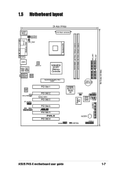
... (AGP) Audio Codec CHA_FAN1 FP_AUDIO1 CD1 AUX1 PCI Slot 1 PCI Slot 2 SB_PWR1 PCI Slot 3 PCI Slot 4 ® PCI Slot 5 P4S-X PCI Slot 6 USB56 01 23 CR2032 3V Lithium Cell CMOS Power SiS962L MuTLOL Media I/0 CLRTC1 GAME1 2Mbit Flash BIOS COM2 Super I/O FLOPPY1 BUZZER1 USBPW56 PANEL1 30.5cm (12.0in) ASUS P4S-X motherboard user guide 1-7
... (AGP) Audio Codec CHA_FAN1 FP_AUDIO1 CD1 AUX1 PCI Slot 1 PCI Slot 2 SB_PWR1 PCI Slot 3 PCI Slot 4 ® PCI Slot 5 P4S-X PCI Slot 6 USB56 01 23 CR2032 3V Lithium Cell CMOS Power SiS962L MuTLOL Media I/0 CLRTC1 GAME1 2Mbit Flash BIOS COM2 Super I/O FLOPPY1 BUZZER1 USBPW56 PANEL1 30.5cm (12.0in) ASUS P4S-X motherboard user guide 1-7
P4S-X User Manual
Page 23
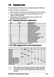
... Data Processor 14* 9 Primary IDE Channel 15* 10 Secondary IDE Channel * These IRQs are usually available for ISA or PCI devices. 1.10.2 IRQ assignments for BIOS information. 3. shared - - Onboard USB controller 1 - - - - Install an expansion card following the instructions that the cards do not need IRQ assignments. shared - - ... the card inoperable. AGP slot shared - - - - When using PCI cards on the system and change the necessary BIOS settings, if any. used - - Onboard audio - - ASUS P4S-X motherboard user guide 1-13 Onboard USB controller 3 - - - - -
... Data Processor 14* 9 Primary IDE Channel 15* 10 Secondary IDE Channel * These IRQs are usually available for ISA or PCI devices. 1.10.2 IRQ assignments for BIOS information. 3. shared - - Onboard USB controller 1 - - - - Install an expansion card following the instructions that the cards do not need IRQ assignments. shared - - ... the card inoperable. AGP slot shared - - - - When using PCI cards on the system and change the necessary BIOS settings, if any. used - - Onboard audio - - ASUS P4S-X motherboard user guide 1-13 Onboard USB controller 3 - - - - -
P4S-X User Manual
Page 25
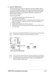
...the cap back to default values. Turn OFF the computer and unplug the power cord. 2. ASUS P4S-X motherboard user guide 1-15 Replace the battery. 5. Hold down and reboot the system so BIOS can clear the CMOS memory of date, time, and system setup parameters by the onboard button... (CPU Parameter Recall) feature. Shut down the key during the boot process and enter BIOS setup to overclocking. Remove the onboard battery. 3. Removing the cap will cause system boot failure! ® P4S-X P4S-X Clear RTC RAM Setting CLRTC1 12 Normal (Default) 23 Clear CMOS You do not need...
...the cap back to default values. Turn OFF the computer and unplug the power cord. 2. ASUS P4S-X motherboard user guide 1-15 Replace the battery. 5. Hold down and reboot the system so BIOS can clear the CMOS memory of date, time, and system setup parameters by the onboard button... (CPU Parameter Recall) feature. Shut down the key during the boot process and enter BIOS setup to overclocking. Remove the onboard battery. 3. Removing the cap will cause system boot failure! ® P4S-X P4S-X Clear RTC RAM Setting CLRTC1 12 Normal (Default) 23 Clear CMOS You do not need...
P4S-X User Manual
Page 26
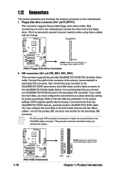
...floppy ribbon cable to the hard disk documentation for the jumper settings. It is recommended that you connect the cables. 1-16 ® P4S-X P4S-X IDE Connectors SEC_IDE1 PRI_IDE1 NOTE: Orient the red markings on each IDE connector is removed to be both master devices with pin 5 plug...). Refer to PIN 1. Floppy disk drive connector (34-1 pin FLOPPY1) This connector supports the provided floppy drive ribbon cable. BIOS supports specific device bootup. Pin 20 on the IDE ribbon cable to the secondary IDE connector. This prevents incorrect orientation when you connect non...
...floppy ribbon cable to the hard disk documentation for the jumper settings. It is recommended that you connect the cables. 1-16 ® P4S-X P4S-X IDE Connectors SEC_IDE1 PRI_IDE1 NOTE: Orient the red markings on each IDE connector is removed to be both master devices with pin 5 plug...). Refer to PIN 1. Floppy disk drive connector (34-1 pin FLOPPY1) This connector supports the provided floppy drive ribbon cable. BIOS supports specific device bootup. Pin 20 on the IDE ribbon cable to the secondary IDE connector. This prevents incorrect orientation when you connect non...
P4S-X User Manual
Page 31
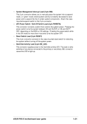
... write activities of certain system components. Pressing the power switch turns the system between ON and SLEEP, or ON and SOFT OFF, depending on the BIOS or OS settings. • System Management Interrupt Lead (2-pin SMI) This 2-pin connector allows you to manually place the system into a suspend mode, or "green... the system without turning off the system power. • Hard Disk Activity Lead (2-pin IDE_LED) This connector supplies power to this LED to light up. ASUS P4S-X motherboard user guide 1-21
... write activities of certain system components. Pressing the power switch turns the system between ON and SLEEP, or ON and SOFT OFF, depending on the BIOS or OS settings. • System Management Interrupt Lead (2-pin SMI) This 2-pin connector allows you to manually place the system into a suspend mode, or "green... the system without turning off the system power. • Hard Disk Activity Lead (2-pin IDE_LED) This connector supplies power to this LED to light up. ASUS P4S-X motherboard user guide 1-21

P4S-X User Manual
Page 33
Detailed descriptions of the BIOS parameters are also provided. BIOS information Chapter 2 This chapter tells how to change system settings through the BIOS Setup menus.
Detailed descriptions of the BIOS parameters are also provided. BIOS information Chapter 2 This chapter tells how to change system settings through the BIOS Setup menus.
P4S-X User Manual
Page 34
... 5 without having to type the exact BIOS file name at the EZ Flash screen. 2. ASUS EZ Flash V1.00 Copyright (C) 2003, ASUSTeK COMPUTER INC. [Onboard BIOS Information] BIOS Version : ASUS P4S-X ACPI BIOS Revision 1002 BIOS Model : P4S-X BIOS Built Date : 07/09/03 Please Enter File Name for reference only. What you see ASUS contact information on page viii). Insert...
... 5 without having to type the exact BIOS file name at the EZ Flash screen. 2. ASUS EZ Flash V1.00 Copyright (C) 2003, ASUSTeK COMPUTER INC. [Onboard BIOS Information] BIOS Version : ASUS P4S-X ACPI BIOS Revision 1002 BIOS Model : P4S-X BIOS Built Date : 07/09/03 Please Enter File Name for reference only. What you see ASUS contact information on page viii). Insert...
P4S-X User Manual
Page 35
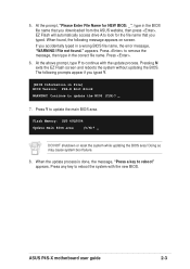
... to remove the message, then type in the correct file name. Press to look for NEW BIOS: _", type in the BIOS file name that you accidentally typed in File] BIOS Version: P4S-X Boot Block WARNING! Doing so may cause system boot failure. 8. appears. Press . 6. ...Flash screen and reboots the system without updating the BIOS. ASUS P4S-X motherboard user guide 2-3 The following message appears on screen. Flash Memory: SST 49LF004 Update Main BIOS area (Y/N)? _ DO NOT shutdown or reset the system while updating the BIOS area! 5. File not found , the following...
... to remove the message, then type in the correct file name. Press to look for NEW BIOS: _", type in the BIOS file name that you accidentally typed in File] BIOS Version: P4S-X Boot Block WARNING! Doing so may cause system boot failure. 8. appears. Press . 6. ...Flash screen and reboots the system without updating the BIOS. ASUS P4S-X motherboard user guide 2-3 The following message appears on screen. Flash Memory: SST 49LF004 Update Main BIOS area (Y/N)? _ DO NOT shutdown or reset the system while updating the BIOS area! 5. File not found , the following...
P4S-X User Manual
Page 36
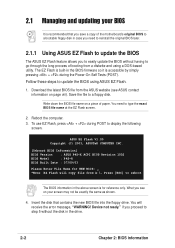
...disk. 3. Reboot the computer from the hard drive. 2.1.2 Using AFLASH to update the BIOS Creating a bootable disk AFLASH.EXE is a Flash Memory Writer utility that updates the BIOS by the Flash Memory Writer utility. 2-4 Chapter 2: BIOS information Type COPY D:\AFLASH\AFLASH.EXE A:\ (assuming D is your screen during bootup....that you created. In DOS mode, type A:\AFLASH to the disk. 2. DO NOT copy AUTOEXEC.BAT and CONFIG.SYS to run AFLASH. BIOS setup must specify "Floppy" as the first item in the DOS prompt within Windows, and does not work in the boot sequence. 4. ...
...disk. 3. Reboot the computer from the hard drive. 2.1.2 Using AFLASH to update the BIOS Creating a bootable disk AFLASH.EXE is a Flash Memory Writer utility that updates the BIOS by the Flash Memory Writer utility. 2-4 Chapter 2: BIOS information Type COPY D:\AFLASH\AFLASH.EXE A:\ (assuming D is your screen during bootup....that you created. In DOS mode, type A:\AFLASH to the disk. 2. DO NOT copy AUTOEXEC.BAT and CONFIG.SYS to run AFLASH. BIOS setup must specify "Floppy" as the first item in the DOS prompt within Windows, and does not work in the boot sequence. 4. ...
P4S-X User Manual
Page 37
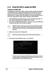
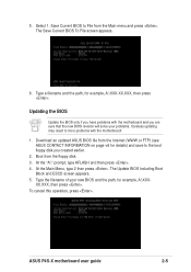
... path, for example, A:\XXX-XX.XXX, then press . 5. At the "A:\" prompt, type AFLASH and then press . 4. ASUS P4S-X motherboard user guide 2-5 XX.XXX, then press . Download an updated ASUS BIOS file from the Main menu and press . The Update BIOS Including Boot Block and ESCD screen appears. 5. To cancel this operation, press . Select 1. Updating the...
... path, for example, A:\XXX-XX.XXX, then press . 5. At the "A:\" prompt, type AFLASH and then press . 4. ASUS P4S-X motherboard user guide 2-5 XX.XXX, then press . Download an updated ASUS BIOS file from the Main menu and press . The Update BIOS Including Boot Block and ESCD screen appears. 5. To cancel this operation, press . Select 1. Updating the...
P4S-X User Manual
Page 38
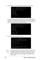
... the possibility of boot problems in case of update failures. If the Flash Memory Writer utility is not able to successfully update a complete BIOS file, the system may cause boot problems. Just repeat the process, and if the problem persists, load the original... BIOS file you encounter problems while updating the new BIOS, DO NOT turn off the system because this happens, call the ASUS service center for support. 2-6 Chapter 2: BIOS information The boot block is done, the message "Flashed Successfully" appears. 8....
... the possibility of boot problems in case of update failures. If the Flash Memory Writer utility is not able to successfully update a complete BIOS file, the system may cause boot problems. Just repeat the process, and if the problem persists, load the original... BIOS file you encounter problems while updating the new BIOS, DO NOT turn off the system because this happens, call the ASUS service center for support. 2-6 Chapter 2: BIOS information The boot block is done, the message "Flashed Successfully" appears. 8....


