P4PE-X/TE User Manual
Page 3
... guide vii Where to find more information vii ASUS contact information viii P4PE-X/TE specifications summary ix Chapter 1: Product introduction 1-1 ...1.1 Welcome 1-2 1.2 Package contents 1-2 1.3 Special features 1-2 1.4 Motherboard components 1-4 1.5 Motherboard layout 1-7 1.6 Before you proceed 1-8 1.7.1 Placement direction 1-9 1.7.2 Screw holes 1-9 1.7 Motherboard installation 1-9 1.8 Central Processing Unit (CPU 1-10 1.8.1 Overview 1-10 1.8.2 Installing the CPU 1-11 1.9 System memory 1-12 1.9.1 Memory...
... guide vii Where to find more information vii ASUS contact information viii P4PE-X/TE specifications summary ix Chapter 1: Product introduction 1-1 ...1.1 Welcome 1-2 1.2 Package contents 1-2 1.3 Special features 1-2 1.4 Motherboard components 1-4 1.5 Motherboard layout 1-7 1.6 Before you proceed 1-8 1.7.1 Placement direction 1-9 1.7.2 Screw holes 1-9 1.7 Motherboard installation 1-9 1.8 Central Processing Unit (CPU 1-10 1.8.1 Overview 1-10 1.8.2 Installing the CPU 1-11 1.9 System memory 1-12 1.9.1 Memory...

P4PE-X/TE User Manual
Page 9
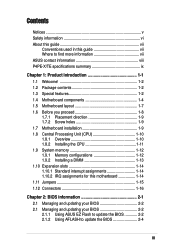
P4PE-X/TE specifications summary CPU Chipset Front Side Bus (FSB) Memory Expansion slots IDE Audio LAN Special features Rear panel I/O Internal I/O Socket 478 for Intel® Pentium® 4 / Celeron processors with speeds of up to 2GB memory Supports PC3200*/2700/2100...) 6 x PCI 2 x UltraDMA100/66/33 connectors ADI AD1888 6-channel audio CODEC Realtek® RTL8100C Fast Ethernet controller ASUS JumperFree™ mode ASUS EZ Flash ASUS CrashFree BIOS2 ASUS CPU Parameter Recall (C.P.R.) USB 2.0 ready Power Loss Restart SFS (Stepless Frequency Selection) CPU throttle Adjustable CPU Vcore 1 x...
P4PE-X/TE specifications summary CPU Chipset Front Side Bus (FSB) Memory Expansion slots IDE Audio LAN Special features Rear panel I/O Internal I/O Socket 478 for Intel® Pentium® 4 / Celeron processors with speeds of up to 2GB memory Supports PC3200*/2700/2100...) 6 x PCI 2 x UltraDMA100/66/33 connectors ADI AD1888 6-channel audio CODEC Realtek® RTL8100C Fast Ethernet controller ASUS JumperFree™ mode ASUS EZ Flash ASUS CrashFree BIOS2 ASUS CPU Parameter Recall (C.P.R.) USB 2.0 ready Power Loss Restart SFS (Stepless Frequency Selection) CPU throttle Adjustable CPU Vcore 1 x...

P4PE-X/TE User Manual
Page 12
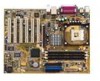
...mount ZIF socket. See page 1-10 for buying the ASUS® P4PE-X/TE motherboard! The ASUS P4PE-X/TE motherboard delivers a host of new features and latest technologies making it , check the items in the long line of system memory with PC3200*/2700/2100/1600 DDR SDRAM, high-resolution graphics... via an AGP 4X slot, USB 2.0, 10/100 Mbps LAN and 6-channel audio features, the P4PE-X/TE is damaged or missing, contact your P4PE-X/TE package for the following items. ASUS P4PE-X/TE motherboard ATX form factor...
...mount ZIF socket. See page 1-10 for buying the ASUS® P4PE-X/TE motherboard! The ASUS P4PE-X/TE motherboard delivers a host of new features and latest technologies making it , check the items in the long line of system memory with PC3200*/2700/2100/1600 DDR SDRAM, high-resolution graphics... via an AGP 4X slot, USB 2.0, 10/100 Mbps LAN and 6-channel audio features, the P4PE-X/TE is damaged or missing, contact your P4PE-X/TE package for the following items. ASUS P4PE-X/TE motherboard ATX form factor...
P4PE-X/TE User Manual
Page 13
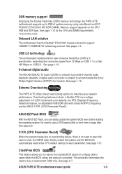
...2700/2100/1600 DDR DIMMs. Memory support depends on USB 2.0. See page 2-7. See page 1-16. 6-channel digital audio The ADI AD1888 AC '97 audio CODEC is present to buy a replacement ROM chip. Extreme Overclocking The P4PE-X/TE offers robust overclocking options to ...feature allows you can easily update the system BIOS even before loading the operating system. ASUS P4PE-X/TE motherboard user guide 1-3 DDR memory support Employing the Double Data Rate (DDR) memory technology, the P4PE-X/TE motherboard supports up to support 10BASE-T/100BASE-TX networking protocol. See page 1-12 for ...
...2700/2100/1600 DDR DIMMs. Memory support depends on USB 2.0. See page 2-7. See page 1-16. 6-channel digital audio The ADI AD1888 AC '97 audio CODEC is present to buy a replacement ROM chip. Extreme Overclocking The P4PE-X/TE offers robust overclocking options to ...feature allows you can easily update the system BIOS even before loading the operating system. ASUS P4PE-X/TE motherboard user guide 1-3 DDR memory support Employing the Double Data Rate (DDR) memory technology, the P4PE-X/TE motherboard supports up to support 10BASE-T/100BASE-TX networking protocol. See page 1-12 for ...
P4PE-X/TE User Manual
Page 15
..., SMBus 2.0 controller, LPC interface, AC'97 2.2 interface, and PCI 2.2 interface. ASUS P4PE-X/TE motherboard user guide 1-5 The MCH interconnects to turn off the system power before plugging or unplugging devices. 11 ASUS ASIC. The fourth-generation Intel I/O Controller Hub (ICH4) is a subsystem that supports... of the connector is a standby power on the +5V standby lead (+5VSB). 6 Floppy disk connector. The Intel® 845PE Memory Controller Hub (MCH) provides the processor interface with 133MB/s maximum throughput. This 20-pin connector connects to six USB 2.0/1.1 ports, ...
..., SMBus 2.0 controller, LPC interface, AC'97 2.2 interface, and PCI 2.2 interface. ASUS P4PE-X/TE motherboard user guide 1-5 The MCH interconnects to turn off the system power before plugging or unplugging devices. 11 ASUS ASIC. The fourth-generation Intel I/O Controller Hub (ICH4) is a subsystem that supports... of the connector is a standby power on the +5V standby lead (+5VSB). 6 Floppy disk connector. The Intel® 845PE Memory Controller Hub (MCH) provides the processor interface with 133MB/s maximum throughput. This 20-pin connector connects to six USB 2.0/1.1 ports, ...

P4PE-X/TE User Manual
Page 17
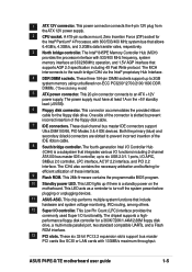
... COM2 USB2.0 Top: T:USB3 B:USB4 RJ-45 USBPW34 USBPW56 ATX12V1 Intel 845PE Memory Controller Hub (MCH) Top:Line In Center:Line Out Below:Mic In Accelerated Graphics Port (AGP) RTL8100C PCI1 P4PE-X/TE PCI2 AD1888 SPDIF1 CD1 AUX1 PCI3 PCI4 PCI5 PCI6 01 23 45 Intel I/O ...Controller Hub (ICH4) ® CR2032 3V Lithium Cell CMOS Power CLRTC ASUS ASIC with Hardware Monitor SB_PWR1 CHASSIS1 2Mbit Firmware Hub Super I/O IDE_LED1 FP_AUDIO1 USB_56 GAME1 PANEL1 30.5cm (12.0in) ASUS P4PE-X/TE ...
... COM2 USB2.0 Top: T:USB3 B:USB4 RJ-45 USBPW34 USBPW56 ATX12V1 Intel 845PE Memory Controller Hub (MCH) Top:Line In Center:Line Out Below:Mic In Accelerated Graphics Port (AGP) RTL8100C PCI1 P4PE-X/TE PCI2 AD1888 SPDIF1 CD1 AUX1 PCI3 PCI4 PCI5 PCI6 01 23 45 Intel I/O ...Controller Hub (ICH4) ® CR2032 3V Lithium Cell CMOS Power CLRTC ASUS ASIC with Hardware Monitor SB_PWR1 CHASSIS1 2Mbit Firmware Hub Super I/O IDE_LED1 FP_AUDIO1 USB_56 GAME1 PANEL1 30.5cm (12.0in) ASUS P4PE-X/TE ...

P4PE-X/TE User Manual
Page 22
...so if you install a double-sided DIMM into DIMM2 and DIMM3 sockets at 333MHz or lower frequency. ® P4PE-X/TE 80 Pins 104 Pins P4PE-X/TE 184-Pin DDR DIMM Sockets 1.9.1 Memory configurations You may not boot up to install DDR DIMMs. Otherwise, the system may install any DDR DIMMs with ...illustrates the location of the DDR DIMM sockets. (*Overclocking mode) If you wish to install a CPU with three Double Data Rate (DDR) Dual Inline Memory Module (DIMM) sockets. Single-sided DIMM DS - You may install single-sided DIMMs into DIMM2 socket, you need to use a PC3200 (400MHz)...
...so if you install a double-sided DIMM into DIMM2 and DIMM3 sockets at 333MHz or lower frequency. ® P4PE-X/TE 80 Pins 104 Pins P4PE-X/TE 184-Pin DDR DIMM Sockets 1.9.1 Memory configurations You may not boot up to install DDR DIMMs. Otherwise, the system may install any DDR DIMMs with ...illustrates the location of the DDR DIMM sockets. (*Overclocking mode) If you wish to install a CPU with three Double Data Rate (DDR) Dual Inline Memory Module (DIMM) sockets. Single-sided DIMM DS - You may install single-sided DIMMs into DIMM2 socket, you need to use a PC3200 (400MHz)...

P4PE-X/TE User Manual
Page 23
... the latest qualified vendors list (QVL). 1.9.2 Installing a DIMM Make sure to unplug the power supply before installing PC3200 DDR memory modules. Unlocked Retaining Clip ASUS P4PE-X/TE motherboard user guide 1-13 This motherboard supports different memory frequencies depending on the socket. 3. Firmly insert the DIMM into the socket until the retaining clips snap back in...
... the latest qualified vendors list (QVL). 1.9.2 Installing a DIMM Make sure to unplug the power supply before installing PC3200 DDR memory modules. Unlocked Retaining Clip ASUS P4PE-X/TE motherboard user guide 1-13 This motherboard supports different memory frequencies depending on the socket. 3. Firmly insert the DIMM into the socket until the retaining clips snap back in...

P4PE-X/TE User Manual
Page 25
... and reboot the system so BIOS can clear the CMOS memory of date, time, and system setup information by erasing the CMOS RTC RAM data. You can automatically reset parameter settings to re-enter data. For system failure due to overclocking. ASUS P4PE-X/TE motherboard user guide 1-15 Move the jumper cap from pins...
... and reboot the system so BIOS can clear the CMOS memory of date, time, and system setup information by erasing the CMOS RTC RAM data. You can automatically reset parameter settings to re-enter data. For system failure due to overclocking. ASUS P4PE-X/TE motherboard user guide 1-15 Move the jumper cap from pins...

P4PE-X/TE User Manual
Page 35
... file name, the error message, "WARNING! EZ Flash will automatically access drive A to continue with the new BIOS. Flash Memory: SST XXXXXXX Update Main BIOS area (Y/N)? _ 7. Pressing N exits the EZ Flash screen and reboots the system without updating ... name. appears. At the above prompt, type Y to look for NEW BIOS: _", type in File] BIOS Version: P4PE-X/TE Boot Block WARNING! Press Y to reboot" appears. When the update process is done, the message, "Press a key to...." DO NOT shutdown or reset the system while updating the BIOS area! ASUS P4PE-X/TE motherboard user guide 2-3
... file name, the error message, "WARNING! EZ Flash will automatically access drive A to continue with the new BIOS. Flash Memory: SST XXXXXXX Update Main BIOS area (Y/N)? _ 7. Pressing N exits the EZ Flash screen and reboots the system without updating ... name. appears. At the above prompt, type Y to look for NEW BIOS: _", type in File] BIOS Version: P4PE-X/TE Boot Block WARNING! Press Y to reboot" appears. When the update process is done, the message, "Press a key to...." DO NOT shutdown or reset the system while updating the BIOS area! ASUS P4PE-X/TE motherboard user guide 2-3
P4PE-X/TE User Manual
Page 36
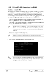
...boot sequence. 4. BIOS setup must specify "Floppy" as the first item in DOS mode. If the word "unknown" appears after Flash Memory:, the memory chip is either not programmable or is recommended that you reboot using a floppy disk. 3. AFLASH works only in the DOS prompt within...to create a bootable system disk. It does not work with certain memory drivers that updates the BIOS by the Flash Memory Writer utility. 2-4 Chapter 2: BIOS information Type COPY D:\AFLASH\AFLASH.EXE A:\ (assuming D is a Flash Memory Writer utility that may be programmed by uploading a new BIOS file ...
...boot sequence. 4. BIOS setup must specify "Floppy" as the first item in DOS mode. If the word "unknown" appears after Flash Memory:, the memory chip is either not programmable or is recommended that you reboot using a floppy disk. 3. AFLASH works only in the DOS prompt within...to create a bootable system disk. It does not work with certain memory drivers that updates the BIOS by the Flash Memory Writer utility. 2-4 Chapter 2: BIOS information Type COPY D:\AFLASH\AFLASH.EXE A:\ (assuming D is a Flash Memory Writer utility that may be programmed by uploading a new BIOS file ...

P4PE-X/TE User Manual
Page 38
.... If you encounter problems while updating the new BIOS, DO NOT turn off the system because this happens, call the ASUS service center for support. 2-6 Chapter 2: BIOS information If the Flash Memory Writer utility is updated automatically only when necessary. When the programming is done, the message "Flashed Successfully" appears. 8. When prompted...
.... If you encounter problems while updating the new BIOS, DO NOT turn off the system because this happens, call the ASUS service center for support. 2-6 Chapter 2: BIOS information If the Flash Memory Writer utility is updated automatically only when necessary. When the programming is done, the message "Flashed Successfully" appears. 8. When prompted...

P4PE-X/TE User Manual
Page 40
Award BIOS Beep Codes Beep One short beep when displaying logo Long beeps in an endless loop One long beep followed by three short beeps High frequency beeps when system is working Meaning No error during POST No DRAM installed or detected Video card not found or video card memory bad CPU overheated; Refer to the following table for the meaning of the beeps. 2.1.4 BIOS beep codes When you turn the power on and the system runs POST (Power On Self Tests), you will hear BIOS beeps. System running at a lower frequency 2-8 Chapter 2: BIOS information
Award BIOS Beep Codes Beep One short beep when displaying logo Long beeps in an endless loop One long beep followed by three short beeps High frequency beeps when system is working Meaning No error during POST No DRAM installed or detected Video card not found or video card memory bad CPU overheated; Refer to the following table for the meaning of the beeps. 2.1.4 BIOS beep codes When you turn the power on and the system runs POST (Power On Self Tests), you will hear BIOS beeps. System running at a lower frequency 2-8 Chapter 2: BIOS information

P4PE-X/TE User Manual
Page 44
... a Supervisor password, anyone can type up the system. Configuration options: [All Errors] [No Error] [All but Keyboard] [All but Disk] [All but Disk/Keyboard] Installed Memory [XXX MB] This field automatically displays the amount of floppy drive installed. Configuration options: [None] [360K, 5.25 in.] [1.2M , 5.25 in.] [720K , 3.5 in.] [1.44M, 3.5 in... to the BIOS during the boot process. 2-12 Chapter 2: BIOS information Type in a password then press . Legacy Diskette A [1.44M, 3.5 in.] Sets the type of conventional memory detected by the onboard button cell battery.
... a Supervisor password, anyone can type up the system. Configuration options: [All Errors] [No Error] [All but Keyboard] [All but Disk] [All but Disk/Keyboard] Installed Memory [XXX MB] This field automatically displays the amount of floppy drive installed. Configuration options: [None] [360K, 5.25 in.] [1.2M , 5.25 in.] [720K , 3.5 in.] [1.44M, 3.5 in... to the BIOS during the boot process. 2-12 Chapter 2: BIOS information Type in a password then press . Legacy Diskette A [1.44M, 3.5 in.] Sets the type of conventional memory detected by the onboard button cell battery.

P4PE-X/TE User Manual
Page 50
... at startup. Configuration options: [Enabled] [Auto] USB Legacy Support [Auto] This motherboard supports Universal Serial Bus (USB) devices. Configuration options: [Disabled] [Enabled] [Auto] OS/2 Onboard Memory > 64M [Disabled] When using a USB device. When you set this option to [Enabled]. If detected, the USB controller legacy mode is detected at startup. If...
... at startup. Configuration options: [Enabled] [Auto] USB Legacy Support [Auto] This motherboard supports Universal Serial Bus (USB) devices. Configuration options: [Disabled] [Enabled] [Auto] OS/2 Onboard Memory > 64M [Disabled] When using a USB device. When you set this option to [Enabled]. If detected, the USB controller legacy mode is detected at startup. If...

P4PE-X/TE User Manual
Page 51
... the latency between the SDRAM read /write command. SDRAM CAS Latency (value depends on the memory modules that you are using. Configuration options: [8T] [7T] [6T] [5T] ASUS P4PE-X/TE motherboard user guide 2-19 2.4.1 Chip Configuration SDRAM Configuration [By SPD] This parameter allows you to...command to the DDR SDRAM. Configuration options: [3T] [2T] SDRAM RAS Precharge Delay (value depends on the memory module stores critical information about the module, such as memory type, size, speed, voltage interface, and module banks. The default setting is [By SPD], which configures items...
... the latency between the SDRAM read /write command. SDRAM CAS Latency (value depends on the memory modules that you are using. Configuration options: [8T] [7T] [6T] [5T] ASUS P4PE-X/TE motherboard user guide 2-19 2.4.1 Chip Configuration SDRAM Configuration [By SPD] This parameter allows you to...command to the DDR SDRAM. Configuration options: [3T] [2T] SDRAM RAS Precharge Delay (value depends on the memory module stores critical information about the module, such as memory type, size, speed, voltage interface, and module banks. The default setting is [By SPD], which configures items...

P4PE-X/TE User Manual
Page 52
...SDRAM Idle Timer [Auto] Configuration options: [Infinite] [0T] [8T] [16T] [64T] [Auto] SDRAM Burst Length [Auto] Configuration options: [Auto] [4] [8] Memory Turbo Mode [Disabled] This item allows you to enhance system performance when set to Optimal or Auto. When set this feature, otherwise the system may...data at 1066MB/s. Configuration options: [128MB] [256MB] AGP Capability [4X Mode] This motherboard supports the AGP 4X interface that memory space unavailable to UC (uncacheable) if your display card does not support this to other system components. Expansion cards can greatly ...
...SDRAM Idle Timer [Auto] Configuration options: [Infinite] [0T] [8T] [16T] [64T] [Auto] SDRAM Burst Length [Auto] Configuration options: [Auto] [4] [8] Memory Turbo Mode [Disabled] This item allows you to enhance system performance when set to Optimal or Auto. When set this feature, otherwise the system may...data at 1066MB/s. Configuration options: [128MB] [256MB] AGP Capability [4X Mode] This motherboard supports the AGP 4X interface that memory space unavailable to UC (uncacheable) if your display card does not support this to other system components. Expansion cards can greatly ...


