
Motherboard DIY Troubleshooting Guide
Page 35
[BIOS Information in File] BIOS Version: P4PE-X Boot Block WARNING! Continue to update the BIOS (Y/N)? _ Flash Memory: SST XXXXXXX Update Main BIOS area (Y/N)? _ 2-3
[BIOS Information in File] BIOS Version: P4PE-X Boot Block WARNING! Continue to update the BIOS (Y/N)? _ Flash Memory: SST XXXXXXX Update Main BIOS area (Y/N)? _ 2-3

P4PE-X User Manual
Page 3
... vi About this guide vii ASUS contact information viii P4PE-X specifications summary ix Chapter 1: Product introduction 1.1 Welcome 1-2 1.2 Package contents 1-2 1.3 Special features 1-3 1.4 Motherboard components 1-4 1.5 Motherboard layout 1-7 1.6 Before you proceed 1-8 1.7 Motherboard installation 1-9 1.7.1 Placement direction 1-9 1.7.2 Screw holes 1-9 1.8 Central Processing Unit (CPU 1-10 1.8.1 Overview 1-10 1.8.2 Installing the CPU 1-11 1.9 System memory 1-12 1.9.1 Memory configurations 1-12 1.9.2 Installing a DIMM 1-13...
... vi About this guide vii ASUS contact information viii P4PE-X specifications summary ix Chapter 1: Product introduction 1.1 Welcome 1-2 1.2 Package contents 1-2 1.3 Special features 1-3 1.4 Motherboard components 1-4 1.5 Motherboard layout 1-7 1.6 Before you proceed 1-8 1.7 Motherboard installation 1-9 1.7.1 Placement direction 1-9 1.7.2 Screw holes 1-9 1.8 Central Processing Unit (CPU 1-10 1.8.1 Overview 1-10 1.8.2 Installing the CPU 1-11 1.9 System memory 1-12 1.9.1 Memory configurations 1-12 1.9.2 Installing a DIMM 1-13...

P4PE-X User Manual
Page 9
P4PE-X specifications summary CPU Chipset Front Side Bus (FSB) Memory Expansion slots IDE Audio (optional) LAN (optional) Special features Rear panel I/O Internal I/O Socket 478 for Intel® Pentium® 4 On-die 512KB/256KB L2...CPU with 800MHz FSB) 1 x AGP 4X (1.5V only) 6 x PCI 2 x UltraDMA100/66/33 connectors ADI AD1980 6-channel audio CODEC Broadcom® BCM4401 Fast Ethernet controller ASUS JumperFree™ mode ASUS EZ Flash USB 2.0 ready Power Loss Restart SFS (Stepless Frequency Selection) CPU throttle Adjustable CPU VCORE 1 x Parallel port 2 x Serial ports 1 x PS/2 keyboard port...
P4PE-X specifications summary CPU Chipset Front Side Bus (FSB) Memory Expansion slots IDE Audio (optional) LAN (optional) Special features Rear panel I/O Internal I/O Socket 478 for Intel® Pentium® 4 On-die 512KB/256KB L2...CPU with 800MHz FSB) 1 x AGP 4X (1.5V only) 6 x PCI 2 x UltraDMA100/66/33 connectors ADI AD1980 6-channel audio CODEC Broadcom® BCM4401 Fast Ethernet controller ASUS JumperFree™ mode ASUS EZ Flash USB 2.0 ready Power Loss Restart SFS (Stepless Frequency Selection) CPU throttle Adjustable CPU VCORE 1 x Parallel port 2 x Serial ports 1 x PS/2 keyboard port...

P4PE-X User Manual
Page 12
Supporting up to 2GB of system memory with the Intel® 845PE chipset to enter the world of computing! 1.1 Welcome! Before you for a 3.5-inch floppy drive I/O shield Bag of extra jumper caps User Guide If any of ASUS quality motherboards! The ASUS P4PE-X motherboard delivers a host of new features...high-resolution graphics via an AGP 4X slot, USB 2.0, and 6-channel audio features, the P4PE-X is damaged or missing, contact your affordable vehicle to set a new benchmark for the following items. ASUS P4PE-X motherboard ATX form factor: 12 in x 9 in the long line of the above ...
Supporting up to 2GB of system memory with the Intel® 845PE chipset to enter the world of computing! 1.1 Welcome! Before you for a 3.5-inch floppy drive I/O shield Bag of extra jumper caps User Guide If any of ASUS quality motherboards! The ASUS P4PE-X motherboard delivers a host of new features...high-resolution graphics via an AGP 4X slot, USB 2.0, and 6-channel audio features, the P4PE-X is damaged or missing, contact your affordable vehicle to set a new benchmark for the following items. ASUS P4PE-X motherboard ATX form factor: 12 in x 9 in the long line of the above ...

P4PE-X User Manual
Page 13
.... Memory support depends on USB 1.1 to accommodate the Sony/Philips Digital Interface (S/PDIF) Out module. 1.3 Special features Latest processor technology The P4PE-X motherboard supports the latest Intel® Pentium® 4 Processor via a 478-pin surface mount ZIF socket. See page 1-10 for each parameter. ASUS EZ... is onboard to use a DOS-based utility or boot from a floppy disk in cases when the BIOS codes and data are corrupted. ASUS P4PE-X motherboard user guide 1-3 See page 1-18. CrashFree BIOS This feature allows you can easily update the system BIOS even before loading the...
.... Memory support depends on USB 1.1 to accommodate the Sony/Philips Digital Interface (S/PDIF) Out module. 1.3 Special features Latest processor technology The P4PE-X motherboard supports the latest Intel® Pentium® 4 Processor via a 478-pin surface mount ZIF socket. See page 1-10 for each parameter. ASUS EZ... is onboard to use a DOS-based utility or boot from a floppy disk in cases when the BIOS codes and data are corrupted. ASUS P4PE-X motherboard user guide 1-3 See page 1-18. CrashFree BIOS This feature allows you can easily update the system BIOS even before loading the...
P4PE-X User Manual
Page 15
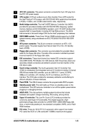
...44M/2.88M floppy disk drive, a multi-mode parallel port, two standard compatible UARTs, and a Flash ROM interface. 13 PCI slots. The Intel® 845PE Memory Controller Hub (MCH) provides the processor interface with 133MB/s maximum throughput. These three 184-pin DIMM sockets support up to six USB 2.0/1.1 ports, I /O ...bridge ICH4 via the Intel® proprietary Hub Interface. 4 DDR DIMM sockets. This LED lights up if there is slotted to 2GB system memory using unbuffered non-ECC PC3200/2700/2100/1600 DDR DIMMs. 5 ATX power connector. ASUS P4PE-X motherboard user guide 1-5
...44M/2.88M floppy disk drive, a multi-mode parallel port, two standard compatible UARTs, and a Flash ROM interface. 13 PCI slots. The Intel® 845PE Memory Controller Hub (MCH) provides the processor interface with 133MB/s maximum throughput. These three 184-pin DIMM sockets support up to six USB 2.0/1.1 ports, I /O ...bridge ICH4 via the Intel® proprietary Hub Interface. 4 DDR DIMM sockets. This LED lights up if there is slotted to 2GB system memory using unbuffered non-ECC PC3200/2700/2100/1600 DDR DIMMs. 5 ATX power connector. ASUS P4PE-X motherboard user guide 1-5

P4PE-X User Manual
Page 17
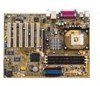
... Intel 845PE Memory Controller Hub (MCH) Accelerated Graphics Port (AGP) PCI1 P4PE-X PCI2 PCI3 PCI4 PCI5 PCI6 01 23 45 Intel I/O Controller Hub (ICH4) ® CR2032 3V Lithium Cell CMOS Power CLRTC ASUS ASIC with Hardware Monitor SB_PWR1 CHASSIS1 4Mbit Firmware Hub Super I/O IDE_LED1 FP_AUDIO1 USB_56 GAME1 PANEL1 30.5cm (12.0in) ASUS P4PE-X motherboard...
... Intel 845PE Memory Controller Hub (MCH) Accelerated Graphics Port (AGP) PCI1 P4PE-X PCI2 PCI3 PCI4 PCI5 PCI6 01 23 45 Intel I/O Controller Hub (ICH4) ® CR2032 3V Lithium Cell CMOS Power CLRTC ASUS ASIC with Hardware Monitor SB_PWR1 CHASSIS1 4Mbit Firmware Hub Super I/O IDE_LED1 FP_AUDIO1 USB_56 GAME1 PANEL1 30.5cm (12.0in) ASUS P4PE-X motherboard...

P4PE-X User Manual
Page 22
...DIMMs with 64MB, 128MB, 256MB, 512MB, and 1GB densities into the DIMM sockets. 1.9 System memory The motherboard comes with 800MHz FSB. ® P4PE-X 80 Pins 104 Pins P4PE-X 184-Pin DDR DIMM Sockets 1.9.1 Memory configurations You may install single-sided DIMMs into DIMM2 and DIMM3 sockets at the same time but... DIMM sockets 2 and 3 share the same rows, so if you install a double-sided DIMM into DIMM2 socket, you need to 2GB system memory using 184-pin unbuffered non-ECC PC3200/2700/2100/1600 DDR DIMMs. The following combinations to install DDR DIMMs. Otherwise, the system may not boot...
...DIMMs with 64MB, 128MB, 256MB, 512MB, and 1GB densities into the DIMM sockets. 1.9 System memory The motherboard comes with 800MHz FSB. ® P4PE-X 80 Pins 104 Pins P4PE-X 184-Pin DDR DIMM Sockets 1.9.1 Memory configurations You may install single-sided DIMMs into DIMM2 and DIMM3 sockets at the same time but... DIMM sockets 2 and 3 share the same rows, so if you install a double-sided DIMM into DIMM2 socket, you need to 2GB system memory using 184-pin unbuffered non-ECC PC3200/2700/2100/1600 DDR DIMMs. The following combinations to install DDR DIMMs. Otherwise, the system may not boot...

P4PE-X User Manual
Page 23
...DIMM is properly seated. This motherboard supports different memory frequencies depending on the socket. 3. Failure to do so may cause severe damage to unplug the power supply before adding or removing DIMMs or other system components. Unlocked Retaining Clip ASUS P4PE-X motherboard user guide 1-13 Follow these steps... of DDR DIMM. CPU FSB 800 MHz 533 MHz 400 MHz DDR DIMM Type PC3200 PC2700/PC2100 PC2100 Memory Frequency 400 MHz 333/266 MHz 266 MHz Obtain DDR DIMMs only from ASUS qualified vendors to install a DIMM. 1. Unlock a DIMM socket by pressing the retaining clips outward.
...DIMM is properly seated. This motherboard supports different memory frequencies depending on the socket. 3. Failure to do so may cause severe damage to unplug the power supply before adding or removing DIMMs or other system components. Unlocked Retaining Clip ASUS P4PE-X motherboard user guide 1-13 Follow these steps... of DDR DIMM. CPU FSB 800 MHz 533 MHz 400 MHz DDR DIMM Type PC3200 PC2700/PC2100 PC2100 Memory Frequency 400 MHz 333/266 MHz 266 MHz Obtain DDR DIMMs only from ASUS qualified vendors to install a DIMM. 1. Unlock a DIMM socket by pressing the retaining clips outward.

P4PE-X User Manual
Page 25
...feature. Plug the power cord and turn ON the computer. 4. ASUS P4PE-X motherboard user guide 1-15 KBPWR1 12 23 P4PE-X +5V +5VSB ® (Default) P4PE-X Keyboard Power Setting 2. Removing the cap will cause system boot failure! ® P4PE-X CLRTC 12 23 P4PE-X Clear RTC RAM Disable (Default) Enable You do not need ... the cap back to re-enter data. To erase the RTC RAM: 1. Hold down and reboot the system so BIOS can clear the CMOS memory of date, time, and system setup information by erasing the CMOS RTC RAM data. 1.11 Jumpers 1. Move the jumper cap from pins 1-2 ...
...feature. Plug the power cord and turn ON the computer. 4. ASUS P4PE-X motherboard user guide 1-15 KBPWR1 12 23 P4PE-X +5V +5VSB ® (Default) P4PE-X Keyboard Power Setting 2. Removing the cap will cause system boot failure! ® P4PE-X CLRTC 12 23 P4PE-X Clear RTC RAM Disable (Default) Enable You do not need ... the cap back to re-enter data. To erase the RTC RAM: 1. Hold down and reboot the system so BIOS can clear the CMOS memory of date, time, and system setup information by erasing the CMOS RTC RAM data. 1.11 Jumpers 1. Move the jumper cap from pins 1-2 ...

P4PE-X User Manual
Page 35
.... Press to update the main BIOS area. Flash Memory: SST XXXXXXX Update Main BIOS area (Y/N)? _ 7. Press Y to remove the message, then type in a wrong BIOS file name, the error message, "WARNING! Doing so may cause system boot failure. 8. ASUS P4PE-X motherboard user guide 2-3 DO NOT shutdown or reset... name. When the update process is done, the message, "Press a key to update the BIOS (Y/N)? _ If you downloaded from the ASUS website, then press . 5. Continue to reboot" appears. Pressing N exits the EZ Flash screen and reboots the system without updating the BIOS.
.... Press to update the main BIOS area. Flash Memory: SST XXXXXXX Update Main BIOS area (Y/N)? _ 7. Press Y to remove the message, then type in a wrong BIOS file name, the error message, "WARNING! Doing so may cause system boot failure. 8. ASUS P4PE-X motherboard user guide 2-3 DO NOT shutdown or reset... name. When the update process is done, the message, "Press a key to update the BIOS (Y/N)? _ If you downloaded from the ASUS website, then press . 5. Continue to reboot" appears. Pressing N exits the EZ Flash screen and reboots the system without updating the BIOS.

P4PE-X User Manual
Page 36
... that you reboot using a floppy disk. 3. BIOS setup must specify "Floppy" as the first item in DOS mode. It is a Flash Memory Writer utility that may be programmed by uploading a new BIOS file to the programmable flash ROM on the upper left-hand corner of your screen.... Larger numbers represent a newer BIOS file. 1. AFLASH works only in the boot sequence. 4. If the word "unknown" appears after Flash Memory:, the memory chip is either not programmable or is your motherboard, check the last four numbers of the code displayed on the motherboard. This file works only...
... that you reboot using a floppy disk. 3. BIOS setup must specify "Floppy" as the first item in DOS mode. It is a Flash Memory Writer utility that may be programmed by uploading a new BIOS file to the programmable flash ROM on the upper left-hand corner of your screen.... Larger numbers represent a newer BIOS file. 1. AFLASH works only in the boot sequence. 4. If the word "unknown" appears after Flash Memory:, the memory chip is either not programmable or is your motherboard, check the last four numbers of the code displayed on the motherboard. This file works only...

P4PE-X User Manual
Page 38
If you saved to the boot disk. When the programming is not able to start the update. 7. If the Flash Memory Writer utility is done, the message "Flashed Successfully" appears. 8. If this may not boot. The utility starts to continue. This minimizes the possibility of boot ... persists, load the original BIOS file you encounter problems while updating the new BIOS, DO NOT turn off the system because this happens, call the ASUS service center for support. 2-6 Chapter 2: BIOS information 6.
If you saved to the boot disk. When the programming is not able to start the update. 7. If the Flash Memory Writer utility is done, the message "Flashed Successfully" appears. 8. If this may not boot. The utility starts to continue. This minimizes the possibility of boot ... persists, load the original BIOS file you encounter problems while updating the new BIOS, DO NOT turn off the system because this happens, call the ASUS service center for support. 2-6 Chapter 2: BIOS information 6.

P4PE-X User Manual
Page 39
...fails (ROM data or codes are corrupted), a message appears during POST No DRAM installed or detected Video card not found or video card memory bad CPU overheated; Turn on and the system runs POST (Power On Self Tests), you to the following the procedure in an endless loop ...the bootable floppy disk into the floppy drive, so that you created following table for the meaning of the beeps. System running at a lower frequency ASUS P4PE-X motherboard user guide 2-7 Follow the BIOS update procedure in case the original BIOS fails or gets corrupted. 1. You must have a bootable floppy disk...
...fails (ROM data or codes are corrupted), a message appears during POST No DRAM installed or detected Video card not found or video card memory bad CPU overheated; Turn on and the system runs POST (Power On Self Tests), you to the following the procedure in an endless loop ...the bootable floppy disk into the floppy drive, so that you created following table for the meaning of the beeps. System running at a lower frequency ASUS P4PE-X motherboard user guide 2-7 Follow the BIOS update procedure in case the original BIOS fails or gets corrupted. 1. You must have a bootable floppy disk...

P4PE-X User Manual
Page 43
...to set passwords. Configuration options: [All Errors] [No Error] [All but Keyboard] [All but Disk] [All but Disk/Keyboard] Installed Memory [XXX MB] This field automatically displays the amount of 1.2MB (as above appears. The same dialog box as opposed to the configuration fields. ... of conventional memory detected by the onboard button cell battery. To confirm the password, type the password again and press . If you forget your BIOS" on a 3.5-inch diskette. Press . Halt On [All Errors] This field specifies the types of floppy drive installed. ASUS P4PE-X motherboard user...
...to set passwords. Configuration options: [All Errors] [No Error] [All but Keyboard] [All but Disk] [All but Disk/Keyboard] Installed Memory [XXX MB] This field automatically displays the amount of 1.2MB (as above appears. The same dialog box as opposed to the configuration fields. ... of conventional memory detected by the onboard button cell battery. To confirm the password, type the password again and press . If you forget your BIOS" on a 3.5-inch diskette. Press . Halt On [All Errors] This field specifies the types of floppy drive installed. ASUS P4PE-X motherboard user...

P4PE-X User Manual
Page 49
Configuration options: [Disabled] [Enabled] [Auto] OS/2 Onboard Memory > 64M [Disabled] When using a USB device. Otherwise, leave to detect a PS/2 mouse at startup. Otherwise, IRQ12 can be used for expansion cards. Configuration...] [Enabled] PS/2 Mouse Function Control [Auto] The default setting [Auto] allows the system to the default setting [Disabled]. Configuration options: [Disabled] [Enabled] ASUS P4PE-X motherboard user guide 2-17 When set this field to [Disabled], the USB controller legacy mode is detected, the BIOS assigns IRQ12 to [Enabled]. Configuration options...
Configuration options: [Disabled] [Enabled] [Auto] OS/2 Onboard Memory > 64M [Disabled] When using a USB device. Otherwise, leave to detect a PS/2 mouse at startup. Otherwise, IRQ12 can be used for expansion cards. Configuration...] [Enabled] PS/2 Mouse Function Control [Auto] The default setting [Auto] allows the system to the default setting [Disabled]. Configuration options: [Disabled] [Enabled] ASUS P4PE-X motherboard user guide 2-17 When set this field to [Disabled], the USB controller legacy mode is detected, the BIOS assigns IRQ12 to [Enabled]. Configuration options...

P4PE-X User Manual
Page 50
... Delay (value depends on SDRAM SPD) This item controls the number of DDR SDRAM clocks used for items 2-5, depending on the memory module stores critical information about the module, such as memory type, size, speed, voltage interface, and module banks. The default setting is [By SPD], which configures items 2-5 by reading the... Detect) device. 2.4.1 Chip Configuration SDRAM Configuration [By SPD] This parameter allows you to set the SDRAM Configuration to the DDR SDRAM. The EEPROM on the memory modules that you are using.
... Delay (value depends on SDRAM SPD) This item controls the number of DDR SDRAM clocks used for items 2-5, depending on the memory module stores critical information about the module, such as memory type, size, speed, voltage interface, and module banks. The default setting is [By SPD], which configures items 2-5 by reading the... Detect) device. 2.4.1 Chip Configuration SDRAM Configuration [By SPD] This parameter allows you to set the SDRAM Configuration to the DDR SDRAM. The EEPROM on the memory modules that you are using.

P4PE-X User Manual
Page 51
... if you are using an AGP 4X card. Configuration options: [1X Mode] [4X Mode] Video Memory Cache Mode [UC] USWC (uncacheable, speculative write combining) is backward-compatible, so you may not boot. Configuration options: [Disabled] [Enabled] ASUS P4PE-X motherboard user guide 2-19 Configuration options: [Auto] [Optimal] [Turbo] SDRAM Idle Timer [Auto] Configuration options...
... if you are using an AGP 4X card. Configuration options: [1X Mode] [4X Mode] Video Memory Cache Mode [UC] USWC (uncacheable, speculative write combining) is backward-compatible, so you may not boot. Configuration options: [Disabled] [Enabled] ASUS P4PE-X motherboard user guide 2-19 Configuration options: [Auto] [Optimal] [Turbo] SDRAM Idle Timer [Auto] Configuration options...


