
Motherboard DIY Troubleshooting Guide
Page 1
® P4PE-X Motherboard
® P4PE-X Motherboard

P4PE-X User Manual
Page 1
Motherboard P4PE-X User Guide
Motherboard P4PE-X User Guide

P4PE-X User Manual
Page 3
Features Contents Notices v Safety information vi About this guide vii ASUS contact information viii P4PE-X specifications summary ix Chapter 1: Product introduction 1.1 Welcome 1-2 1.2 Package contents 1-2 1.3 Special features 1-3 1.4 Motherboard components 1-4 1.5 Motherboard layout 1-7 1.6 Before you proceed 1-8 1.7 Motherboard installation 1-9 1.7.1 Placement direction 1-9 1.7.2 Screw holes 1-9 1.8 Central Processing Unit (CPU 1-10 1.8.1 Overview 1-10 1.8.2 Installing the CPU 1-11 1.9 System memory 1-12 1.9.1 Memory configurations 1-12...
Features Contents Notices v Safety information vi About this guide vii ASUS contact information viii P4PE-X specifications summary ix Chapter 1: Product introduction 1.1 Welcome 1-2 1.2 Package contents 1-2 1.3 Special features 1-3 1.4 Motherboard components 1-4 1.5 Motherboard layout 1-7 1.6 Before you proceed 1-8 1.7 Motherboard installation 1-9 1.7.1 Placement direction 1-9 1.7.2 Screw holes 1-9 1.8 Central Processing Unit (CPU 1-10 1.8.1 Overview 1-10 1.8.2 Installing the CPU 1-11 1.9 System memory 1-12 1.9.1 Memory configurations 1-12...

P4PE-X User Manual
Page 6
...not try to or from the system, ensure that all power cables are using, contact your area. Operation safety • Before installing the motherboard and adding devices on a stable surface. • If you are unplugged. • Seek professional assistance before using an adpater or extension ... in any damage, contact your retailer. vi If you add a device. • Before connecting or removing signal cables from the motherboard, ensure that the power cables for the devices are unplugged before the signal cables are not damaged. These devices could interrupt the grounding...
...not try to or from the system, ensure that all power cables are using, contact your area. Operation safety • Before installing the motherboard and adding devices on a stable surface. • If you are unplugged. • Seek professional assistance before using an adpater or extension ... in any damage, contact your retailer. vi If you add a device. • Before connecting or removing signal cables from the motherboard, ensure that the power cables for the devices are unplugged before the signal cables are not damaged. These devices could interrupt the grounding...

P4PE-X User Manual
Page 11
Product introduction Chapter 1 This chapter describes the features of the layout, jumper settings, and connectors. It includes brief descriptions of the motherboard components, and illustrations of the P4PE-X motherboard.
Product introduction Chapter 1 This chapter describes the features of the layout, jumper settings, and connectors. It includes brief descriptions of the motherboard components, and illustrations of the P4PE-X motherboard.

P4PE-X User Manual
Page 12
... your retailer. 1-2 Chapter 1: Product introduction Supporting up to enter the world of ASUS quality motherboards! The motherboard incorporates the Intel® Pentium® 4 Processor in 478-pin package coupled with the list below. 1.2 Package contents Check your P4PE-X package for the following items. ASUS P4PE-X motherboard ATX form factor: 12 in x 9 in the long line of computing...
... your retailer. 1-2 Chapter 1: Product introduction Supporting up to enter the world of ASUS quality motherboards! The motherboard incorporates the Intel® Pentium® 4 Processor in 478-pin package coupled with the list below. 1.2 Package contents Check your P4PE-X package for the following items. ASUS P4PE-X motherboard ATX form factor: 12 in x 9 in the long line of computing...

P4PE-X User Manual
Page 13
...data are corrupted. Simply restart the system and the BIOS will automatically restore the CPU default setting for the CPU and DIMM requirements. ASUS P4PE-X motherboard user guide 1-3 A digital audio connector is onboard to buy a replacement ROM chip. C.P.R. (CPU Parameter Recall) When the system ...mount ZIF socket. DDR memory support Employing the Double Data Rate (DDR) memory technology, the P4PE-X motherboard supports up to support 10BASE-T/100BASE-TX networking protocol. ASUS EZ Flash BIOS With the ASUS EZ Flash, you to a fast 480 Mbps on USB 1.1 to restore the original BIOS...
...data are corrupted. Simply restart the system and the BIOS will automatically restore the CPU default setting for the CPU and DIMM requirements. ASUS P4PE-X motherboard user guide 1-3 A digital audio connector is onboard to buy a replacement ROM chip. C.P.R. (CPU Parameter Recall) When the system ...mount ZIF socket. DDR memory support Employing the Double Data Rate (DDR) memory technology, the P4PE-X motherboard supports up to support 10BASE-T/100BASE-TX networking protocol. ASUS EZ Flash BIOS With the ASUS EZ Flash, you to a fast 480 Mbps on USB 1.1 to restore the original BIOS...

P4PE-X User Manual
Page 14
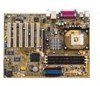
1.4 Motherboard components Before you install the motherboard, learn about its major components and available features to the succeeding pages for the component descriptions. 1 23 4 5 6 7 16 15 8 14 13 17 26 25 1-4 12 11 10 9 18 19 20 21 22 24 23 Chapter 1: Product introduction Refer to facilitate the installation and future upgrades.
1.4 Motherboard components Before you install the motherboard, learn about its major components and available features to the succeeding pages for the component descriptions. 1 23 4 5 6 7 16 15 8 14 13 17 26 25 1-4 12 11 10 9 18 19 20 21 22 24 23 Chapter 1: Product introduction Refer to facilitate the installation and future upgrades.
P4PE-X User Manual
Page 15
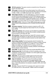
...360K/720K/1.44M/2.88M floppy disk drive, a multi-mode parallel port, two standard compatible UARTs, and a Flash ROM interface. 13 PCI slots. ASUS P4PE-X motherboard user guide 1-5 A 478-pin surface mount, Zero Insertion Force (ZIF) socket for the floppy disk drive. The Intel® 845PE Memory ...Controller Hub (MCH) provides the processor interface with 800/533/400 MHz frequency, system memory interface at least 1A on the motherboard. This connector accommodates the provided ribbon cable for the Intel® Pentium® 4 Processor, with 133MB/s maximum throughput. One side...
...360K/720K/1.44M/2.88M floppy disk drive, a multi-mode parallel port, two standard compatible UARTs, and a Flash ROM interface. 13 PCI slots. ASUS P4PE-X motherboard user guide 1-5 A 478-pin surface mount, Zero Insertion Force (ZIF) socket for the floppy disk drive. The Intel® 845PE Memory ...Controller Hub (MCH) provides the processor interface with 800/533/400 MHz frequency, system memory interface at least 1A on the motherboard. This connector accommodates the provided ribbon cable for the Intel® Pentium® 4 Processor, with 133MB/s maximum throughput. One side...

P4PE-X User Manual
Page 17
SEC_IDE PRI_IDE ATX Power Connector FLOPPY1 1.5 Motherboard layout PS/2KBMS T: Mouse B: Keyboard USB2.0 T: USB4 B: USB3 COM1 KBPWR1 22.86cm (9.0in) Socket 478 CPU_FAN1 CHA_FAN1 DDR DIMM1 (64/72 bit, 184-pin module) ... Memory Controller Hub (MCH) Accelerated Graphics Port (AGP) PCI1 P4PE-X PCI2 PCI3 PCI4 PCI5 PCI6 01 23 45 Intel I/O Controller Hub (ICH4) ® CR2032 3V Lithium Cell CMOS Power CLRTC ASUS ASIC with Hardware Monitor SB_PWR1 CHASSIS1 4Mbit Firmware Hub Super I/O IDE_LED1 FP_AUDIO1 USB_56 GAME1 PANEL1 30.5cm (12.0in) ASUS P4PE-X motherboard user guide 1-7
SEC_IDE PRI_IDE ATX Power Connector FLOPPY1 1.5 Motherboard layout PS/2KBMS T: Mouse B: Keyboard USB2.0 T: USB4 B: USB3 COM1 KBPWR1 22.86cm (9.0in) Socket 478 CPU_FAN1 CHA_FAN1 DDR DIMM1 (64/72 bit, 184-pin module) ... Memory Controller Hub (MCH) Accelerated Graphics Port (AGP) PCI1 P4PE-X PCI2 PCI3 PCI4 PCI5 PCI6 01 23 45 Intel I/O Controller Hub (ICH4) ® CR2032 3V Lithium Cell CMOS Power CLRTC ASUS ASIC with Hardware Monitor SB_PWR1 CHASSIS1 4Mbit Firmware Hub Super I/O IDE_LED1 FP_AUDIO1 USB_56 GAME1 PANEL1 30.5cm (12.0in) ASUS P4PE-X motherboard user guide 1-7

P4PE-X User Manual
Page 18
...supply is switched off or the power cord is ON, in sleep mode, or in any component, ensure that you uninstall any motherboard settings. 1. Unplug the power cord from the power supply. Whenever you should shut down the system and unplug the power cable ...the system is detached from the wall socket before you install or remove any motherboard component. ® P4PE-X P4PE-X Onboard LED SB_PWR1 ON Standby Power OFF Powered Off 1-8 Chapter 1: Product introduction Before you install motherboard components or change any component, place it on them due to avoid touching the...
...supply is switched off or the power cord is ON, in sleep mode, or in any component, ensure that you uninstall any motherboard settings. 1. Unplug the power cord from the power supply. Whenever you should shut down the system and unplug the power cable ...the system is detached from the wall socket before you install or remove any motherboard component. ® P4PE-X P4PE-X Onboard LED SB_PWR1 ON Standby Power OFF Powered Off 1-8 Chapter 1: Product introduction Before you install motherboard components or change any component, place it on them due to avoid touching the...

P4PE-X User Manual
Page 19
... chassis as indicated in the correct orientation. Doing so may cause you physical injury and damage motherboard components. 1.7.1 Placement direction When installing the motherboard, make sure that you install the motherboard, study the configuration of the chassis ASUS P4PE-X motherboard user guide 1-9 Failure to the chassis. Do not overtighten the screws! Make sure to ensure that...
... chassis as indicated in the correct orientation. Doing so may cause you physical injury and damage motherboard components. 1.7.1 Placement direction When installing the motherboard, make sure that you install the motherboard, study the configuration of the chassis ASUS P4PE-X motherboard user guide 1-9 Failure to the chassis. Do not overtighten the screws! Make sure to ensure that...

P4PE-X User Manual
Page 20
... for the Intel® Pentium® 4 Processor in BIOS before installing a supported operating system. 4. Under Linux, use the Hyper-Threading Technology on this motherboard: 1. It is set to compile the code. Power up the system and enter BIOS Setup. 1.8 Central Processing Unit (CPU) 1.8.1 Overview The... motherboard comes with 800MHz FSB, you need to use a PC3200 (400MHz) DDR module. If you installed a CPU with a surface mount 478-pin Zero Insertion Force ...
... for the Intel® Pentium® 4 Processor in BIOS before installing a supported operating system. 4. Under Linux, use the Hyper-Threading Technology on this motherboard: 1. It is set to compile the code. Power up the system and enter BIOS Setup. 1.8 Central Processing Unit (CPU) 1.8.1 Overview The... motherboard comes with 800MHz FSB, you need to use a PC3200 (400MHz) DDR module. If you installed a CPU with a surface mount 478-pin Zero Insertion Force ...

P4PE-X User Manual
Page 21
...; angle, otherwise the CPU does not fit in one correct orientation. Locate the 478-pin ZIF socket on the motherboard. The lever clicks on the side tab to the CPU_FAN1 connector on the motherboard. 2. ASUS P4PE-X motherboard user guide 1-11 When the CPU is lifted up to install a CPU. 1. DO NOT force the CPU into...
...; angle, otherwise the CPU does not fit in one correct orientation. Locate the 478-pin ZIF socket on the motherboard. The lever clicks on the side tab to the CPU_FAN1 connector on the motherboard. 2. ASUS P4PE-X motherboard user guide 1-11 When the CPU is lifted up to install a CPU. 1. DO NOT force the CPU into...

P4PE-X User Manual
Page 22
If you wish to use a PC3200 (400MHz) DDR module, you need to install a CPU with 800MHz FSB. ® P4PE-X 80 Pins 104 Pins P4PE-X 184-Pin DDR DIMM Sockets 1.9.1 Memory configurations You may install any DDR DIMMs with three Double Data Rate (DDR) Dual Inline Memory Module (DIMM) sockets. ... up . Double-sided DIMM DDR DIMM2 (Rows 2&3) DS SS DDR DIMM3 (Rows 3&2) None SS 1. Double-sided 16-bit DDR DIMMs are not supported on this motherboard. 1-12 Chapter 1: Product introduction DDR DIMM1 (Rows 0&1) SS/DS SS/DS * SS - Single-sided DIMM DS - 1.9 System memory The...
If you wish to use a PC3200 (400MHz) DDR module, you need to install a CPU with 800MHz FSB. ® P4PE-X 80 Pins 104 Pins P4PE-X 184-Pin DDR DIMM Sockets 1.9.1 Memory configurations You may install any DDR DIMMs with three Double Data Rate (DDR) Dual Inline Memory Module (DIMM) sockets. ... up . Double-sided DIMM DDR DIMM2 (Rows 2&3) DS SS DDR DIMM3 (Rows 3&2) None SS 1. Double-sided 16-bit DDR DIMMs are not supported on this motherboard. 1-12 Chapter 1: Product introduction DDR DIMM1 (Rows 0&1) SS/DS SS/DS * SS - Single-sided DIMM DS - 1.9 System memory The...

P4PE-X User Manual
Page 23
...do so may cause severe damage to ensure system stability. Unlock a DIMM socket by pressing the retaining clips outward. Unlocked Retaining Clip ASUS P4PE-X motherboard user guide 1-13 DDR DIMM notch 2. Firmly insert the DIMM into the socket until the retaining clips snap back in place and ...the DIMM is properly seated. This motherboard supports different memory frequencies depending on the socket. 3. Follow these steps to unplug the power supply before adding or removing DIMMs or...
...do so may cause severe damage to ensure system stability. Unlock a DIMM socket by pressing the retaining clips outward. Unlocked Retaining Clip ASUS P4PE-X motherboard user guide 1-13 DDR DIMM notch 2. Firmly insert the DIMM into the socket until the retaining clips snap back in place and ...the DIMM is properly seated. This motherboard supports different memory frequencies depending on the socket. 3. Follow these steps to unplug the power supply before adding or removing DIMMs or...
P4PE-X User Manual
Page 24
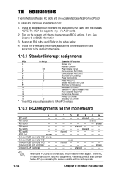
... cards do not need IRQ assignments. When using PCI cards on the system and change the necessary BIOS settings, if any. See Chapter 2 for this motherboard AB PCI slot 1 -- To install and configure an expansion card: 1. Onboard USB controller HC0 shared - 1.10 Expansion slots The...
... cards do not need IRQ assignments. When using PCI cards on the system and change the necessary BIOS settings, if any. See Chapter 2 for this motherboard AB PCI slot 1 -- To install and configure an expansion card: 1. Onboard USB controller HC0 shared - 1.10 Expansion slots The...

P4PE-X User Manual
Page 25
... the RTC RAM: 1. Except when clearing the RTC RAM, never remove the cap on the +5VSB lead, and a corresponding setting in CMOS. ASUS P4PE-X motherboard user guide 1-15 Keyboard power (3-pin KBPWR1) This jumper allows you press a key on pins 2-3 for about 5~10 seconds, then move the ... cap on the keyboard (the default is the Space Bar). KBPWR1 12 23 P4PE-X +5V +5VSB ® (Default) P4PE-X Keyboard Power Setting 2. Removing the cap will cause system boot failure! ® P4PE-X CLRTC 12 23 P4PE-X Clear RTC RAM Disable (Default) Enable You do not need to clear the...
... the RTC RAM: 1. Except when clearing the RTC RAM, never remove the cap on the +5VSB lead, and a corresponding setting in CMOS. ASUS P4PE-X motherboard user guide 1-15 Keyboard power (3-pin KBPWR1) This jumper allows you press a key on pins 2-3 for about 5~10 seconds, then move the ... cap on the keyboard (the default is the Space Bar). KBPWR1 12 23 P4PE-X +5V +5VSB ® (Default) P4PE-X Keyboard Power Setting 2. Removing the cap will cause system boot failure! ® P4PE-X CLRTC 12 23 P4PE-X Clear RTC RAM Disable (Default) Enable You do not need to clear the...

P4PE-X User Manual
Page 26
P4PE-X IDE_LED1 P4PE-X HD Activity LED 2. By default, the pins labeled "Chassis Signal" and "Ground" are shorted with intrusion detection feature. When you wish to light up , try... disk activity LED. 1.12 Connectors This section describes and illustrates the internal connectors on the motherboard. 1. Chassis intrusion connector (4-1 pin CHASSIS1) This lead is for a chassis designed with a jumper cap. CHASSIS1 +5VSB_MB Chassis Signal GND ® P4PE-X P4PE-X Chassis Alarm Lead (Default) 1-16 Chapter 1: Product introduction Hard disk activity LED (2-pin IDE_LED1) ...
P4PE-X IDE_LED1 P4PE-X HD Activity LED 2. By default, the pins labeled "Chassis Signal" and "Ground" are shorted with intrusion detection feature. When you wish to light up , try... disk activity LED. 1.12 Connectors This section describes and illustrates the internal connectors on the motherboard. 1. Chassis intrusion connector (4-1 pin CHASSIS1) This lead is for a chassis designed with a jumper cap. CHASSIS1 +5VSB_MB Chassis Signal GND ® P4PE-X P4PE-X Chassis Alarm Lead (Default) 1-16 Chapter 1: Product introduction Hard disk activity LED (2-pin IDE_LED1) ...

P4PE-X User Manual
Page 27
... for the jumper settings. After connecting one for the primary IDE connector and another UltraDMA/100/66 cable. PIN 1 P4PE-X Floppy Disk Drive Connector ASUS P4PE-X motherboard user guide 1-17 Refer to prevent incorrect insertion when using ribbon cables with two ribbon cables - You may configure two...66 devices to the UltraDMA/100/66 master device. It is intentional. ® P4PE-X NOTE: Orient the red markings (usually zigzag) on the floppy ribbon cable to PIN 1. one end to the motherboard, connect the other end to the floppy drive. (Pin 5 is removed to...
... for the jumper settings. After connecting one for the primary IDE connector and another UltraDMA/100/66 cable. PIN 1 P4PE-X Floppy Disk Drive Connector ASUS P4PE-X motherboard user guide 1-17 Refer to prevent incorrect insertion when using ribbon cables with two ribbon cables - You may configure two...66 devices to the UltraDMA/100/66 master device. It is intentional. ® P4PE-X NOTE: Orient the red markings (usually zigzag) on the floppy ribbon cable to PIN 1. one end to the motherboard, connect the other end to the floppy drive. (Pin 5 is removed to...


