
Motherboard DIY Troubleshooting Guide
Page 1
Motherboard P4PE BP User Guide
Motherboard P4PE BP User Guide

Motherboard DIY Troubleshooting Guide
Page 3
Features Contents Notices v Safety information vi About this guide vii ASUS contact information viii P4PE BP specifications summary ix Chapter 1: Product introduction 1.1 Welcome 1-2 1.2 Package contents 1-2 1.3 Special features 1-3 1.4 Motherboard components 1-4 1.5 Motherboard layout 1-8 1.6 Before you proceed 1-9 1.7 Motherboard installation 1-10 1.7.1 Placement direction 1-10 1.7.2 Screw holes 1-10 1.8 Central Processing Unit (CPU 1-11 1.8.1 Overview 1-11 1.8.2 Installing the CPU 1-12 1.9 System memory 1-13...
Features Contents Notices v Safety information vi About this guide vii ASUS contact information viii P4PE BP specifications summary ix Chapter 1: Product introduction 1.1 Welcome 1-2 1.2 Package contents 1-2 1.3 Special features 1-3 1.4 Motherboard components 1-4 1.5 Motherboard layout 1-8 1.6 Before you proceed 1-9 1.7 Motherboard installation 1-10 1.7.1 Placement direction 1-10 1.7.2 Screw holes 1-10 1.8 Central Processing Unit (CPU 1-11 1.8.1 Overview 1-11 1.8.2 Installing the CPU 1-12 1.9 System memory 1-13...

Motherboard DIY Troubleshooting Guide
Page 6
Contact a qualified service technician or your area. Operation safety • Before installing the motherboard and adding devices on it, carefully read all the manuals that came with the product, contact a qualified service technician or your local power ... correct voltage in any damage, contact your dealer immediately. • To avoid short circuits, keep paper clips, screws, and staples away from the motherboard, ensure that all power cables are unplugged. • Seek professional assistance before the signal cables are connected. vi These devices could interrupt the grounding...
Contact a qualified service technician or your area. Operation safety • Before installing the motherboard and adding devices on it, carefully read all the manuals that came with the product, contact a qualified service technician or your local power ... correct voltage in any damage, contact your dealer immediately. • To avoid short circuits, keep paper clips, screws, and staples away from the motherboard, ensure that all power cables are unplugged. • Seek professional assistance before the signal cables are connected. vi These devices could interrupt the grounding...

Motherboard DIY Troubleshooting Guide
Page 11
It includes brief descriptions of the motherboard components, and illustrations of the P4PE BP motherboard. Chapter 1 This chapter describes the features of the layout, jumper settings, and connectors. Product introduction
It includes brief descriptions of the motherboard components, and illustrations of the P4PE BP motherboard. Chapter 1 This chapter describes the features of the layout, jumper settings, and connectors. Product introduction
Motherboard DIY Troubleshooting Guide
Page 12
... chipset to 2GB of power computing! 1.1 Welcome! Supporting up to set a new benchmark for an effective desktop platform solution. The ASUS P4PE BP motherboard delivers a host of ASUS quality motherboards! Before you for the following items. ASUS P4PE BP motherboard ATX form factor: 12 in x 9 in the long line of new features and latest technologies making it , check the items...
... chipset to 2GB of power computing! 1.1 Welcome! Supporting up to set a new benchmark for an effective desktop platform solution. The ASUS P4PE BP motherboard delivers a host of ASUS quality motherboards! Before you for the following items. ASUS P4PE BP motherboard ATX form factor: 12 in x 9 in the long line of new features and latest technologies making it , check the items...
Motherboard DIY Troubleshooting Guide
Page 13
... the most user-friendly software for more convenient than ever! ASUS P4PE BP motherboard user guide 1-3 With easily removable color-coded pull-tab connectors, connecting devices bacomes an easy task. ASUS Instant Music This unique feature allows you to playback audio files ... design eliminates cable clutter within the chassis, thus optimizing internal airflow. Supporting a USB interface in ASUS motherboards. 3+GHz CPU with Hyper-Threading Technology The P4PE Black Pearl supports the latest Intel® Pentium® 4 Processor with HyperThreading Technology, and new...
... the most user-friendly software for more convenient than ever! ASUS P4PE BP motherboard user guide 1-3 With easily removable color-coded pull-tab connectors, connecting devices bacomes an easy task. ASUS Instant Music This unique feature allows you to playback audio files ... design eliminates cable clutter within the chassis, thus optimizing internal airflow. Supporting a USB interface in ASUS motherboards. 3+GHz CPU with Hyper-Threading Technology The P4PE Black Pearl supports the latest Intel® Pentium® 4 Processor with HyperThreading Technology, and new...

Motherboard DIY Troubleshooting Guide
Page 14
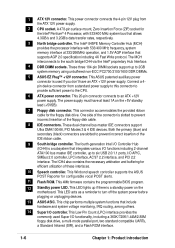
...Floppy disk connector 8. IDE connectors 9. ASUS ASIC 14. PCI slots 16. Microphone jack (optional) 26. Flash ROM 12. RJ-45 port (optional) 23. Line In jack (optional) 24. 1.4 Motherboard components Before you install the motherboard, learn about its major components and... available features to Chapter 2 for detailed information on the components. 1-4 Chapter 1: Product introduction ASUS EZ Plug™ 12V connector 6. Standby power LED...
...Floppy disk connector 8. IDE connectors 9. ASUS ASIC 14. PCI slots 16. Microphone jack (optional) 26. Flash ROM 12. RJ-45 port (optional) 23. Line In jack (optional) 24. 1.4 Motherboard components Before you install the motherboard, learn about its major components and... available features to Chapter 2 for detailed information on the components. 1-4 Chapter 1: Product introduction ASUS EZ Plug™ 12V connector 6. Standby power LED...

Motherboard DIY Troubleshooting Guide
Page 15
1 23 4 5 6 7 8 19 18 17 9 16 15 10 14 13 12 11 20 21 29 28 27 ASUS P4PE BP motherboard user guide 22 23 24 25 26 1-5
1 23 4 5 6 7 8 19 18 17 9 16 15 10 14 13 12 11 20 21 29 28 27 ASUS P4PE BP motherboard user guide 22 23 24 25 26 1-5
Motherboard DIY Troubleshooting Guide
Page 16
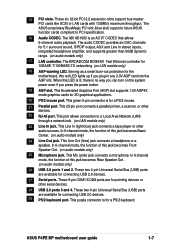
... ports, I/O APIC, SMBus 2.0 controller, LPC interface, AC'97 2.2 interface, and PCI 2.2 interface. This Winbond speech controller supports the ASUS POST Reporter for the floppy disk drive. This chip performs multiple system functions that integrates various I /O controller. The power supply must have an... for the Intel® Pentium® 4 Processor, with 533/400 MHz frequency, system memory interface at least 1A on the motherboard. This ASUS patented auxilliary power connector is a standby power on the +5V standby lead (+5VSB). 7 Floppy disk connector. This Low Pin...
... ports, I/O APIC, SMBus 2.0 controller, LPC interface, AC'97 2.2 interface, and PCI 2.2 interface. This Winbond speech controller supports the ASUS POST Reporter for the floppy disk drive. This chip performs multiple system functions that integrates various I /O controller. The power supply must have an... for the Intel® Pentium® 4 Processor, with 533/400 MHz frequency, system memory interface at least 1A on the motherboard. This ASUS patented auxilliary power connector is a standby power on the +5V standby lead (+5VSB). 7 Floppy disk connector. This Low Pin...
Motherboard DIY Troubleshooting Guide
Page 17
...devices. 29 PS/2 keyboard port. These two 4-pin Universal Serial Bus (USB) ports are available for connecting USB 2.0 devices. 27 Serial ports. ASUS P4PE BP motherboard user guide 1-7 When this LED is lit, there is for a PS/2 keyboard. This port allows connection to PCI specification. 16 Audio CODEC....This purple connector is an AC'97 CODEC that allows 6-channel audio playback. 15 PCI slots. The BROADCOM BCM4401 Fast Ethernet controller for the motherboard, this jack becomes Bass/ Center. (on LAN models only) 23 Line In jack. Serving as a smart burn-out protection for 10BASE-T/...
...devices. 29 PS/2 keyboard port. These two 4-pin Universal Serial Bus (USB) ports are available for connecting USB 2.0 devices. 27 Serial ports. ASUS P4PE BP motherboard user guide 1-7 When this LED is lit, there is for a PS/2 keyboard. This port allows connection to PCI specification. 16 Audio CODEC....This purple connector is an AC'97 CODEC that allows 6-channel audio playback. 15 PCI slots. The BROADCOM BCM4401 Fast Ethernet controller for the motherboard, this jack becomes Bass/ Center. (on LAN models only) 23 Line In jack. Serving as a smart burn-out protection for 10BASE-T/...

Motherboard DIY Troubleshooting Guide
Page 19
...power supply. AGP_WARN1 ® P4PE BP ON Incorrect AGP Card OFF Correct AGP Card SB_PWR1 P4PE BP Onboard LED ON Standby Power OFF Powered Off Install only 1.5V AGP cards on them due to static electricity. 3. If you plug in any motherboard component. The red LED (AGP_WARN1... AGP card. 1.6 Before you proceed Take note of the following precautions before you install motherboard components or change any 3.3V AGP card into the 1.5V AGP slot, this motherboard! ASUS P4PE BP motherboard user guide 1-9 Before you plug in soft-off if you install or remove any component...
...power supply. AGP_WARN1 ® P4PE BP ON Incorrect AGP Card OFF Correct AGP Card SB_PWR1 P4PE BP Onboard LED ON Standby Power OFF Powered Off Install only 1.5V AGP cards on them due to static electricity. 3. If you plug in any motherboard component. The red LED (AGP_WARN1... AGP card. 1.6 Before you proceed Take note of the following precautions before you install motherboard components or change any 3.3V AGP card into the 1.5V AGP slot, this motherboard! ASUS P4PE BP motherboard user guide 1-9 Before you plug in soft-off if you install or remove any component...

Motherboard DIY Troubleshooting Guide
Page 20
... the chassis. Do not overtighten the screws! Make sure to do so may damage the motherboard. Doing so may cause you physical injury and damage motherboard components. 1.7.1 Placement direction When installing the motherboard, make sure that measures 12 inches x 9 inches (30.5 cm x 22.9 cm). ... the chassis 1-10 Chapter 1: Product introduction Failure to unplug the power cord before installing or removing the motherboard. The motherboard uses the ATX form factor that you install the motherboard, study the configuration of the chassis as indicated in the correct orientation.
... the chassis. Do not overtighten the screws! Make sure to do so may damage the motherboard. Doing so may cause you physical injury and damage motherboard components. 1.7.1 Placement direction When installing the motherboard, make sure that measures 12 inches x 9 inches (30.5 cm x 22.9 cm). ... the chassis 1-10 Chapter 1: Product introduction Failure to unplug the power cord before installing or removing the motherboard. The motherboard uses the ATX form factor that you install the motherboard, study the configuration of the chassis as indicated in the correct orientation.
Motherboard DIY Troubleshooting Guide
Page 21
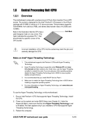
... a supported operating system. 5. Under the Advanced Menu, make sure that the CPU has a gold triangular mark on this motherboard: 1. ASUS P4PE BP motherboard user guide 1-11 To use the Hyper-Threading compliler to Enabled. The item appears only if you install WinXP Service Pack ...1. 4. 1.8 Central Processing Unit (CPU) 1.8.1 Overview The motherboard comes with Hyper-Threading Technology. 2. This motherboard supports Intel Pentium 4 CPUs with a surface mount 478-pin Zero Insertion Force (ZIF) socket. Hyper-Threading...
... a supported operating system. 5. Under the Advanced Menu, make sure that the CPU has a gold triangular mark on this motherboard: 1. ASUS P4PE BP motherboard user guide 1-11 To use the Hyper-Threading compliler to Enabled. The item appears only if you install WinXP Service Pack ...1. 4. 1.8 Central Processing Unit (CPU) 1.8.1 Overview The motherboard comes with Hyper-Threading Technology. 2. This motherboard supports Intel Pentium 4 CPUs with a surface mount 478-pin Zero Insertion Force (ZIF) socket. Hyper-Threading...

Motherboard DIY Troubleshooting Guide
Page 22
... the CPU into the socket to secure the CPU. Gold Mark The CPU fits only in place. Locate the 478-pin ZIF socket on the motherboard. 1-12 Chapter 1: Product introduction Connect the CPU fan cable to indicate that the socket lever is in completely. 90 - 100 3. Install a CPU heatsink ... instructions that its marked corner matches the base of the socket lever. 4. The lever clicks on the side tab to the CPU_FAN1 connector on the motherboard. 2. DO NOT force the CPU into the socket until it is locked. 6. When the CPU is lifted up to install a CPU. 1. Socket Lever ...
... the CPU into the socket to secure the CPU. Gold Mark The CPU fits only in place. Locate the 478-pin ZIF socket on the motherboard. 1-12 Chapter 1: Product introduction Connect the CPU fan cable to indicate that the socket lever is in completely. 90 - 100 3. Install a CPU heatsink ... instructions that its marked corner matches the base of the socket lever. 4. The lever clicks on the side tab to the CPU_FAN1 connector on the motherboard. 2. DO NOT force the CPU into the socket until it is locked. 6. When the CPU is lifted up to install a CPU. 1. Socket Lever ...

Motherboard DIY Troubleshooting Guide
Page 23
... may cause severe damage to unplug the power supply before adding or removing DIMMs or other system components. Unlocked Retaining Clip ASUS P4PE BP motherboard user guide 1-13 Firmly insert the DIMM into the socket until the retaining clips snap back in place and the DIMM.../PC1600 (FSB400) DDR DIMMs. The following figure illustrates the location of the DDR DIMM sockets. ® P4PE BP 80 Pins 104 Pins P4PE BP 184-Pin DDR DIMM Sockets This motherboard supports different memory frequencies depending on the socket. 3. DDR DIMM notch 1. These sockets support up to install...
... may cause severe damage to unplug the power supply before adding or removing DIMMs or other system components. Unlocked Retaining Clip ASUS P4PE BP motherboard user guide 1-13 Firmly insert the DIMM into the socket until the retaining clips snap back in place and the DIMM.../PC1600 (FSB400) DDR DIMMs. The following figure illustrates the location of the DDR DIMM sockets. ® P4PE BP 80 Pins 104 Pins P4PE BP 184-Pin DDR DIMM Sockets This motherboard supports different memory frequencies depending on the socket. 3. DDR DIMM notch 1. These sockets support up to install...

Motherboard DIY Troubleshooting Guide
Page 24
... SS DDR DIMM3 (Rows 3&2) None SS 1. Install an expansion card following combinations to the card documentation. 1-14 Chapter 1: Product introduction Turn on this motherboard. 1.10 Expansion slots The motherboard has three PCI slots and one can be x16 DDR module. 3. Refer to the card. Single-sided DIMM DS - DDR DIMM sockets 2 and...
... SS DDR DIMM3 (Rows 3&2) None SS 1. Install an expansion card following combinations to the card documentation. 1-14 Chapter 1: Product introduction Turn on this motherboard. 1.10 Expansion slots The motherboard has three PCI slots and one can be x16 DDR module. 3. Refer to the card. Single-sided DIMM DS - DDR DIMM sockets 2 and...
Motherboard DIY Troubleshooting Guide
Page 25
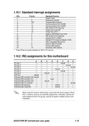
... - - - When using PCI cards on shared slots, ensure that the drivers support "Share IRQ" or that the cards do not need IRQ assignments. shared - - shared - - - - - ASUS P4PE BP motherboard user guide 1-15 Onboard USB controller HC0 shared - Onboard audio (optional) -- PCI slot 2 -- PCI slot 6 -- AGP slot shared - Onboard USB 2.0 controller - - shared - - - - ... usually available for ISA or PCI devices. 1.10.2 IRQ assignments for this motherboard AB PCI slot 1 -- PCI slot 4 -- C D E F GH - - - shared - - shared - - - - - - - - - -- - - - - -- ...
... - - - When using PCI cards on shared slots, ensure that the drivers support "Share IRQ" or that the cards do not need IRQ assignments. shared - - shared - - - - - ASUS P4PE BP motherboard user guide 1-15 Onboard USB controller HC0 shared - Onboard audio (optional) -- PCI slot 2 -- PCI slot 6 -- AGP slot shared - Onboard USB 2.0 controller - - shared - - - - ... usually available for ISA or PCI devices. 1.10.2 IRQ assignments for this motherboard AB PCI slot 1 -- PCI slot 4 -- C D E F GH - - - shared - - shared - - - - - - - - - -- - - - - -- ...
Motherboard DIY Troubleshooting Guide
Page 27
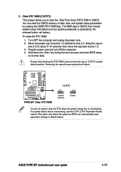
The RAM data in CMOS. Move the jumper cap from pins 1-2 (default) to overclocking, use the C.P.R. (CPU Parameter Recall) feature. ASUS P4PE BP motherboard user guide 1-17 To erase the RTC RAM: 1. Plug the power cord and turn ON the computer. 4. For system failure due to pins 2-3. Keep the... CMOS memory of date, time, and system setup parameters by the onboard button cell battery. 3. Removing the cap will cause system boot failure! ® P4PE BP P4PE BP Clear RTC RAM CLRTC 12 23 Disable (Default) Enable You do not need to clear the RTC when the system hangs due to re-enter...
The RAM data in CMOS. Move the jumper cap from pins 1-2 (default) to overclocking, use the C.P.R. (CPU Parameter Recall) feature. ASUS P4PE BP motherboard user guide 1-17 To erase the RTC RAM: 1. Plug the power cord and turn ON the computer. 4. For system failure due to pins 2-3. Keep the... CMOS memory of date, time, and system setup parameters by the onboard button cell battery. 3. Removing the cap will cause system boot failure! ® P4PE BP P4PE BP Clear RTC RAM CLRTC 12 23 Disable (Default) Enable You do not need to clear the RTC when the system hangs due to re-enter...

Motherboard DIY Troubleshooting Guide
Page 28
... insertion when using ribbon cables with pin 5 plug). PIN 1 P4PE BP Floppy Disk Drive Connector 1-18 Chapter 1: Product introduction IDE_LED1 P4PE BP HD Activity LED 2. P4PE BP TIP: If the case-mounted LED does not ® light up . FLOPPY1 ® P4PE BP NOTE: Orient the red markings on the motherboard. 1. Floppy disk drive connector (34-1 pin FLOPPY) This connector...
... insertion when using ribbon cables with pin 5 plug). PIN 1 P4PE BP Floppy Disk Drive Connector 1-18 Chapter 1: Product introduction IDE_LED1 P4PE BP HD Activity LED 2. P4PE BP TIP: If the case-mounted LED does not ® light up . FLOPPY1 ® P4PE BP NOTE: Orient the red markings on the motherboard. 1. Floppy disk drive connector (34-1 pin FLOPPY) This connector...

Motherboard DIY Troubleshooting Guide
Page 29
It is removed to match the covered hole on the IDE ribbon cable to this connector. ® P4PE BP TRPWR1 Ground TRPWR P4PE BP Power Supply Thermal Connector ASUS P4PE BP motherboard user guide 1-19 one for the primary IDE connector and another UltraDMA/100/66 cable. The hole near ...the blue connector on the UltraDMA/100/66 cable is intentional. ® P4PE BP NOTE: Orient the red markings (usually zigzag)...
It is removed to match the covered hole on the IDE ribbon cable to this connector. ® P4PE BP TRPWR1 Ground TRPWR P4PE BP Power Supply Thermal Connector ASUS P4PE BP motherboard user guide 1-19 one for the primary IDE connector and another UltraDMA/100/66 cable. The hole near ...the blue connector on the UltraDMA/100/66 cable is intentional. ® P4PE BP NOTE: Orient the red markings (usually zigzag)...


