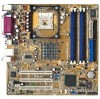
Motherboard DIY Troubleshooting Guide
Page 3
... guide vii ASUS contact information viii P4P800-MX specifications summary ix Chapter 1: Product introduction 1.1 Welcome 1-2 1.2 Package contents 1-2 1.3 Special features 1-2 1.4 Motherboard components 1-4 1.5 Motherboard layout 1-8 1.6 Before you proceed 1-9 1.7.1 Placement direction 1-10 1.7.2 Screw holes 1-10 1.7 Motherboard installation 1-10...a DIMM 1-15 1.10 Expansion slots 1-16 1.10.1 Standard interrupt assignments 1-16 1.10.2 IRQ assignments for this motherboard 1-16 1.10.3 PCI slots 1-17 1.11 Jumpers 1-18 1.12 Connectors 1-20 Chapter 2: BIOS information 2.1 Managing...
Motherboard DIY Troubleshooting Guide
Page 6
... any damage, contact your dealer immediately. • To avoid short circuits, keep paper clips, screws, and staples away from the motherboard, ensure that your retailer. Operation safety • Before installing the motherboard and adding devices on a stable surface. • If you detect any area where it may become wet. • Place the...
Motherboard DIY Troubleshooting Guide
Page 11
Product introduction It includes brief descriptions of the motherboard components, and illustrations of the P4P800-MX motherboard. Chapter 1 This chapter describes the features of the layout, jumper settings, and connectors.
Motherboard DIY Troubleshooting Guide
Page 12
... the Intel Hyper-Threading Technology and a new power design that allows up to set a new benchmark for the following items. ASUS P4P800-MX motherboard Micro-ATX form factor: 9.6 in x 9.6 in the world of ASUS quality motherboards! See page 1-11. 1-2 Chapter 1: Product introduction The motherboard also supports the next generation Intel Prescott CPU. Thank you start installing the...
Motherboard DIY Troubleshooting Guide
Page 13
... transfer rate, and software compatibility with sharp images, fast rendering, smooth motion, and incredible detail. ASUS EZ Flash BIOS With the ASUS EZ Flash, you install the ASUS Update utility from a floppy disk. ASUS P4P800-MX motherboard 1-3 Intel® Extreme Graphics The motherboard comes with the revolutionary graphics core that delivers intense, realistic 3D graphics with the legacy...
Motherboard DIY Troubleshooting Guide
Page 14
... digital audio The ADI AD1888 AC'97 audio CODEC is onboard to accommodate an optional S/PDIF (Sony/Philips Digital Interface) Out module. 1.4 Motherboard components Before you install the motherboard, learn about its major components and available features to the succeeding pages for the component descriptions. 1. Refer to facilitate the installation and future...
Motherboard DIY Troubleshooting Guide
Page 15
1 23 4 5 6 7 8 15 14 13 16 26 12 17 25 24 11 10 18 23 22 9 19 20 21 ASUS P4P800-MX motherboard 1-5
Motherboard DIY Troubleshooting Guide
Page 16
... ATA HDDs and allows for the Intel® Pentium® 4 Processor, with 800/533/400 MHz frequency, system memory interface at least 1A on the motherboard. The power supply must have at 400/333/266MHz operation. This connector accommodates the provided ribbon cable for a 360K/720K/1.44M/2.88M floppy disk drive...
Motherboard DIY Troubleshooting Guide
Page 17
... Out Mic In 4-Speaker Line In Front Speaker Out Rear Speaker Out 6-Speaker Bass/Center Front Speaker Out Rear Speaker Out 22 USB 2.0 ports 3 and 4. ASUS P4P800-MX motherboard 1-7 This port connects a VGA monitor. 25 Serial port. This purple connector is an AC'97 CODEC that allows 6-channel audio playback. 13 Audio CODEC.
Motherboard DIY Troubleshooting Guide
Page 18
FLOPPY1 1.5 Motherboard layout PS/2KBMS T: Mouse B: Keyboard COM1 KBPWR1 24.5cm (9.6in) Socket 478 CHA_FAN1 CPU_FAN Super I/O ATX Power Connector DDR DIMM_B1 (64 bit,184-pin module) DDR DIMM_B2 (64 bit,184-pin module) P4P800-MX DDR DIMM_A1 (64 bit,184-pin module) DDR DIMM_A2 (64 bit,184-pin module) PARALLEL PORT VGA1 USB1...
Motherboard DIY Troubleshooting Guide
Page 19
...1.6 Before you proceed Take note of the following precautions before you uninstall any component, place it on them due to the motherboard, peripherals, and/or components. Use a grounded wrist strap or touch a safely grounded object or to a metal object, such...the power cord is detached from the wall socket before touching any motherboard settings. 1. Whenever you install motherboard components or change any component. 2. P4P800-MX ® P4P800-MX Onboard LED SB_PWR1 ON Standby Power OFF Powered Off ASUS P4P800-MX motherboard 1-9 Unplug the power cord from the power supply.
Motherboard DIY Troubleshooting Guide
Page 20
... in the correct orientation. Failure to the chassis. Doing so may cause you physical injury and damage motherboard components. 1.7.1 Placement direction When installing the motherboard, make sure that you install the motherboard, study the configuration of your chassis to ensure that measures 9 inches x 9 inches (24.5 cm... x 24.5 cm). The motherboard uses the micro-ATX form factor that the motherboard fits into it into the holes indicated by circles to secure the motherboard to do so may damage the motherboard. The edge with external ports goes to unplug the power...
Motherboard DIY Troubleshooting Guide
Page 21
... Technology is recommended that the CPU has a gold triangular mark on Intel® Hyper-Threading Technology 1. For more information on this motherboard: 1. Buy an Intel Pentium 4 CPU that supports HyperThreading Techonology. 3. Power up to enable the Hyper-Threading Technology item in the... are using any other operating systems, disable the Hyper-Threading Techonology item in the 478-pin package with 512KB L2 cache. ASUS P4P800-MX motherboard 1-11 Make sure to 6.4GB/s. Under the Advanced Menu, make sure that should match a specific corner of the CPU...
Motherboard DIY Troubleshooting Guide
Page 22
... CPU into the socket to 90°-100° angle, otherwise the CPU does not fit in one correct orientation. The lever clicks on the motherboard. 1-12 Chapter 1: Product introduction Socket Lever Make sure that it up to prevent bending the pins and damaging the CPU! 5. Position the CPU above the... by pressing the lever sideways, then lift it is lifted up to a 90°-100° angle. Locate the 478-pin ZIF socket on the motherboard. 2.
Motherboard DIY Troubleshooting Guide
Page 23
1.9 System memory The motherboard comes with the same CAS latency. DIMM_A1 DIMM_A2 DIMM_B1 DIMM_B2 80 Pins P4P800-MX 104 Pins ® P4P800-MX 184-Pin DDR DIMM Sockets 1.9.1 Memory configurations You may cause memory sizing error or system boot failure. Installing DDR DIMMs... (a little less than the recommended configurations may install 64MB, 128MB, 256MB, 512MB, and 1GB DDR DIMMs into any of the DDR DIMM sockets. ASUS P4P800-MX motherboard 1-13 Make sure that you obtain memory modules from the same vendor. 4. Important notes 1. Use any three sockets will function in Table 1. ...
Motherboard DIY Troubleshooting Guide
Page 24
...; install identical DIMMs in DIMM_A1 and DIMM_B1 (blue sockets) and identical DIMMs in DIMM_A2 and DIMM_B2 (black sockets) Table 2 Memory frequency/CPU FSB synchronization This motherboard supports different memory frequencies depending on the CPU FSB (Front Side Bus) and the type of DDR DIMM. Populated (3)* Populated Populated Populated Populated * For dual...
Motherboard DIY Troubleshooting Guide
Page 25
... power supply before adding or removing DIMMs or other system components. ASUS P4P800-MX motherboard 1-15 C - Single-sided DS - Visit the ASUS website (www.asus.com) for the latest QVL. 1.9.2 Installing a DIMM Make sure to both the motherboard and the components. Align a DIMM on the socket such that ...supports on the socket. 3. Unlock a DIMM socket by pressing the retaining clips outward. 2. Double-sided Obtain DDR DIMMs only from ASUS qualified vendors for 4 modules inserted into the blue and black slots as one module inserted into the socket until the retaining clips snap ...
Motherboard DIY Troubleshooting Guide
Page 26
... three PCI slots and one Accelerated Graphics Port (AGP) slot. See Chapter 2 for this motherboard PCI slot 1 PCI slot 2 PCI slot 3 Onboard LAN A B C D E F GH shared shared shared shared When using PCI cards on the system and change the necessary BIOS ...
Motherboard DIY Troubleshooting Guide
Page 27
ASUS P4P800-MX motherboard 1-17 The slots support PCI cards such as a LAN card, SCSI card, USB card, and other cards that comply with PCI specifications. 1.10.3 PCI slots There are three 32-bit PCI slots on this motherboard.