
P4GE-VM user manual E1251
Page 1
Motherboard P4GE-VM User Guide
Motherboard P4GE-VM User Guide

P4GE-VM user manual E1251
Page 3
Features Contents Notices v Safety information vi About this guide vii ASUS contact information viii P4GE-VM specifications summary ix Chapter 1: Product introduction 1.1 Welcome 1-2 1.2 Package contents 1-2 1.3 Motherboard components 1-3 1.4 Motherboard layout 1-6 1.5 Before you proceed 1-7 1.6 Motherboard installation 1-8 1.6.1 Placement direction 1-8 1.6.2 Screw holes 1-8 1.7 Central Processing Unit (CPU 1-9 1.7.1 Overview 1-9 1.7.2 Installing the CPU 1-10 1.8 System memory 1-11 1.9 Expansion slots 1-12 1.9.1 Standard interrupt assignments 1-12...
Features Contents Notices v Safety information vi About this guide vii ASUS contact information viii P4GE-VM specifications summary ix Chapter 1: Product introduction 1.1 Welcome 1-2 1.2 Package contents 1-2 1.3 Motherboard components 1-3 1.4 Motherboard layout 1-6 1.5 Before you proceed 1-7 1.6 Motherboard installation 1-8 1.6.1 Placement direction 1-8 1.6.2 Screw holes 1-8 1.7 Central Processing Unit (CPU 1-9 1.7.1 Overview 1-9 1.7.2 Installing the CPU 1-10 1.8 System memory 1-11 1.9 Expansion slots 1-12 1.9.1 Standard interrupt assignments 1-12...

P4GE-VM user manual E1251
Page 6
Operation safety • Before installing the motherboard and adding devices on a stable surface. • If you encounter technical problems with the package. • Before using an adpater or extension cord. If you ... to the correct voltage in any damage, contact your dealer immediately. • To avoid short circuits, keep paper clips, screws, and staples away from the motherboard, ensure that the power cables for the devices are not damaged. Contact a qualified service technician or your area. These devices could interrupt the grounding circuit...
Operation safety • Before installing the motherboard and adding devices on a stable surface. • If you encounter technical problems with the package. • Before using an adpater or extension cord. If you ... to the correct voltage in any damage, contact your dealer immediately. • To avoid short circuits, keep paper clips, screws, and staples away from the motherboard, ensure that the power cables for the devices are not damaged. Contact a qualified service technician or your area. These devices could interrupt the grounding circuit...

P4GE-VM user manual E1251
Page 11
Chapter 1 This chapter describes the features of the layout, jumper settings, and connectors. It includes brief descriptions of the motherboard components, and illustrations of the P4GE-VM motherboard. Product introduction
Chapter 1 This chapter describes the features of the layout, jumper settings, and connectors. It includes brief descriptions of the motherboard components, and illustrations of the P4GE-VM motherboard. Product introduction

P4GE-VM user manual E1251
Page 12
...3.5-inch floppy drive I/O shield Bag of extra jumper caps User Guide If any of the above items is your P4GE-VM package for the following items. ASUS P4GE-VM motherboard Micro-ATX form factor: 9.6 in x 8.6 in your package with the Intel® 845GE chipset to enter ... via an AGP 4X slot, USB 2.0, and 6-channel audio features, the P4GE-VM is damaged or missing, contact your retailer. 1-2 Chapter 1: Product introduction The ASUS P4GE-VM motherboard delivers a host of ASUS quality motherboards! The motherboard incorporates the Intel® Pentium® 4 Processor in the long line of...
...3.5-inch floppy drive I/O shield Bag of extra jumper caps User Guide If any of the above items is your P4GE-VM package for the following items. ASUS P4GE-VM motherboard Micro-ATX form factor: 9.6 in x 8.6 in your package with the Intel® 845GE chipset to enter ... via an AGP 4X slot, USB 2.0, and 6-channel audio features, the P4GE-VM is damaged or missing, contact your retailer. 1-2 Chapter 1: Product introduction The ASUS P4GE-VM motherboard delivers a host of ASUS quality motherboards! The motherboard incorporates the Intel® Pentium® 4 Processor in the long line of...

P4GE-VM user manual E1251
Page 13
1.3 Motherboard components Before you install the motherboard, learn about its major components and available features to the succeeding pages for the component descriptions. 12 34 5 67 8 9 18 17 16 15 19 14 20 13 21 29 28 27 26 25 ASUS P4GE-VM motherboard user guide 10 11 12 22 23 24 1-3 Refer to facilitate the installation and future upgrades.
1.3 Motherboard components Before you install the motherboard, learn about its major components and available features to the succeeding pages for the component descriptions. 12 34 5 67 8 9 18 17 16 15 19 14 20 13 21 29 28 27 26 25 ASUS P4GE-VM motherboard user guide 10 11 12 22 23 24 1-3 Refer to facilitate the installation and future upgrades.

P4GE-VM user manual E1251
Page 15
...power on LAN models only) 22 Line In jack. Serving as a reminder to a Local Area Network (LAN) through a network hub. (on the motherboard. This Intel 82562ET LAN PHY works with 133MB/s maximum throughput. 17 AGP warning LED. This green 6-pin connector is for a PS/2 mouse. 20 ...DAC channels for connecting USB 2.0 devices. 29 PS/2 keyboard port. This port allows connection to turn on audio models only) 16 PCI slots. ASUS P4GE-VM motherboard user guide 1-5 This Mic (pink) jack connects a microphone. This port is no way you plug in the South Bridge (ICH4) to fully ...
...power on LAN models only) 22 Line In jack. Serving as a reminder to a Local Area Network (LAN) through a network hub. (on the motherboard. This Intel 82562ET LAN PHY works with 133MB/s maximum throughput. 17 AGP warning LED. This green 6-pin connector is for a PS/2 mouse. 20 ...DAC channels for connecting USB 2.0 devices. 29 PS/2 keyboard port. This port allows connection to turn on audio models only) 16 PCI slots. ASUS P4GE-VM motherboard user guide 1-5 This Mic (pink) jack connects a microphone. This port is no way you plug in the South Bridge (ICH4) to fully ...

P4GE-VM user manual E1251
Page 16
1.4 Motherboard layout PS/2KBMS T: Mouse B: Keyboard Bottom: USB20-3 USB20-4 COM1 USBPWR_34 KBPWR1 21.9cm (8.6in) ® CPU_FAN1 Socket 478 Super I/O ATX Power Connector FLOPPY1 DDR DIMM1 (... Below:Mic In LAN PHY Accelerated Graphics Port (AGP) 01 23 DIMM1 DIMM2 FP_AUDIO AGP_WARN AUX CD SB_PWR BCS2 BCS1 Audio Codec J6 GAME PCI1 P4GE-VM PCI2 PCI3 COM2 Intel I/O Controller Hub (ICH4) BATTERY1 SMB 2.0 ASUS Mozart USB_56 USBPWR_56 CHASSIS1 IDE_LED ASUS PANEL1 24.4cm (9.6in) 2Mbit Firmware Hub 1-6 Chapter 1: Product introduction
1.4 Motherboard layout PS/2KBMS T: Mouse B: Keyboard Bottom: USB20-3 USB20-4 COM1 USBPWR_34 KBPWR1 21.9cm (8.6in) ® CPU_FAN1 Socket 478 Super I/O ATX Power Connector FLOPPY1 DDR DIMM1 (... Below:Mic In LAN PHY Accelerated Graphics Port (AGP) 01 23 DIMM1 DIMM2 FP_AUDIO AGP_WARN AUX CD SB_PWR BCS2 BCS1 Audio Codec J6 GAME PCI1 P4GE-VM PCI2 PCI3 COM2 Intel I/O Controller Hub (ICH4) BATTERY1 SMB 2.0 ASUS Mozart USB_56 USBPWR_56 CHASSIS1 IDE_LED ASUS PANEL1 24.4cm (9.6in) 2Mbit Firmware Hub 1-6 Chapter 1: Product introduction

P4GE-VM user manual E1251
Page 17
... or plugging in a 1.5V AGP card. ® AGP_WARN P4GE-VM P4GE-VM Onboard LED ON Incorrect AGP Card OFF Correct AGP Card SB_PWR ON Standby Power OFF Powered Off Install only 1.5V AGP cards on this LED lights up . Before you install motherboard components or change any motherboard settings. 1. When lit, the green LED (SB_PWR1) indicates... you install or remove any component, ensure that the ATX power supply is switched off or the power cord is detached from the power supply. ASUS P4GE-VM motherboard user guide 1-7
... or plugging in a 1.5V AGP card. ® AGP_WARN P4GE-VM P4GE-VM Onboard LED ON Incorrect AGP Card OFF Correct AGP Card SB_PWR ON Standby Power OFF Powered Off Install only 1.5V AGP cards on this LED lights up . Before you install motherboard components or change any motherboard settings. 1. When lit, the green LED (SB_PWR1) indicates... you install or remove any component, ensure that the ATX power supply is switched off or the power cord is detached from the power supply. ASUS P4GE-VM motherboard user guide 1-7

P4GE-VM user manual E1251
Page 18
.... Doing so may cause you physical injury and damage motherboard components. 1.6.1 Placement direction When installing the motherboard, make sure that you install the motherboard, study the configuration of your chassis to ensure that the motherboard fits into it into the holes indicated by circles to...ports goes to the rear part of the chassis 1-8 Chapter 1: Product introduction Make sure to do so may damage the motherboard. Do not overtighten the screws! The motherboard uses the micro-ATX form factor that measures 9.6 inches x 8.6 inches (24.5 cm x 21.9 cm). Failure to...
.... Doing so may cause you physical injury and damage motherboard components. 1.6.1 Placement direction When installing the motherboard, make sure that you install the motherboard, study the configuration of your chassis to ensure that the motherboard fits into it into the holes indicated by circles to...ports goes to the rear part of the chassis 1-8 Chapter 1: Product introduction Make sure to do so may damage the motherboard. Do not overtighten the screws! The motherboard uses the micro-ATX form factor that measures 9.6 inches x 8.6 inches (24.5 cm x 21.9 cm). Failure to...
P4GE-VM user manual E1251
Page 19
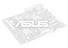
...Hyper-Threading Technology 1. Reboot the computer. To use the Hyper-Threading compliler to ensure system stability and performance. 3. This motherboard supports Intel Pentium 4 CPUs with a surface mount 478-pin Zero Insertion Force (ZIF) socket. Hyper-Threading Technology is ...micron process. If you installed a CPU that should match a specific corner of the CPU socket. ASUS P4GE-VM motherboard user guide 1-9 1.7 Central Processing Unit (CPU) 1.7.1 Overview The motherboard comes with Hyper-Threading Technology. 2. The socket is designed for the Intel® Pentium® ...
...Hyper-Threading Technology 1. Reboot the computer. To use the Hyper-Threading compliler to ensure system stability and performance. 3. This motherboard supports Intel Pentium 4 CPUs with a surface mount 478-pin Zero Insertion Force (ZIF) socket. Hyper-Threading Technology is ...micron process. If you installed a CPU that should match a specific corner of the CPU socket. ASUS P4GE-VM motherboard user guide 1-9 1.7 Central Processing Unit (CPU) 1.7.1 Overview The motherboard comes with Hyper-Threading Technology. 2. The socket is designed for the Intel® Pentium® ...

P4GE-VM user manual E1251
Page 20
...° angle, otherwise the CPU does not fit in place, push down the socket lever to the CPU_FAN1 connector on the motherboard. 2. Locate the 478-pin ZIF socket on the motherboard. 1-10 Chapter 1: Product introduction DO NOT force the CPU into the socket until it up to a 90°- 100° angle...
...° angle, otherwise the CPU does not fit in place, push down the socket lever to the CPU_FAN1 connector on the motherboard. 2. Locate the 478-pin ZIF socket on the motherboard. 1-10 Chapter 1: Product introduction DO NOT force the CPU into the socket until it up to a 90°- 100° angle...

P4GE-VM user manual E1251
Page 21
Unlock a DIMM socket by pressing the retaining clips outward. Unlocked Retaining Clip ASUS P4GE-VM motherboard user guide 1-11 Failure to do so may cause severe damage to unplug the power supply before adding or removing DIMMs or other system components. ... matches the break on the CPU FSB (Front Side Bus) and the type of the DDR DIMM sockets. ® 80 Pins P4GE-VM 104 Pins P4GE-VM 184-Pin DDR DIMM Sockets This motherboard supports different memory frequencies depending on the socket. 3. CPU FSB 533 MHz 400 MHz DDR DIMM Type PC2700 PC2100 PC2100 PC1600...
Unlock a DIMM socket by pressing the retaining clips outward. Unlocked Retaining Clip ASUS P4GE-VM motherboard user guide 1-11 Failure to do so may cause severe damage to unplug the power supply before adding or removing DIMMs or other system components. ... matches the break on the CPU FSB (Front Side Bus) and the type of the DDR DIMM sockets. ® 80 Pins P4GE-VM 104 Pins P4GE-VM 184-Pin DDR DIMM Sockets This motherboard supports different memory frequencies depending on the socket. 3. CPU FSB 533 MHz 400 MHz DDR DIMM Type PC2700 PC2100 PC2100 PC1600...
P4GE-VM user manual E1251
Page 22
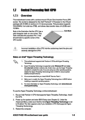
... to the tables below. 4. NOTE: The AGP slot supports only 1.5V AGP cards. 2. See Chapter 2 for this motherboard A B C D E F GH PCI slot 1 - - - - - Onboard USB 2.0 controller shared Onboard LAN (optional) - - - - used - - - - - Onboard USB controller 3 - - 1.9 Expansion slots The motherboard has three PCI slots and one Accelerated Graphics Port (AGP) slot. used - - - - - - Refer to the card...
... to the tables below. 4. NOTE: The AGP slot supports only 1.5V AGP cards. 2. See Chapter 2 for this motherboard A B C D E F GH PCI slot 1 - - - - - Onboard USB 2.0 controller shared Onboard LAN (optional) - - - - used - - - - - Onboard USB controller 3 - - 1.9 Expansion slots The motherboard has three PCI slots and one Accelerated Graphics Port (AGP) slot. used - - - - - - Refer to the card...

P4GE-VM user manual E1251
Page 23
... 38MHz 120MHz 60MHz 30MHz 125MHz 62MHz 31MHz 133MHz 66MHz 33MHz 135MHz 67MHz 33MHz Set the CPU frequency only to send the CPU. ASUS P4GE-VM motherboard user guide 1-13 If you are not guaranteed to pins 2-3 ( jumper mode) before setting the above switches. CPU external frequency...174; SW1 ON 12345 ON OFF P4GE-VM P4GE-VM DIP Switches 1.Frequency Selection 2.Frequency Selection 3.Frequency Selection 4.Frequency Selection 5.Frequency Selection Make sure that the J6 jumper is set to set to be stable. 1.10 Switches and jumpers The motherboard frequency is set the CPU core...
... 38MHz 120MHz 60MHz 30MHz 125MHz 62MHz 31MHz 133MHz 66MHz 33MHz 135MHz 67MHz 33MHz Set the CPU frequency only to send the CPU. ASUS P4GE-VM motherboard user guide 1-13 If you are not guaranteed to pins 2-3 ( jumper mode) before setting the above switches. CPU external frequency...174; SW1 ON 12345 ON OFF P4GE-VM P4GE-VM DIP Switches 1.Frequency Selection 2.Frequency Selection 3.Frequency Selection 4.Frequency Selection 5.Frequency Selection Make sure that the J6 jumper is set to set to be stable. 1.10 Switches and jumpers The motherboard frequency is set the CPU core...

P4GE-VM user manual E1251
Page 25
... up from S1 sleep mode (CPU stopped, DRAM refreshed, system running in sleep mode. ® P4GE-VM USBPWR_34 USBPWR_12 USBPWR_56 12 23 +5V (Default) +5VSB P4GE-VM USB Device Wake Up 5. SMBus 2.0 setting (6-pin J12) This jumper allows you to support this ...to pins 2-3 (Support), you can provide at least 1A on the motherboard. This feature requires a power supply that comply with SMBus 2.0 specification. ® P4GE-VM P4GE-VM SMBus 2.0 SMB2.0 2 1 Not Support (Default) 3 2 Support ASUS P4GE-VM motherboard user guide 1-15 When these jumpers are set to the front USB...
... up from S1 sleep mode (CPU stopped, DRAM refreshed, system running in sleep mode. ® P4GE-VM USBPWR_34 USBPWR_12 USBPWR_56 12 23 +5V (Default) +5VSB P4GE-VM USB Device Wake Up 5. SMBus 2.0 setting (6-pin J12) This jumper allows you to support this ...to pins 2-3 (Support), you can provide at least 1A on the motherboard. This feature requires a power supply that comply with SMBus 2.0 specification. ® P4GE-VM P4GE-VM SMBus 2.0 SMB2.0 2 1 Not Support (Default) 3 2 Support ASUS P4GE-VM motherboard user guide 1-15 When these jumpers are set to the front USB...
P4GE-VM user manual E1251
Page 26
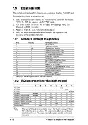
... the 6-channel audio software interface. ® BCS1 BCS2 12 23 P4GE-VM (BASS/CENTER) (CENTER/BASS) (Default) P4GE-VM Bass/Center Setting 1.11 Connectors This section describes and illustrates the internal connectors on the motherboard. 1. Hard disk activity LED (2-pin IDE_LED) This connector supplies power... to light up. ® P4GE-VM TIP: If the case-mounted LED does not light, try reversing the 2-pin plug. IDE_LED P4GE-VM HDD Activity LED 1-16 Chapter...
... the 6-channel audio software interface. ® BCS1 BCS2 12 23 P4GE-VM (BASS/CENTER) (CENTER/BASS) (Default) P4GE-VM Bass/Center Setting 1.11 Connectors This section describes and illustrates the internal connectors on the motherboard. 1. Hard disk activity LED (2-pin IDE_LED) This connector supplies power... to light up. ® P4GE-VM TIP: If the case-mounted LED does not light, try reversing the 2-pin plug. IDE_LED P4GE-VM HDD Activity LED 1-16 Chapter...

P4GE-VM user manual E1251
Page 27
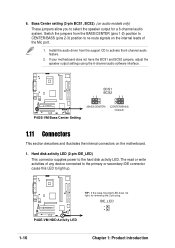
... its jumper accordingly. P4GE-VM PIN 1 P4GE-VM Floppy Disk Drive Connector 3. If you install two hard disks, you connect the cables. 2. Refer to the secondary IDE connector. It is removed to the UltraDMA/100/66 master device. one end to the motherboard, connect the other end to PIN 1. P4GE-VM PIN 1 P4GE-VM IDE Connectors ASUS P4GE-VM motherboard user guide 1-17...
... its jumper accordingly. P4GE-VM PIN 1 P4GE-VM Floppy Disk Drive Connector 3. If you install two hard disks, you connect the cables. 2. Refer to the secondary IDE connector. It is removed to the UltraDMA/100/66 master device. one end to the motherboard, connect the other end to PIN 1. P4GE-VM PIN 1 P4GE-VM IDE Connectors ASUS P4GE-VM motherboard user guide 1-17...

P4GE-VM user manual E1251
Page 28
...+12V power plug to provide sufficient power to an ATX 12V power supply. The plugs from the power supply are designed to this motherboard requires that your ATX 12V power supply can provide 8A on the +12V lead and at the back of the system chassis. In ... standby lead (+5VSB). The system may become unstable and may experience difficulty powering up if the power supply is purchased separately. ® COM2 PIN 1 P4GE-VM P4GE-VM Serial COM2 Bracket 5. ATX power connectors (20-pin ATX_POWER1, 4-pin ATX12V) These connectors connect to the CPU. Serial port 2 connector (10-1 pin ...
...+12V power plug to provide sufficient power to an ATX 12V power supply. The plugs from the power supply are designed to this motherboard requires that your ATX 12V power supply can provide 8A on the +12V lead and at the back of the system chassis. In ... standby lead (+5VSB). The system may become unstable and may experience difficulty powering up if the power supply is purchased separately. ® COM2 PIN 1 P4GE-VM P4GE-VM Serial COM2 Bracket 5. ATX power connectors (20-pin ATX_POWER1, 4-pin ATX12V) These connectors connect to the CPU. Serial port 2 connector (10-1 pin ...

P4GE-VM user manual E1251
Page 29
...cap from the pins. ® CHASSIS +5VSB_MB Chassis Signal GND P4GE-VM P4GE-VM Chassis Alarm Lead (Default) ASUS P4GE-VM motherboard user guide 1-19 Lack of 1A~2.22A (26.64W max.) at +12V. DO NOT place jumper caps on the motherboard, making sure that the black wire of each cable matches the... CHA_FAN1 GND +12V Rotation P4GE-VM 12-Volt Cooling Fan Power 7. 6. CPU and Chassis Fan Connectors (3-pin CPU_FAN1, CHA_FAN1) The fan connectors support cooling fans of 350mA~740mA (8.88W max.) or a total of sufficient air flow within the system may damage the motherboard components. By default, the...
...cap from the pins. ® CHASSIS +5VSB_MB Chassis Signal GND P4GE-VM P4GE-VM Chassis Alarm Lead (Default) ASUS P4GE-VM motherboard user guide 1-19 Lack of 1A~2.22A (26.64W max.) at +12V. DO NOT place jumper caps on the motherboard, making sure that the black wire of each cable matches the... CHA_FAN1 GND +12V Rotation P4GE-VM 12-Volt Cooling Fan Power 7. 6. CPU and Chassis Fan Connectors (3-pin CPU_FAN1, CHA_FAN1) The fan connectors support cooling fans of 350mA~740mA (8.88W max.) or a total of sufficient air flow within the system may damage the motherboard components. By default, the...


