P2B-S User Manual
Page 1
R P2B-L / P2B-S / P2B-LS Pentium® II Motherboards USER'S MANUAL Special Features ASUS P2B-L (power supply must provide at least 720mA on the +5VSB) • Intel 82558 LAN Chipset • Wake-On-LAN ASUS P2B-S • Adaptec 7890 SCSI Chipset • Adaptec 3860 SCSI Transceiver ASUS P2B-LS (power supply must provide at least 720mA on the +5VSB) • Intel 82558 LAN Chipset • Wake-On-LAN • Adaptec 7890 SCSI Chipset • Adaptec 3860 SCSI Transceiver
R P2B-L / P2B-S / P2B-LS Pentium® II Motherboards USER'S MANUAL Special Features ASUS P2B-L (power supply must provide at least 720mA on the +5VSB) • Intel 82558 LAN Chipset • Wake-On-LAN ASUS P2B-S • Adaptec 7890 SCSI Chipset • Adaptec 3860 SCSI Transceiver ASUS P2B-LS (power supply must provide at least 720mA on the +5VSB) • Intel 82558 LAN Chipset • Wake-On-LAN • Adaptec 7890 SCSI Chipset • Adaptec 3860 SCSI Transceiver

P2B-S User Manual
Page 2
... SB-LINK are trademarks of Creative Technology Ltd. • Adobe and Acrobat are both printed on the following page. Product Name: ASUS P2B-L/P2B-S/P2B-LS Manual Revision: 1.06 E265 Release Date: August 1998 2 ASUS P2B-L/P2B-S/P2B-LS User's Manual Product warranty or service will not be extended if: (1) the product is repaired, modified or altered, unless such repair, modification...
... SB-LINK are trademarks of Creative Technology Ltd. • Adobe and Acrobat are both printed on the following page. Product Name: ASUS P2B-L/P2B-S/P2B-LS Manual Revision: 1.06 E265 Release Date: August 1998 2 ASUS P2B-L/P2B-S/P2B-LS User's Manual Product warranty or service will not be extended if: (1) the product is repaired, modified or altered, unless such repair, modification...

P2B-S User Manual
Page 3
...-2-2894-3447 Fax: +886-2-2894-3449 Email: info@asus.com.tw Technical Support Fax: +886-2-2895-9254 BBS: +886-2-2896-4667 Email: tsd@asus.com.tw WWW: www.asus.com.tw FTP: ftp.asus.com.tw/pub/ASUS ASUS COMPUTER INTERNATIONAL Marketing Address: 6737 Mowry Avenue, Mowry Business...-445011 Fax: 49-2102-442066 Email: info-ger@asus.com.tw Technical Support Hotline: 49-2102-499712 BBS: 49-2102-448690 Email: tsd-ger@asus.com.tw WWW: www.asuscom.de FTP: ftp.asuscom.de/pub/ASUSCOM ASUS P2B-L/P2B-S/P2B-LS User's Manual 3 ASUS CONTACT INFORMATION ASUSTeK COMPUTER INC.
...-2-2894-3447 Fax: +886-2-2894-3449 Email: info@asus.com.tw Technical Support Fax: +886-2-2895-9254 BBS: +886-2-2896-4667 Email: tsd@asus.com.tw WWW: www.asus.com.tw FTP: ftp.asus.com.tw/pub/ASUS ASUS COMPUTER INTERNATIONAL Marketing Address: 6737 Mowry Avenue, Mowry Business...-445011 Fax: 49-2102-442066 Email: info-ger@asus.com.tw Technical Support Hotline: 49-2102-499712 BBS: 49-2102-448690 Email: tsd-ger@asus.com.tw WWW: www.asuscom.de FTP: ftp.asuscom.de/pub/ASUSCOM ASUS P2B-L/P2B-S/P2B-LS User's Manual 3 ASUS CONTACT INFORMATION ASUSTeK COMPUTER INC.
P2B-S User Manual
Page 4
CONTENTS I. Jumpers 12 Jumper Settings 13 2. External Connectors 26 Power Connection Procedures 35 IV. FEATURES Features 8 ASUS P2B-L/P2B-S/P2B-LS Motherboard 9 III. INSTALLATION ASUS P2B-L/P2B-S/P2B-LS Motherboard Layout 10 Installation Steps 12 1. Expansion Cards 24 Expansion Card Installation Procedure 24 Assigning IRQs for Expansion Cards 24 Assigning DMA Channels for ... of BIOS Features Setup 43 Chipset Features Setup 46 Details of Chipset Features Setup 46 Power Management Setup 49 Details of Power Management Setup 49 4 ASUS P2B-L/P2B-S/P2B-LS User's Manual
CONTENTS I. Jumpers 12 Jumper Settings 13 2. External Connectors 26 Power Connection Procedures 35 IV. FEATURES Features 8 ASUS P2B-L/P2B-S/P2B-LS Motherboard 9 III. INSTALLATION ASUS P2B-L/P2B-S/P2B-LS Motherboard Layout 10 Installation Steps 12 1. Expansion Cards 24 Expansion Card Installation Procedure 24 Assigning IRQs for Expansion Cards 24 Assigning DMA Channels for ... of BIOS Features Setup 43 Chipset Features Setup 46 Details of Chipset Features Setup 46 Power Management Setup 49 Details of Power Management Setup 49 4 ASUS P2B-L/P2B-S/P2B-LS User's Manual

P2B-S User Manual
Page 5
... VIII. CONTENTS PNP and PCI Setup 52 Details of PNP and PCI Setup 52 Load BIOS Defaults 54 Load Setup Defaults 54 Supervisor Password and User Password 55 IDE HDD Auto Detection 56 Save & Exit Setup 57 Exit Without Saving 57 V. Support CD Support CD Main Menu 58 Main Menu ...59 Other CD Directories 59 VI. NETWORK INTERFACE Features 63 Software Driver Support 63 LED Connectors 64 DOS and Windows 3.1 Setup for DOS/Windows 3.1x Users 83 DOS Formatting Utilities 84 Low-level Formatter (scsifmt 84 Formatter and Partitioner (afdisk 85 ASUS P2B-L/P2B-S/P2B-LS User's Manual 5
... VIII. CONTENTS PNP and PCI Setup 52 Details of PNP and PCI Setup 52 Load BIOS Defaults 54 Load Setup Defaults 54 Supervisor Password and User Password 55 IDE HDD Auto Detection 56 Save & Exit Setup 57 Exit Without Saving 57 V. Support CD Support CD Main Menu 58 Main Menu ...59 Other CD Directories 59 VI. NETWORK INTERFACE Features 63 Software Driver Support 63 LED Connectors 64 DOS and Windows 3.1 Setup for DOS/Windows 3.1x Users 83 DOS Formatting Utilities 84 Low-level Formatter (scsifmt 84 Formatter and Partitioner (afdisk 85 ASUS P2B-L/P2B-S/P2B-LS User's Manual 5

P2B-S User Manual
Page 6
... installation. Changes or modifications to the graphics card is connected. • Consult the dealer or an experienced radio/TV technician for connection of Communications. 6 ASUS P2B-L/P2B-S/P2B-LS User's Manual These limits are designed to comply with FCC regulations. The use of shielded cables for help. Operation is subject to the following measures: • Re...
... installation. Changes or modifications to the graphics card is connected. • Consult the dealer or an experienced radio/TV technician for connection of Communications. 6 ASUS P2B-L/P2B-S/P2B-LS User's Manual These limits are designed to comply with FCC regulations. The use of shielded cables for help. Operation is subject to the following measures: • Re...
P2B-S User Manual
Page 7
... cable for (1) 5.25inch floppy and (2) 3.5inch floppies (1) Spare jumpers (1) Support drivers and utilities (1) User's Manual 68-pin Ultra2 SCSI cable with terminator (optional) 68-pin Fast & Wide SCSI cable (optional) 50-pin Fast SCSI cable (optional) Network condition connector module (optional) ASUS P2B-L/P2B-S/P2B-LS User's Manual 7 INTRODUCTION How this Manual is Organized This manual is complete. BIOS Software V.
... cable for (1) 5.25inch floppy and (2) 3.5inch floppies (1) Spare jumpers (1) Support drivers and utilities (1) User's Manual 68-pin Ultra2 SCSI cable with terminator (optional) 68-pin Fast & Wide SCSI cable (optional) 50-pin Fast SCSI cable (optional) Network condition connector module (optional) ASUS P2B-L/P2B-S/P2B-LS User's Manual 7 INTRODUCTION How this Manual is Organized This manual is complete. BIOS Software V.
P2B-S User Manual
Page 8
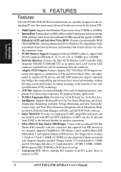
...floppy disk drives (3.5-inch disk drive: 120 MB, 1.44MB, 720KB). UART2 can also be directed from COM2 to CPU. 8 ASUS P2B-L/P2B-S/P2B-LS User's Manual Two floppy drives of either 5.25inch or 3.5inch (1.44MB or 2.88MB) are carefully designed for high performance, component level interconnect targeted.../33, PIO Modes 3 and 4 and Bus Master IDE DMA Mode 2, and supports Enhanced IDE devices. FEATURES Features The ASUS P2B-L/P2B-S/P2B-LS motherboards are also supported without affecting system performance by taking advantage of the benefits of most devices for virtually automatic setup....
...floppy disk drives (3.5-inch disk drive: 120 MB, 1.44MB, 720KB). UART2 can also be directed from COM2 to CPU. 8 ASUS P2B-L/P2B-S/P2B-LS User's Manual Two floppy drives of either 5.25inch or 3.5inch (1.44MB or 2.88MB) are carefully designed for high performance, component level interconnect targeted.../33, PIO Modes 3 and 4 and Bus Master IDE DMA Mode 2, and supports Enhanced IDE devices. FEATURES Features The ASUS P2B-L/P2B-S/P2B-LS motherboards are also supported without affecting system performance by taking advantage of the benefits of most devices for virtually automatic setup....
P2B-S User Manual
Page 9
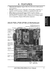
FEATURES Motherboard Parts ASUS P2B-L/P2B-S/P2B-LS Motherboard SEC CPU Slot T: PS/2 Mouse B: PS/2 Keyboard T: USB Port 1 B: USB Port 2 COM 1 (Bottom) Parallel (Top) Serial (Bottom) COM 2 (Bottom) Intel 440BX AGPset...7890 Ultra2 & Ultra-Fast/ Wide SCSI Chipset (optional) Accelerated Graphics Port 4PCI Slots Multi-I/O Hardware Monitor 2 ISA Slots Intel PIIX4E Programmable PCIset 2Mbit Flash ROM ASUS P2B-L/P2B-S/P2B-LS User's Manual 9 FEATURES • Wake-On-LAN Connector: Supports Wake-On-LAN activity with the optional network interface. • SB-Link™: Features Creative's SB-...
FEATURES Motherboard Parts ASUS P2B-L/P2B-S/P2B-LS Motherboard SEC CPU Slot T: PS/2 Mouse B: PS/2 Keyboard T: USB Port 1 B: USB Port 2 COM 1 (Bottom) Parallel (Top) Serial (Bottom) COM 2 (Bottom) Intel 440BX AGPset...7890 Ultra2 & Ultra-Fast/ Wide SCSI Chipset (optional) Accelerated Graphics Port 4PCI Slots Multi-I/O Hardware Monitor 2 ISA Slots Intel PIIX4E Programmable PCIset 2Mbit Flash ROM ASUS P2B-L/P2B-S/P2B-LS User's Manual 9 FEATURES • Wake-On-LAN Connector: Supports Wake-On-LAN activity with the optional network interface. • SB-Link™: Features Creative's SB-...

P2B-S User Manual
Page 10
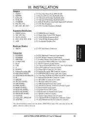
III. III. INSTALLATION ASUS P2B-L/P2B-S/P2B-LS Motherboard Layout DIMM Socket 0 (64/72 bit, 168 pin ...(bottom port) USB KBPWR COM 1 TRCPU CPU_FAN Intel 440BX AGPset FS2 FS1 BUS Freq. INSTALLATION Board Layout 10 ASUS P2B-L/P2B-S/P2B-LS User's Manual FS0 68 34 34 68 COM 2 RJ-45 FLOPPY LAN Activity LED Connector 35 1 35 1 50-Pin ... SCSI Chipset Adaptec AIC-3860 Chipset SECONDARY IDE 1 PRIMARY IDE Intel PIIX4E Chipset CLRTC 1 Freq. Ratio ASUS A97127F Chipset BF3 BF2 BF1 BF0 BIOS Power (CR2032 3V Lithium Cell) SCSILED CHASSIS WOL_CON EXTBATT 2Mbit Flash...
III. III. INSTALLATION ASUS P2B-L/P2B-S/P2B-LS Motherboard Layout DIMM Socket 0 (64/72 bit, 168 pin ...(bottom port) USB KBPWR COM 1 TRCPU CPU_FAN Intel 440BX AGPset FS2 FS1 BUS Freq. INSTALLATION Board Layout 10 ASUS P2B-L/P2B-S/P2B-LS User's Manual FS0 68 34 34 68 COM 2 RJ-45 FLOPPY LAN Activity LED Connector 35 1 35 1 50-Pin ... SCSI Chipset Adaptec AIC-3860 Chipset SECONDARY IDE 1 PRIMARY IDE Intel PIIX4E Chipset CLRTC 1 Freq. Ratio ASUS A97127F Chipset BF3 BF2 BF1 BF0 BIOS Power (CR2032 3V Lithium Cell) SCSILED CHASSIS WOL_CON EXTBATT 2Mbit Flash...
P2B-S User Manual
Page 11
... Connector (20 pins) *The onboard hardware monitor uses the address 290H-297H so legacy ISA cards must not use this address, otherwise conflicts will occur. ASUS P2B-L/P2B-S/P2B-LS User's Manual 11
... Connector (20 pins) *The onboard hardware monitor uses the address 290H-297H so legacy ISA cards must not use this address, otherwise conflicts will occur. ASUS P2B-L/P2B-S/P2B-LS User's Manual 11
P2B-S User Manual
Page 12
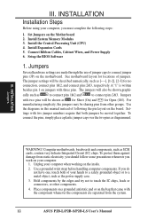
...some precautions whenever you work on jumpers with two jumper numbers require that came with two pins will be sharing pins from the system. 12 ASUS P2B-L/P2B-S/P2B-LS User's Manual Hold components by the edges and try not to a metal object, such as for Short (On) and for no connection, connect pins ... pins as SCSI cards, contain very delicate Integrated Circuit (IC) chips. cally such as [----], [1-2], [2-3] for Open (Off). Use the diagrams in this manual instead of jumper caps to connect pins 2&3. III. Set Jumpers on the motherboard. Install System Memory Modules 3.
...some precautions whenever you work on jumpers with two jumper numbers require that came with two pins will be sharing pins from the system. 12 ASUS P2B-L/P2B-S/P2B-LS User's Manual Hold components by the edges and try not to a metal object, such as for Short (On) and for no connection, connect pins ... pins as SCSI cards, contain very delicate Integrated Circuit (IC) chips. cally such as [----], [1-2], [2-3] for Open (Off). Use the diagrams in this manual instead of jumper caps to connect pins 2&3. III. Set Jumpers on the motherboard. Install System Memory Modules 3.

P2B-S User Manual
Page 13
... III. Set to Enable if you to use your computer, (4) Hold down during bootup and enter BIOS setup to clear CMOS R CLRTC P2B-L/S/LS Real Time Clock RAM (CLRTC) 2. INSTALLATION Jumper Settings 1. Keyboard Power Up (KBPWR) This allows you want to disable or enable the...(3) Turn on the +5VSB lead and the new ACPI BIOS support. KBPWR 123 Disable (Default) KBPWR 123 Enable R P2B-L/S/LS Keyboard Power (Wake) Up ASUS P2B-L/P2B-S/P2B-LS User's Manual 13 The default is powered by pressing ) to Disable because not all computers have the right ATX power supply. Clear ...
... III. Set to Enable if you to use your computer, (4) Hold down during bootup and enter BIOS setup to clear CMOS R CLRTC P2B-L/S/LS Real Time Clock RAM (CLRTC) 2. INSTALLATION Jumper Settings 1. Keyboard Power Up (KBPWR) This allows you want to disable or enable the...(3) Turn on the +5VSB lead and the new ACPI BIOS support. KBPWR 123 Disable (Default) KBPWR 123 Enable R P2B-L/S/LS Keyboard Power (Wake) Up ASUS P2B-L/P2B-S/P2B-LS User's Manual 13 The default is powered by pressing ) to Disable because not all computers have the right ATX power supply. Clear ...
P2B-S User Manual
Page 14
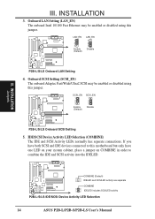
... using this jumper. COMBINE (Default) IDELED and SCSILED activity are separate COMBINE IDELED includes SCSILED activity P2B-L/S/LS IDE/SCSI Device Activity LED Selection 14 ASUS P2B-L/P2B-S/P2B-LS User's Manual If you have one LED on your system cabinet, place a jumper on COMBINE in order to this... connected to combine the IDE and SCSI activity into the IDELED. LAN_EN 1 2 3 Enable (Default) LAN_EN 1 2 3 Disable P2B-L/S/LS Onboard LAN Setting 4. SCSI_EN 1 2 3 Enable (Default) SCSI_EN 1 2 3 Disable P2B-L/S/LS Onboard SCSI Setting 5. R R R III. INSTALLATION Jumpers III.
... using this jumper. COMBINE (Default) IDELED and SCSILED activity are separate COMBINE IDELED includes SCSILED activity P2B-L/S/LS IDE/SCSI Device Activity LED Selection 14 ASUS P2B-L/P2B-S/P2B-LS User's Manual If you have one LED on your system cabinet, place a jumper on COMBINE in order to this... connected to combine the IDE and SCSI activity into the IDELED. LAN_EN 1 2 3 Enable (Default) LAN_EN 1 2 3 Disable P2B-L/S/LS Onboard LAN Setting 4. SCSI_EN 1 2 3 Enable (Default) SCSI_EN 1 2 3 Disable P2B-L/S/LS Onboard SCSI Setting 5. R R R III. INSTALLATION Jumpers III.

P2B-S User Manual
Page 15
...100MHz 100MHz 66MHz 66MHz 66MHz 66MHz (BUS Freq.) FS2 FS1 FS0 [1-2] [1-2] [1-2] [1-2] [1-2] [1-2] [1-2] [1-2] [1-2] [2-3] [1-2] [1-2] [2-3] [1-2] [1-2] [2-3] [1-2] [1-2] [2-3] [1-2] [1-2] (Freq. R P2B-L/S/LS CPU Settings 123 123 123 123 123 123 123 123 123 BF3 BF2 BF1 BF0 2.0x (2/1) 2.5x (5/2) 3.0x (3/1) 3.5x (7/2) 4.0x (4/1) 4.5x (9/2) 5.0x (5/1) 5.5x (...Set the jumpers by the BUS Ratio equals the CPU's Internal frequency (the advertised CPU speed). 7. ASUS P2B-L/P2B-S/P2B-LS User's Manual 15 CPU Bus Frequency (FS0, FS1, FS2) This option tells the clock generator what frequency to ...
...100MHz 100MHz 66MHz 66MHz 66MHz 66MHz (BUS Freq.) FS2 FS1 FS0 [1-2] [1-2] [1-2] [1-2] [1-2] [1-2] [1-2] [1-2] [1-2] [2-3] [1-2] [1-2] [2-3] [1-2] [1-2] [2-3] [1-2] [1-2] [2-3] [1-2] [1-2] (Freq. R P2B-L/S/LS CPU Settings 123 123 123 123 123 123 123 123 123 BF3 BF2 BF1 BF0 2.0x (2/1) 2.5x (5/2) 3.0x (3/1) 3.5x (7/2) 4.0x (4/1) 4.5x (9/2) 5.0x (5/1) 5.5x (...Set the jumpers by the BUS Ratio equals the CPU's Internal frequency (the advertised CPU speed). 7. ASUS P2B-L/P2B-S/P2B-LS User's Manual 15 CPU Bus Frequency (FS0, FS1, FS2) This option tells the clock generator what frequency to ...

P2B-S User Manual
Page 16
(This page was intentionally left blank.) 16 ASUS P2B-L/P2B-S/P2B-LS User's Manual
(This page was intentionally left blank.) 16 ASUS P2B-L/P2B-S/P2B-LS User's Manual

P2B-S User Manual
Page 17
...16, 32, 64, 128, 256MB x1 Socket 4 (Rows 6&7) SDRAM 8, 16, 32, 64, 128, 256MB x1 Total System Memory (Max 1024MB) = ASUS Memory Module Example: III. INSTALLATION System Memory SDRAM DIMM (8 chips, Non-ECC) General DIMM Notes • Use only PC100-compliant DIMMs. This motherboard operates ..., 64,128MB and double-sided DIMMs come in 32, 64, 128, 256MB sizes. Install memory in IV. BIOS SOFTWARE. ASUS P2B-L/P2B-S/P2B-LS User's Manual 17 INSTALLATION 2. System Memory (DIMM) This motherboard uses only Dual Inline Memory Modules (DIMMs). One side (with the current Intel PC100...
...16, 32, 64, 128, 256MB x1 Socket 4 (Rows 6&7) SDRAM 8, 16, 32, 64, 128, 256MB x1 Total System Memory (Max 1024MB) = ASUS Memory Module Example: III. INSTALLATION System Memory SDRAM DIMM (8 chips, Non-ECC) General DIMM Notes • Use only PC100-compliant DIMMs. This motherboard operates ..., 64,128MB and double-sided DIMMs come in 32, 64, 128, 256MB sizes. Install memory in IV. BIOS SOFTWARE. ASUS P2B-L/P2B-S/P2B-LS User's Manual 17 INSTALLATION 2. System Memory (DIMM) This motherboard uses only Dual Inline Memory Modules (DIMMs). One side (with the current Intel PC100...
P2B-S User Manual
Page 18
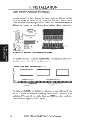
DRAM SIMM modules have a higher pin density. 20 Pins 60 Pins 88 Pins Lock (FRONT) P2B-L/S/LS 168-Pin DIMM Memory Sockets The DIMMs must tell your retailer the correct DIMM type before purchasing. SDRAM DIMMs have different pin contacts on ... type and also to prevent the wrong type from being inserted into the DIMM slot on both sides. This motherboard supports four clock signals. 18 ASUS P2B-L/P2B-S/P2B-LS User's Manual INSTALLATION DIMM Memory Installation Procedures: Insert the module(s) as shown.
DRAM SIMM modules have a higher pin density. 20 Pins 60 Pins 88 Pins Lock (FRONT) P2B-L/S/LS 168-Pin DIMM Memory Sockets The DIMMs must tell your retailer the correct DIMM type before purchasing. SDRAM DIMMs have different pin contacts on ... type and also to prevent the wrong type from being inserted into the DIMM slot on both sides. This motherboard supports four clock signals. 18 ASUS P2B-L/P2B-S/P2B-LS User's Manual INSTALLATION DIMM Memory Installation Procedures: Insert the module(s) as shown.
P2B-S User Manual
Page 19
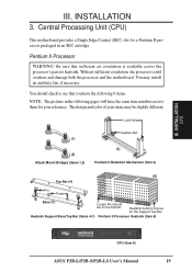
... motherboard provides a Single Edge Contact (SEC) slot for the Support Top Bar Heatsink Support Base/Top Bar (Items 4-7) Pentium II Processor Heatsink (Item 8) CPU (Item 9) ASUS P2B-L/P2B-S/P2B-LS User's Manual 19 Pentium II Processor WARNING!
... motherboard provides a Single Edge Contact (SEC) slot for the Support Top Bar Heatsink Support Base/Top Bar (Items 4-7) Pentium II Processor Heatsink (Item 8) CPU (Item 9) ASUS P2B-L/P2B-S/P2B-LS User's Manual 19 Pentium II Processor WARNING!
P2B-S User Manual
Page 20
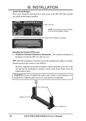
... that the mechanism is designed to no more than 6±1 inch/pound. Do not overtighten the captive nuts. Lock holes Captive nut Captive nut 20 ASUS P2B-L/P2B-S/P2B-LS User's Manual SEC CPU slot NOTE: Encircled items are the screws from the mount bridges (1 & 2) Attach Mount Bridges (underside) III. Be sure to each corner of...
... that the mechanism is designed to no more than 6±1 inch/pound. Do not overtighten the captive nuts. Lock holes Captive nut Captive nut 20 ASUS P2B-L/P2B-S/P2B-LS User's Manual SEC CPU slot NOTE: Encircled items are the screws from the mount bridges (1 & 2) Attach Mount Bridges (underside) III. Be sure to each corner of...

