P2B-S User Manual
Page 1
R P2B-L / P2B-S / P2B-LS Pentium® II Motherboards USER'S MANUAL Special Features ASUS P2B-L (power supply must provide at least 720mA on the +5VSB) • Intel 82558 LAN Chipset • Wake-On-LAN ASUS P2B-S • Adaptec 7890 SCSI Chipset • Adaptec 3860 SCSI Transceiver ASUS P2B-LS (power supply must provide at least 720mA on the +5VSB) • Intel 82558 LAN Chipset • Wake-On-LAN • Adaptec 7890 SCSI Chipset • Adaptec 3860 SCSI Transceiver
R P2B-L / P2B-S / P2B-LS Pentium® II Motherboards USER'S MANUAL Special Features ASUS P2B-L (power supply must provide at least 720mA on the +5VSB) • Intel 82558 LAN Chipset • Wake-On-LAN ASUS P2B-S • Adaptec 7890 SCSI Chipset • Adaptec 3860 SCSI Transceiver ASUS P2B-LS (power supply must provide at least 720mA on the +5VSB) • Intel 82558 LAN Chipset • Wake-On-LAN • Adaptec 7890 SCSI Chipset • Adaptec 3860 SCSI Transceiver
P2B-S User Manual
Page 4
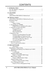
External Connectors 26 Power Connection Procedures 35 IV. INSTALLATION ASUS P2B-L/P2B-S/P2B-LS Motherboard Layout 10 Installation Steps 12 1. Jumpers 12 Jumper Settings 13 2. BIOS Setup 39 Load Defaults 40 Standard ...Details of Power Management Setup 49 4 ASUS P2B-L/P2B-S/P2B-LS User's Manual BIOS SOFTWARE Main Menu 36 Flash Memory Writer Utility 36 Managing and Updating Your Motherboard's BIOS 38 6. System Memory (DIMM 17 DIMM Memory Installation Procedures 18 3. FEATURES Features 8 ASUS P2B-L/P2B-S/P2B-LS Motherboard 9 III. Expansion Cards 24 Expansion Card...
External Connectors 26 Power Connection Procedures 35 IV. INSTALLATION ASUS P2B-L/P2B-S/P2B-LS Motherboard Layout 10 Installation Steps 12 1. Jumpers 12 Jumper Settings 13 2. BIOS Setup 39 Load Defaults 40 Standard ...Details of Power Management Setup 49 4 ASUS P2B-L/P2B-S/P2B-LS User's Manual BIOS SOFTWARE Main Menu 36 Flash Memory Writer Utility 36 Managing and Updating Your Motherboard's BIOS 38 6. System Memory (DIMM 17 DIMM Memory Installation Procedures 18 3. FEATURES Features 8 ASUS P2B-L/P2B-S/P2B-LS Motherboard 9 III. Expansion Cards 24 Expansion Card...
P2B-S User Manual
Page 7
... controller (optional) Adaptec SCSI Select utility (optional) Adaptec EZ-SCSI utility (optional) Item Checklist Check that your retailer. (1) ASUS Motherboard (1) Retention mechanism & heatsink support for CPU and heatsink (2) Attach mount bridges (1) IDE ribbon cable for master and slave drives...) 50-pin Fast SCSI cable (optional) Network condition connector module (optional) ASUS P2B-L/P2B-S/P2B-LS User's Manual 7 DMI Utility VII. Instructions on setting up the BIOS software ASUS Smart Motherboard Support CD BIOS supported Desktop Management Interface Information on setting up the...
... controller (optional) Adaptec SCSI Select utility (optional) Adaptec EZ-SCSI utility (optional) Item Checklist Check that your retailer. (1) ASUS Motherboard (1) Retention mechanism & heatsink support for CPU and heatsink (2) Attach mount bridges (1) IDE ribbon cable for master and slave drives...) 50-pin Fast SCSI cable (optional) Network condition connector module (optional) ASUS P2B-L/P2B-S/P2B-LS User's Manual 7 DMI Utility VII. Instructions on setting up the BIOS software ASUS Smart Motherboard Support CD BIOS supported Desktop Management Interface Information on setting up the...
P2B-S User Manual
Page 8
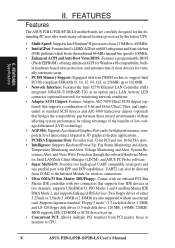
FEATURES Features The ASUS P2B-L/P2B-S/P2B-LS motherboards are also supported without affecting system performance by taking advantage of ... MB, 1.44MB, 720KB). UART2 can also be directed from PCI master buses to memory to CPU. 8 ASUS P2B-L/P2B-S/P2B-LS User's Manual BIOS supports IDE CD-ROM or SCSI device boot-up. • Concurrent PCI: Allows ... System Resources Alert, and Virus Write Protection through the onboard Hardware Monitor, Intel LANDesk Client Manager (LDCM), and ASUS PC Probe software. • Super Multi-I /O subsystems and front-side bus (FSB) platform, which boosts the ...
FEATURES Features The ASUS P2B-L/P2B-S/P2B-LS motherboards are also supported without affecting system performance by taking advantage of ... MB, 1.44MB, 720KB). UART2 can also be directed from PCI master buses to memory to CPU. 8 ASUS P2B-L/P2B-S/P2B-LS User's Manual BIOS supports IDE CD-ROM or SCSI device boot-up. • Concurrent PCI: Allows ... System Resources Alert, and Virus Write Protection through the onboard Hardware Monitor, Intel LANDesk Client Manager (LDCM), and ASUS PC Probe software. • Super Multi-I /O subsystems and front-side bus (FSB) platform, which boosts the ...
P2B-S User Manual
Page 9
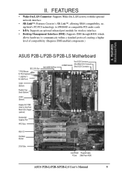
... (DMI): Supports DMI through BIOS, which allows hardware to communicate within a standard protocol creating a higher level of compatibility. (Requires DMI-enabled components.) II. FEATURES Motherboard Parts ASUS P2B-L/P2B-S/P2B-LS Motherboard SEC CPU Slot T: PS/2 Mouse B: PS/2 Keyboard T: USB Port 1 B: USB Port 2 COM 1 (Bottom) Parallel (Top) Serial (Bottom) COM 2 (Bottom) Intel ...-Fast/ Wide SCSI Chipset (optional) Accelerated Graphics Port 4PCI Slots Multi-I/O Hardware Monitor 2 ISA Slots Intel PIIX4E Programmable PCIset 2Mbit Flash ROM ASUS P2B-L/P2B-S/P2B-LS User's Manual 9 II.
... (DMI): Supports DMI through BIOS, which allows hardware to communicate within a standard protocol creating a higher level of compatibility. (Requires DMI-enabled components.) II. FEATURES Motherboard Parts ASUS P2B-L/P2B-S/P2B-LS Motherboard SEC CPU Slot T: PS/2 Mouse B: PS/2 Keyboard T: USB Port 1 B: USB Port 2 COM 1 (Bottom) Parallel (Top) Serial (Bottom) COM 2 (Bottom) Intel ...-Fast/ Wide SCSI Chipset (optional) Accelerated Graphics Port 4PCI Slots Multi-I/O Hardware Monitor 2 ISA Slots Intel PIIX4E Programmable PCIset 2Mbit Flash ROM ASUS P2B-L/P2B-S/P2B-LS User's Manual 9 II.

P2B-S User Manual
Page 10
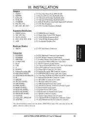
III. INSTALLATION Board Layout 10 ASUS P2B-L/P2B-S/P2B-LS User's Manual III. FS0 68 34 34 68 COM 2 RJ-45 FLOPPY LAN Activity LED Connector 35 1 35 1 50-Pin SCSI 1 1 68-Pin Wide ... CHASSIS WOL_CON EXTBATT 2Mbit Flash EEPROM (Programmable BIOS) CHA_FAN PANEL IDELED Combine IR Speaker NOTE: Greyed components are optional at the time of purchase. INSTALLATION ASUS P2B-L/P2B-S/P2B-LS Motherboard Layout DIMM Socket 0 (64/72 bit, 168 pin module) DIMM Socket 1 (64/72 bit, 168 pin module) DIMM Socket 2 (64/72 bit, 168 pin...
III. INSTALLATION Board Layout 10 ASUS P2B-L/P2B-S/P2B-LS User's Manual III. FS0 68 34 34 68 COM 2 RJ-45 FLOPPY LAN Activity LED Connector 35 1 35 1 50-Pin SCSI 1 1 68-Pin Wide ... CHASSIS WOL_CON EXTBATT 2Mbit Flash EEPROM (Programmable BIOS) CHA_FAN PANEL IDELED Combine IR Speaker NOTE: Greyed components are optional at the time of purchase. INSTALLATION ASUS P2B-L/P2B-S/P2B-LS Motherboard Layout DIMM Socket 0 (64/72 bit, 168 pin module) DIMM Socket 1 (64/72 bit, 168 pin module) DIMM Socket 2 (64/72 bit, 168 pin...
P2B-S User Manual
Page 11
INSTALLATION Board Layout III. ASUS P2B-L/P2B-S/P2B-LS User's Manual 11 INSTALLATION Jumpers 1) CLRTC 2) KBPWR 3) LAN_EN 4) SCSI_EN 5) COMBINE 6) FS0, FS1, FS2 7) BF0, BF1, BF2, BF3 p. 13 Clear Real Time Clock (RTC) RAM p. ... (4 pins) 21) CHASSIS p. 33 Chassis Open Alarm Lead (4-1 pins) 22) CHA_/CPU_/PWR_FAN p. 33 Chassis/CPU/Power Supply Fan Connectors (3 pins) 23) ATXPWR p. 34 ATX Motherboard Power Connector (20 pins) *The onboard hardware monitor uses the address 290H-297H so legacy ISA cards must not use this address, otherwise conflicts will...
INSTALLATION Board Layout III. ASUS P2B-L/P2B-S/P2B-LS User's Manual 11 INSTALLATION Jumpers 1) CLRTC 2) KBPWR 3) LAN_EN 4) SCSI_EN 5) COMBINE 6) FS0, FS1, FS2 7) BF0, BF1, BF2, BF3 p. 13 Clear Real Time Clock (RTC) RAM p. ... (4 pins) 21) CHASSIS p. 33 Chassis Open Alarm Lead (4-1 pins) 22) CHA_/CPU_/PWR_FAN p. 33 Chassis/CPU/Power Supply Fan Connectors (3 pins) 23) ATXPWR p. 34 ATX Motherboard Power Connector (20 pins) *The onboard hardware monitor uses the address 290H-297H so legacy ISA cards must not use this address, otherwise conflicts will...
P2B-S User Manual
Page 12
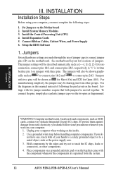
...be described numerically, such as for Short (On) and for no connection, connect pins 1&2, and connect pins 2&3, respectively. Computer motherboards, baseboards and components, such as to connect pins 1&2 and to connect pins 2&3. Jumpers Several hardware settings are separated from other components... very delicate Integrated Circuit (IC) chips. Jumpers with two pins will also be sharing pins from the system. 12 ASUS P2B-L/P2B-S/P2B-LS User's Manual For manufacturing simplicity, the jumpers may be shown graphi- To protect them against damage from static electricity...
...be described numerically, such as for Short (On) and for no connection, connect pins 1&2, and connect pins 2&3, respectively. Computer motherboards, baseboards and components, such as to connect pins 1&2 and to connect pins 2&3. Jumpers Several hardware settings are separated from other components... very delicate Integrated Circuit (IC) chips. Jumpers with two pins will also be sharing pins from the system. 12 ASUS P2B-L/P2B-S/P2B-LS User's Manual For manufacturing simplicity, the jumpers may be shown graphi- To protect them against damage from static electricity...
P2B-S User Manual
Page 14
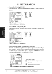
... in order to this jumper. R R R III. Onboard LAN Setting (LAN_EN) The onboard Intel 10/100 Fast Ethernet may be enabled or disabled using this motherboard but only have both SCSI and IDE devices connected to combine the IDE and SCSI activity into the IDELED. IDE/SCSI Device Activity LED Selection...COMBINE) The IDE and SCSI Activity LEDs normally has separate connections. INSTALLATION 3. COMBINE (Default) IDELED and SCSILED activity are separate COMBINE IDELED includes SCSILED activity P2B-L/S/LS IDE/SCSI Device Activity LED Selection 14 ASUS P2B-L/P2B-S/P2B-LS User's Manual
... in order to this jumper. R R R III. Onboard LAN Setting (LAN_EN) The onboard Intel 10/100 Fast Ethernet may be enabled or disabled using this motherboard but only have both SCSI and IDE devices connected to combine the IDE and SCSI activity into the IDELED. IDE/SCSI Device Activity LED Selection...COMBINE) The IDE and SCSI Activity LEDs normally has separate connections. INSTALLATION 3. COMBINE (Default) IDELED and SCSILED activity are separate COMBINE IDELED includes SCSILED activity P2B-L/S/LS IDE/SCSI Device Activity LED Selection 14 ASUS P2B-L/P2B-S/P2B-LS User's Manual

P2B-S User Manual
Page 17
... 32, 64, 128, 256MB x1 Total System Memory (Max 1024MB) = ASUS Memory Module Example: III. INSTALLATION System Memory SDRAM DIMM (8 chips, Non-ECC) General DIMM Notes • Use only PC100-compliant DIMMs. This motherboard operates at 100MHz, thus most systems will not even boot if non-compliant modules...side (with higher pin density than traditional EDO (Extended Data Output) chips. • BIOS shows SDRAM memory on the motherboard. ASUS P2B-L/P2B-S/P2B-LS User's Manual 17 System Memory (DIMM) This motherboard uses only Dual Inline Memory Modules (DIMMs). INSTALLATION 2.
... 32, 64, 128, 256MB x1 Total System Memory (Max 1024MB) = ASUS Memory Module Example: III. INSTALLATION System Memory SDRAM DIMM (8 chips, Non-ECC) General DIMM Notes • Use only PC100-compliant DIMMs. This motherboard operates at 100MHz, thus most systems will not even boot if non-compliant modules...side (with higher pin density than traditional EDO (Extended Data Output) chips. • BIOS shows SDRAM memory on the motherboard. ASUS P2B-L/P2B-S/P2B-LS User's Manual 17 System Memory (DIMM) This motherboard uses only Dual Inline Memory Modules (DIMMs). INSTALLATION 2.
P2B-S User Manual
Page 18
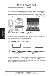
...have different pin contacts on both sides. INSTALLATION DIMM Memory Installation Procedures: Insert the module(s) as shown. This motherboard supports four clock signals. 18 ASUS P2B-L/P2B-S/P2B-LS User's Manual INSTALLATION System Memory III. R III. Because the number of pins are different on either side... RFU Unbuffered Buffered Voltage Key Position 5.0V Reserved 3.3V The notches on the motherboard. SDRAM DIMMs have a higher pin density. 20 Pins 60 Pins 88 Pins Lock (FRONT) P2B-L/S/LS 168-Pin DIMM Memory Sockets The DIMMs must tell your retailer the correct ...
...have different pin contacts on both sides. INSTALLATION DIMM Memory Installation Procedures: Insert the module(s) as shown. This motherboard supports four clock signals. 18 ASUS P2B-L/P2B-S/P2B-LS User's Manual INSTALLATION System Memory III. R III. Because the number of pins are different on either side... RFU Unbuffered Buffered Voltage Key Position 5.0V Reserved 3.3V The notches on the motherboard. SDRAM DIMMs have a higher pin density. 20 Pins 60 Pins 88 Pins Lock (FRONT) P2B-L/S/LS 168-Pin DIMM Memory Sockets The DIMMs must tell your retailer the correct ...
P2B-S User Manual
Page 19
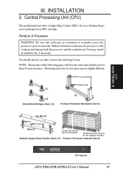
...the Support Top Bar Heatsink Support Base/Top Bar (Items 4-7) Pentium II Processor Heatsink (Item 8) CPU (Item 9) ASUS P2B-L/P2B-S/P2B-LS User's Manual 19 Heatsink bottom Groove for your items may install an auxiliary fan, if necessary. INSTALLATION 3. Without... sufficient circulation, the processor could overheat and damage both the processor and the motherboard. III. You should be slightly different. Lock Holes (1) (2) Attach Mount Bridges (Items 1,2) Captive Nut (3) Pentium II Retention Mechanism (...
...the Support Top Bar Heatsink Support Base/Top Bar (Items 4-7) Pentium II Processor Heatsink (Item 8) CPU (Item 9) ASUS P2B-L/P2B-S/P2B-LS User's Manual 19 Heatsink bottom Groove for your items may install an auxiliary fan, if necessary. INSTALLATION 3. Without... sufficient circulation, the processor could overheat and damage both the processor and the motherboard. III. You should be slightly different. Lock Holes (1) (2) Attach Mount Bridges (Items 1,2) Captive Nut (3) Pentium II Retention Mechanism (...
P2B-S User Manual
Page 20
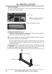
... the captive nuts in the mechanism with the two attach mount bridges installed. TIP: Orient the mechanism's lock holes toward the motherboard's chipset (see motherboard layout for the location of the SEC CPU Slot with the small rib on the board. WARNING! INSTALLATION Attach Mount Bridges Four...side of the slot and that the mechanism is designed to no more than 6±1 inch/pound. Lock holes Captive nut Captive nut 20 ASUS P2B-L/P2B-S/P2B-LS User's Manual SEC CPU slot NOTE: Encircled items are the screws from the mount bridges (1 & 2) Attach Mount Bridges (underside) III...
... the captive nuts in the mechanism with the two attach mount bridges installed. TIP: Orient the mechanism's lock holes toward the motherboard's chipset (see motherboard layout for the location of the SEC CPU Slot with the small rib on the board. WARNING! INSTALLATION Attach Mount Bridges Four...side of the slot and that the mechanism is designed to no more than 6±1 inch/pound. Lock holes Captive nut Captive nut 20 ASUS P2B-L/P2B-S/P2B-LS User's Manual SEC CPU slot NOTE: Encircled items are the screws from the mount bridges (1 & 2) Attach Mount Bridges (underside) III...
P2B-S User Manual
Page 21
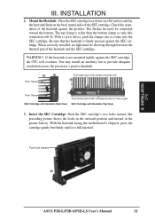
... heatsink. (8) (9) Push Clamp Push each end of the heatsink and the SEC cartridge. WARNING! Push lock inward (3) ASUS P2B-L/P2B-S/P2B-LS User's Manual 21 Check the orientation of the SEC cartridge. With the heatsink facing the motherboard's chipsets, press the cartridge gently but firmly until they lock (8) Lock Lock Push Clamp (9) The thermal pad...
... heatsink. (8) (9) Push Clamp Push each end of the heatsink and the SEC cartridge. WARNING! Push lock inward (3) ASUS P2B-L/P2B-S/P2B-LS User's Manual 21 Check the orientation of the SEC cartridge. With the heatsink facing the motherboard's chipsets, press the cartridge gently but firmly until they lock (8) Lock Lock Push Clamp (9) The thermal pad...
P2B-S User Manual
Page 22
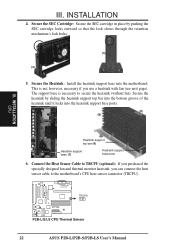
...you purchased the specially designed fan and thermal monitor heatsink, you use a heatsink with fan (see next page). TRCPU P2B-L/S/LS CPU Thermal Sensor 22 ASUS P2B-L/P2B-S/P2B-LS User's Manual Secure the SEC Cartridge: Secure the SEC cartridge in place by sliding the heatsink support top bar into... the bottom groove of the heatsink until it locks into the motherboard. Secure the heatsink by pushing the SEC ...
...you purchased the specially designed fan and thermal monitor heatsink, you use a heatsink with fan (see next page). TRCPU P2B-L/S/LS CPU Thermal Sensor 22 ASUS P2B-L/P2B-S/P2B-LS User's Manual Secure the SEC Cartridge: Secure the SEC cartridge in place by sliding the heatsink support top bar into... the bottom groove of the heatsink until it locks into the motherboard. Secure the heatsink by pushing the SEC ...
P2B-S User Manual
Page 23
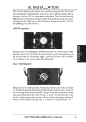
... from "Unlock" to clamp the heatsink into the SEC cartridge. The heatsink support top bar will not be connected to the CPU fan connector on motherboard. ASUS P2B-L/P2B-S/P2B-LS User's Manual 23 You will , however, still be included in the package, in case you use the heatsink support top bar because of the...
... from "Unlock" to clamp the heatsink into the SEC cartridge. The heatsink support top bar will not be connected to the CPU fan connector on motherboard. ASUS P2B-L/P2B-S/P2B-LS User's Manual 23 You will , however, still be included in the package, in case you use the heatsink support top bar because of the...

P2B-S User Manual
Page 24
...or software settings for your computer system's cover and the bracket plate on the slot with the screw you intend to PCI cards. Unplug your motherboard and expansion cards. Read the documentation for your used by a particular device (to use . In a standard design, there are 16 IRQs ...available but most of them are available to use at the same time. 24 ASUS P2B-L/P2B-S/P2B-LS User's Manual If your motherboard has audio onboard, an extra 3 IRQs will experience problems when those two devices are two types of your expansion card, such ...
...or software settings for your computer system's cover and the bracket plate on the slot with the screw you intend to PCI cards. Unplug your motherboard and expansion cards. Read the documentation for your used by a particular device (to use . In a standard design, there are 16 IRQs ...available but most of them are available to use at the same time. 24 ASUS P2B-L/P2B-S/P2B-LS User's Manual If your motherboard has audio onboard, an extra 3 IRQs will experience problems when those two devices are two types of your expansion card, such ...

P2B-S User Manual
Page 25
...To avoid conflicts, reserve the necessary IRQs and DMAs for an ISA Configuration Utility. INSTALLATION To simplify this process, this motherboard use this motherboard are assigned automatically from those used by legacy and PnP ISA cards. An IRQ number is added to set the ...those not used by legacy cards. R P2B-L/S/LS Accelerated Graphics Port (AGP) ASUS P2B-L/P2B-S/P2B-LS User's Manual 25 For PnP cards, IRQs are handled the same way as the ASUS AGP-V2740 3D Multimedia Accelerator. Accelerated Graphics Port This motherboard provides an accelerated graphics port (AGP) ...
...To avoid conflicts, reserve the necessary IRQs and DMAs for an ISA Configuration Utility. INSTALLATION To simplify this process, this motherboard use this motherboard are assigned automatically from those used by legacy and PnP ISA cards. An IRQ number is added to set the ...those not used by legacy cards. R P2B-L/S/LS Accelerated Graphics Port (AGP) ASUS P2B-L/P2B-S/P2B-LS User's Manual 25 For PnP cards, IRQs are handled the same way as the ASUS AGP-V2740 3D Multimedia Accelerator. Accelerated Graphics Port This motherboard provides an accelerated graphics port (AGP) ...

P2B-S User Manual
Page 26
...for a standard keyboard using a PS/2 plug (mini DIN). PS/2 Mouse Connector (6-pin Female) The system will direct IRQ12 to your motherboard. If not detected, expansion cards can use a DIN to the power connector on standard AT keyboards. The four corners of the connector. ...PS/2 Keyboard Connector (6-pin Female) This connection is detected. External Connectors WARNING! P2B-L/S/LS PS/2 Mouse (6-pin Female) 26 ASUS P2B-L/P2B-S/P2B-LS User's Manual This connector will cause damage to the PS/2 mouse if one is for connectors or power ...
...for a standard keyboard using a PS/2 plug (mini DIN). PS/2 Mouse Connector (6-pin Female) The system will direct IRQ12 to your motherboard. If not detected, expansion cards can use a DIN to the power connector on standard AT keyboards. The four corners of the connector. ...PS/2 Keyboard Connector (6-pin Female) This connection is detected. External Connectors WARNING! P2B-L/S/LS PS/2 Mouse (6-pin Female) 26 ASUS P2B-L/P2B-S/P2B-LS User's Manual This connector will cause damage to the PS/2 mouse if one is for connectors or power ...

P2B-S User Manual
Page 30
...50-pin)/Wide (68-pin)/Ultra2 (68-pin) SCSI Connectors This motherboard has onboard 50-Pin Fast SCSI connector for 8-bit SCSI devices, ... Wide SCSI Connector 1 50-pin Fast SCSI II Connector P2B-L/S/LS Onboard SCSI Connectors IMPORTANT: The 68-pin Wide SCSI Connector is easy and cost-effective. 30 ASUS P2B-L/P2B-S/P2B-LS User's Manual With Ultra2 devices, the SCSI bus ...Ultra2 SCSI Connector Wide SCSI Connector Adaptec AIC-3860 Chipset Single-Ended Devices CD-ROM Scanner Tape P2B-L/S/LS Mixed Ultra2 and Single-Ended Device Configuration Ultra2 SCSI uses the same connectors and cables as ...
...50-pin)/Wide (68-pin)/Ultra2 (68-pin) SCSI Connectors This motherboard has onboard 50-Pin Fast SCSI connector for 8-bit SCSI devices, ... Wide SCSI Connector 1 50-pin Fast SCSI II Connector P2B-L/S/LS Onboard SCSI Connectors IMPORTANT: The 68-pin Wide SCSI Connector is easy and cost-effective. 30 ASUS P2B-L/P2B-S/P2B-LS User's Manual With Ultra2 devices, the SCSI bus ...Ultra2 SCSI Connector Wide SCSI Connector Adaptec AIC-3860 Chipset Single-Ended Devices CD-ROM Scanner Tape P2B-L/S/LS Mixed Ultra2 and Single-Ended Device Configuration Ultra2 SCSI uses the same connectors and cables as ...


