
P2B-S User Manual
Page 3
...: +886-2-2894-3449 Email: info@asus.com.tw Technical Support Fax: +886-2-2895-9254 BBS: +886-2-2896-4667 Email: tsd@asus.com.tw WWW: www.asus.com.tw FTP: ftp.asus.com.tw/pub/ASUS ASUS COMPUTER INTERNATIONAL Marketing Address: 6737 Mowry ...ASUS ASUS COMPUTER GmbH Marketing Address: Harkort Str. 25, 40880 Ratingen, BRD, Germany Telephone: 49-2102-445011 Fax: 49-2102-442066 Email: info-ger@asus.com.tw Technical Support Hotline: 49-2102-499712 BBS: 49-2102-448690 Email: tsd-ger@asus.com.tw WWW: www.asuscom.de FTP: ftp.asuscom.de/pub/ASUSCOM ASUS P2B-L/P2B-S/P2B...
...: +886-2-2894-3449 Email: info@asus.com.tw Technical Support Fax: +886-2-2895-9254 BBS: +886-2-2896-4667 Email: tsd@asus.com.tw WWW: www.asus.com.tw FTP: ftp.asus.com.tw/pub/ASUS ASUS COMPUTER INTERNATIONAL Marketing Address: 6737 Mowry ...ASUS ASUS COMPUTER GmbH Marketing Address: Harkort Str. 25, 40880 Ratingen, BRD, Germany Telephone: 49-2102-445011 Fax: 49-2102-442066 Email: info-ger@asus.com.tw Technical Support Hotline: 49-2102-499712 BBS: 49-2102-448690 Email: tsd-ger@asus.com.tw WWW: www.asuscom.de FTP: ftp.asuscom.de/pub/ASUSCOM ASUS P2B-L/P2B-S/P2B...

P2B-S User Manual
Page 5
...Management Interface (DMI 60 VII. NETWORK INTERFACE Features 63 Software Driver Support 63 LED Connectors 64 DOS and Windows 3.1 Setup for DOS/Windows 3.1x Users 83 DOS Formatting Utilities 84 Low-level Formatter (scsifmt 84 Formatter and Partitioner (afdisk 85 ASUS P2B-L/P2B-S/P2B-LS User's Manual 5 ADAPTEC SCSI SELECT Configuring the SCSI Adapter...54 Load Setup Defaults 54 Supervisor Password and User Password 55 IDE HDD Auto Detection 56 Save & Exit Setup 57 Exit Without Saving 57 V. Support CD Support CD Main Menu 58 Main Menu Selections 59 Other CD Directories 59 VI.
...Management Interface (DMI 60 VII. NETWORK INTERFACE Features 63 Software Driver Support 63 LED Connectors 64 DOS and Windows 3.1 Setup for DOS/Windows 3.1x Users 83 DOS Formatting Utilities 84 Low-level Formatter (scsifmt 84 Formatter and Partitioner (afdisk 85 ASUS P2B-L/P2B-S/P2B-LS User's Manual 5 ADAPTEC SCSI SELECT Configuring the SCSI Adapter...54 Load Setup Defaults 54 Supervisor Password and User Password 55 IDE HDD Auto Detection 56 Save & Exit Setup 57 Exit Without Saving 57 V. Support CD Support CD Main Menu 58 Main Menu Selections 59 Other CD Directories 59 VI.
P2B-S User Manual
Page 7
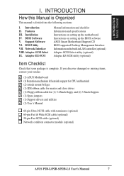
... SCSI Select utility (optional) Adaptec EZ-SCSI utility (optional) Item Checklist Check that your retailer. (1) ASUS Motherboard (1) Retention mechanism & heatsink support for CPU and heatsink (2) Attach mount bridges (1) IDE ribbon cable for master and slave drives (1) Floppy... (optional) Network condition connector module (optional) ASUS P2B-L/P2B-S/P2B-LS User's Manual 7 INTRODUCTION Manual / Checklist I . Installation IV. Instructions on setting up the BIOS software ASUS Smart Motherboard Support CD BIOS supported Desktop Management Interface Information on setting up the ...
... SCSI Select utility (optional) Adaptec EZ-SCSI utility (optional) Item Checklist Check that your retailer. (1) ASUS Motherboard (1) Retention mechanism & heatsink support for CPU and heatsink (2) Attach mount bridges (1) IDE ribbon cable for master and slave drives (1) Floppy... (optional) Network condition connector module (optional) ASUS P2B-L/P2B-S/P2B-LS User's Manual 7 INTRODUCTION Manual / Checklist I . Installation IV. Instructions on setting up the BIOS software ASUS Smart Motherboard Support CD BIOS supported Desktop Management Interface Information on setting up the ...
P2B-S User Manual
Page 8
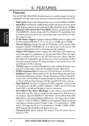
... and AIC-3860 transceiver chipset (optional) that supports four IDE devices in two channels, supports UltraDMA/33, PIO Modes 3 and 4 and Bus Master IDE DMA Mode 2, and supports Enhanced IDE devices. FEATURES Features The ASUS P2B-L/P2B-S/P2B-LS motherboards are carefully designed for the demanding ...of either 5.25inch or 3.5inch (1.44MB or 2.88MB) are also supported without affecting system performance by the fastest CPU. • Multi-Speed: Supports Intel Pentium® II processors from COM2 to CPU. 8 ASUS P2B-L/P2B-S/P2B-LS User's Manual UART2 can also be directed from 233MHz to ...
... and AIC-3860 transceiver chipset (optional) that supports four IDE devices in two channels, supports UltraDMA/33, PIO Modes 3 and 4 and Bus Master IDE DMA Mode 2, and supports Enhanced IDE devices. FEATURES Features The ASUS P2B-L/P2B-S/P2B-LS motherboards are carefully designed for the demanding ...of either 5.25inch or 3.5inch (1.44MB or 2.88MB) are also supported without affecting system performance by the fastest CPU. • Multi-Speed: Supports Intel Pentium® II processors from COM2 to CPU. 8 ASUS P2B-L/P2B-S/P2B-LS User's Manual UART2 can also be directed from 233MHz to ...
P2B-S User Manual
Page 9
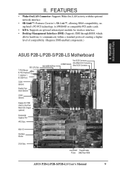
... optional infrared port module for wireless interface. • Desktop Management Interface (DMI): Supports DMI through BIOS, which allows hardware to communicate within a standard protocol creating a higher level of compatibility. (Requires DMI-enabled components.) II. FEATURES Motherboard Parts ASUS P2B-L/P2B-S/P2B-LS Motherboard SEC CPU Slot T: PS/2 Mouse B: PS/2 Keyboard T: USB Port ... Wide SCSI Chipset (optional) Accelerated Graphics Port 4PCI Slots Multi-I/O Hardware Monitor 2 ISA Slots Intel PIIX4E Programmable PCIset 2Mbit Flash ROM ASUS P2B-L/P2B-S/P2B-LS User's Manual 9 II.
... optional infrared port module for wireless interface. • Desktop Management Interface (DMI): Supports DMI through BIOS, which allows hardware to communicate within a standard protocol creating a higher level of compatibility. (Requires DMI-enabled components.) II. FEATURES Motherboard Parts ASUS P2B-L/P2B-S/P2B-LS Motherboard SEC CPU Slot T: PS/2 Mouse B: PS/2 Keyboard T: USB Port ... Wide SCSI Chipset (optional) Accelerated Graphics Port 4PCI Slots Multi-I/O Hardware Monitor 2 ISA Slots Intel PIIX4E Programmable PCIset 2Mbit Flash ROM ASUS P2B-L/P2B-S/P2B-LS User's Manual 9 II.
P2B-S User Manual
Page 11
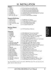
III. INSTALLATION Board Layout III. ASUS P2B-L/P2B-S/P2B-LS User's Manual 11 INSTALLATION Jumpers 1) CLRTC 2) KBPWR 3) LAN_EN 4) SCSI_EN 5) COMBINE 6) FS0, FS1, FS2 7) BF0, BF1, BF2, BF3 p. 13 Clear Real Time Clock (RTC) RAM p. ... Core:Bus Frequency Multiple Expansion Slots/Sockets 1) DIMM Sockets 2) SEC CPU Slot 3) SLOT1, SLOT2 4) PCI1, PCI2, PCI3, PCI4 5) AGP p. 18 DIMM Memory Support p. 19 Single Edge Contact CPU Support p. 24 16-bit ISA Bus Expansion Slots* p. 25 32-bit PCI Bus Expansion Slots† p. 25 Accelerated Graphics Port Hardware Monitor 1) TRCPU p. 22...
III. INSTALLATION Board Layout III. ASUS P2B-L/P2B-S/P2B-LS User's Manual 11 INSTALLATION Jumpers 1) CLRTC 2) KBPWR 3) LAN_EN 4) SCSI_EN 5) COMBINE 6) FS0, FS1, FS2 7) BF0, BF1, BF2, BF3 p. 13 Clear Real Time Clock (RTC) RAM p. ... Core:Bus Frequency Multiple Expansion Slots/Sockets 1) DIMM Sockets 2) SEC CPU Slot 3) SLOT1, SLOT2 4) PCI1, PCI2, PCI3, PCI4 5) AGP p. 18 DIMM Memory Support p. 19 Single Edge Contact CPU Support p. 24 16-bit ISA Bus Expansion Slots* p. 25 32-bit PCI Bus Expansion Slots† p. 25 Accelerated Graphics Port Hardware Monitor 1) TRCPU p. 22...

P2B-S User Manual
Page 13
...your computer and unplug its AC power, (2) Short the two solder points labeled CLRTC, (3) Turn on the +5VSB lead and the new ACPI BIOS support. The default is powered by pressing ) to re-enter user preferences. To clear the RTC data: (1) Turn off your computer, (4) Hold down... during bootup and enter BIOS setup to power up function. KBPWR 123 Disable (Default) KBPWR 123 Enable R P2B-L/S/LS Keyboard Power (Wake) Up ASUS P2B-L/P2B-S/P2B-LS User's Manual 13 Short the solder points to use your computer. Set to Enable if you to Disable because not all...
...your computer and unplug its AC power, (2) Short the two solder points labeled CLRTC, (3) Turn on the +5VSB lead and the new ACPI BIOS support. The default is powered by pressing ) to re-enter user preferences. To clear the RTC data: (1) Turn off your computer, (4) Hold down... during bootup and enter BIOS setup to power up function. KBPWR 123 Disable (Default) KBPWR 123 Enable R P2B-L/S/LS Keyboard Power (Wake) Up ASUS P2B-L/P2B-S/P2B-LS User's Manual 13 Short the solder points to use your computer. Set to Enable if you to Disable because not all...

P2B-S User Manual
Page 17
...) of the strict timing issues involved under "Chipset Features Setup". Memory speed setup is recommended through "Chipset Features Setup" in IV. ASUS P2B-L/P2B-S/P2B-LS User's Manual 17 Install memory in 32, 64, 128, 256MB sizes. INSTALLATION System Memory SDRAM DIMM (8 chips, Non-ECC)... chips/side + 1 ECC chip) and make the proper settings through SDRAM Configuration under this speed. • Two possible memory chips are supported: SDRAM with and without ECC. • SDRAM chips are generally thinner with higher pin density than traditional EDO (Extended Data Output) chips....
...) of the strict timing issues involved under "Chipset Features Setup". Memory speed setup is recommended through "Chipset Features Setup" in IV. ASUS P2B-L/P2B-S/P2B-LS User's Manual 17 Install memory in 32, 64, 128, 256MB sizes. INSTALLATION System Memory SDRAM DIMM (8 chips, Non-ECC)... chips/side + 1 ECC chip) and make the proper settings through SDRAM Configuration under this speed. • Two possible memory chips are supported: SDRAM with and without ECC. • SDRAM chips are generally thinner with higher pin density than traditional EDO (Extended Data Output) chips....
P2B-S User Manual
Page 18
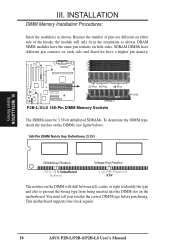
... DIMM will only fit in the orientation as shown. R III. DRAM SIMM modules have a higher pin density. 20 Pins 60 Pins 88 Pins Lock (FRONT) P2B-L/S/LS 168-Pin DIMM Memory Sockets The DIMMs must tell your retailer the correct DIMM type before purchasing. INSTALLATION DIMM Memory Installation Procedures: Insert the...-Pin DIMM Notch Key Definitions (3.3V) DRAM Key Position RFU Unbuffered Buffered Voltage Key Position 5.0V Reserved 3.3V The notches on the motherboard. This motherboard supports four clock signals. 18 ASUS P2B-L/P2B-S/P2B-LS User's Manual
... DIMM will only fit in the orientation as shown. R III. DRAM SIMM modules have a higher pin density. 20 Pins 60 Pins 88 Pins Lock (FRONT) P2B-L/S/LS 168-Pin DIMM Memory Sockets The DIMMs must tell your retailer the correct DIMM type before purchasing. INSTALLATION DIMM Memory Installation Procedures: Insert the...-Pin DIMM Notch Key Definitions (3.3V) DRAM Key Position RFU Unbuffered Buffered Voltage Key Position 5.0V Reserved 3.3V The notches on the motherboard. This motherboard supports four clock signals. 18 ASUS P2B-L/P2B-S/P2B-LS User's Manual
P2B-S User Manual
Page 19
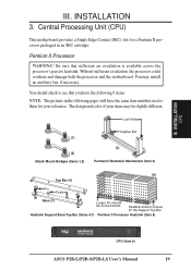
... (3) Pentium II Retention Mechanism (Item 3) (8) Top Bar (4) (5) Pin Posts (6) Base (7) Larger Fin should check to them for the Support Top Bar Heatsink Support Base/Top Bar (Items 4-7) Pentium II Processor Heatsink (Item 8) CPU (Item 9) ASUS P2B-L/P2B-S/P2B-LS User's Manual 19 You may be on the bottom. The design and color of your reference. INSTALLATION...
... (3) Pentium II Retention Mechanism (Item 3) (8) Top Bar (4) (5) Pin Posts (6) Base (7) Larger Fin should check to them for the Support Top Bar Heatsink Support Base/Top Bar (Items 4-7) Pentium II Processor Heatsink (Item 8) CPU (Item 9) ASUS P2B-L/P2B-S/P2B-LS User's Manual 19 You may be on the bottom. The design and color of your reference. INSTALLATION...
P2B-S User Manual
Page 22
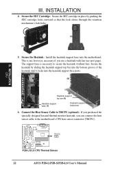
...Secure the SEC cartridge in place by sliding the heatsink support top bar into the bottom groove of the heatsink until it locks into the motherboard. The support base is not, however, necessary if you can connect...support base into the heatsink support base posts. (9) (8) R III. Secure the heatsink by pushing the SEC cartridge locks outward so that the lock shows through the retention mechanism's lock holes. (3) (3) 5. INSTALLATION CPU Heatsink support top bar (4) Heatsink support base (7) Heatsink support base post 6. TRCPU P2B-L/S/LS CPU Thermal Sensor 22 ASUS P2B-L/P2B-S/P2B...
...Secure the SEC cartridge in place by sliding the heatsink support top bar into the bottom groove of the heatsink until it locks into the motherboard. The support base is not, however, necessary if you can connect...support base into the heatsink support base posts. (9) (8) R III. Secure the heatsink by pushing the SEC cartridge locks outward so that the lock shows through the retention mechanism's lock holes. (3) (3) 5. INSTALLATION CPU Heatsink support top bar (4) Heatsink support base (7) Heatsink support base post 6. TRCPU P2B-L/S/LS CPU Thermal Sensor 22 ASUS P2B-L/P2B-S/P2B...
P2B-S User Manual
Page 23
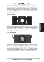
... hardware monitor, the ability to also use the alert function through the included LANDesk Client Manager (LDCM) software. ASUS P2B-L/P2B-S/P2B-LS User's Manual 23 INSTALLATION The heatsinks shown in case you use the heatsink support top bar because of proper heat dissipation and with three-pin fans that for installing the heatsink without...
... hardware monitor, the ability to also use the alert function through the included LANDesk Client Manager (LDCM) software. ASUS P2B-L/P2B-S/P2B-LS User's Manual 23 INSTALLATION The heatsinks shown in case you use the heatsink support top bar because of proper heat dissipation and with three-pin fans that for installing the heatsink without...

P2B-S User Manual
Page 25
...legacy and PnP ISA cards installed, IRQs are handled the same way as the ASUS AGP-V2740 3D Multimedia Accelerator. Accelerated Graphics Port This motherboard provides an accelerated graphics port (AGP) slot to support a new generation of the BIOS setup utility can select a DMA channel in ... to PCI expansion cards after those IRQs and DMAs you need to use a DMA (Direct Memory Access) channel. R P2B-L/S/LS Accelerated Graphics Port (AGP) ASUS P2B-L/P2B-S/P2B-LS User's Manual 25 ISA Cards and Hardware Monitor The onboard hardware monitor uses the address 290H-297H so legacy ISA...
...legacy and PnP ISA cards installed, IRQs are handled the same way as the ASUS AGP-V2740 3D Multimedia Accelerator. Accelerated Graphics Port This motherboard provides an accelerated graphics port (AGP) slot to support a new generation of the BIOS setup utility can select a DMA channel in ... to PCI expansion cards after those IRQs and DMAs you need to use a DMA (Direct Memory Access) channel. R P2B-L/S/LS Accelerated Graphics Port (AGP) ASUS P2B-L/P2B-S/P2B-LS User's Manual 25 ISA Cards and Hardware Monitor The onboard hardware monitor uses the address 290H-297H so legacy ISA...

P2B-S User Manual
Page 28
... optional network condition connector module. This module mounts to Pin 1 Floppy Drive Connector Pin 1 P2B-L/S/LS Floppy Disk Drive Connector 28 ASUS P2B-L/P2B-S/P2B-LS User's Manual Floppy Disk Drive Connector (34-1pin FLOPPY) This connector supports the provided floppy disk drive ribbon cable. After connecting the single end to the board, connect the two...
... optional network condition connector module. This module mounts to Pin 1 Floppy Drive Connector Pin 1 P2B-L/S/LS Floppy Disk Drive Connector 28 ASUS P2B-L/P2B-S/P2B-LS User's Manual Floppy Disk Drive Connector (34-1pin FLOPPY) This connector supports the provided floppy disk drive ribbon cable. After connecting the single end to the board, connect the two...

P2B-S User Manual
Page 29
...boot disk through BIOS Features Setup. If the COMBINE jumper is removed to blink. IDELED SCSILED P2B-L/S/LS IDE/SCSI Device Activity LED R ASUS P2B-L/P2B-S/P2B-LS User's Manual 29 Read and write activity by devices connected to blink. TIP: If ...the case-mounted LED does not light, try reversing the 2-pin plug. INSTALLATION 9. PIN 1 Primary IDE Connector Secondary IDE Connector III. Primary / Secondary IDE connectors (Two 40-1pin IDE) These connectors support...
...boot disk through BIOS Features Setup. If the COMBINE jumper is removed to blink. IDELED SCSILED P2B-L/S/LS IDE/SCSI Device Activity LED R ASUS P2B-L/P2B-S/P2B-LS User's Manual 29 Read and write activity by devices connected to blink. TIP: If ...the case-mounted LED does not light, try reversing the 2-pin plug. INSTALLATION 9. PIN 1 Primary IDE Connector Secondary IDE Connector III. Primary / Secondary IDE connectors (Two 40-1pin IDE) These connectors support...

P2B-S User Manual
Page 30
...onboard Adaptec AIC-7890AB chipset (optional) incorporates an advanced multimode I/O cell that supports both single-ended (SE) and Ultra2 devices. When an SE device is easy and cost-effective. 30 ASUS P2B-L/P2B-S/P2B-LS User's Manual By dividing the SCSI bus into independent SE and low ...voltage differential (LVD) segments, the transceiver chipset supports legacy devices without limiting performance and cable length on the LVD ...
...onboard Adaptec AIC-7890AB chipset (optional) incorporates an advanced multimode I/O cell that supports both single-ended (SE) and Ultra2 devices. When an SE device is easy and cost-effective. 30 ASUS P2B-L/P2B-S/P2B-LS User's Manual By dividing the SCSI bus into independent SE and low ...voltage differential (LVD) segments, the transceiver chipset supports legacy devices without limiting performance and cable length on the LVD ...

P2B-S User Manual
Page 31
...) or compatible PCI audio cards, enabling users to play Real-mode DOS games and multimedia applications. P2B-L/S/LS SB-LINK™ Connector ASUS P2B-L/P2B-S/P2B-LS User's Manual 31 IrDA-Compliant infrared module connector (5-pin IR) This connector supports the optional wireless transmitting and receiving infrared module. You must connect the optional Infrared (IrDA) module...
...) or compatible PCI audio cards, enabling users to play Real-mode DOS games and multimedia applications. P2B-L/S/LS SB-LINK™ Connector ASUS P2B-L/P2B-S/P2B-LS User's Manual 31 IrDA-Compliant infrared module connector (5-pin IR) This connector supports the optional wireless transmitting and receiving infrared module. You must connect the optional Infrared (IrDA) module...

P2B-S User Manual
Page 32
...KEYLOCK) This 2-pin connector connects to the case-mounted key switch to the case-mounted suspend switch. This function requires ACPI OS and driver support. 15. This 2-pin connector (see figure below) connects to allow keyboard locking. 20. ATX Power Switch / Soft Power Switch (PWR) ... KEYLOCK Ground +5V Ground Ground SPKR +5 V TB_LED ExtSMI# Ground PWR_SW +3VSB ResetCon Ground P2B-L/S/LS Panel Connectors Turbo LED Reset SW SMI Lead ATX Power Switch* * Requires an ATX power supply. 32 ASUS P2B-L/P2B-S/P2B-LS User's Manual R III. The LED will switch the system between ON and SLEEP. ...
...KEYLOCK) This 2-pin connector connects to the case-mounted key switch to the case-mounted suspend switch. This function requires ACPI OS and driver support. 15. This 2-pin connector (see figure below) connects to allow keyboard locking. 20. ATX Power Switch / Soft Power Switch (PWR) ... KEYLOCK Ground +5V Ground Ground SPKR +5 V TB_LED ExtSMI# Ground PWR_SW +3VSB ResetCon Ground P2B-L/S/LS Panel Connectors Turbo LED Reset SW SMI Lead ATX Power Switch* * Requires an ATX power supply. 32 ASUS P2B-L/P2B-S/P2B-LS User's Manual R III. The LED will switch the system between ON and SLEEP. ...

P2B-S User Manual
Page 33
...so that the chassis has been opened. III. Power Supply Fan Power CPU Fan Power Chassis Fan Power Rotation +12V Ground P2B-L/S/LS 12Volt Cooling Fan Power ASUS P2B-L/P2B-S/P2B-LS User's Manual 33 III. Chassis Open Alarm Lead (4-1 pin CHASSIS) This lead can be different. This function is .../or the CPU fan if these pins. INSTALLATION Connectors R R CHASSIS +5VSB CHASSIS GND P2B-L/S/LS Chassis Open Alarm Lead 22. Chassis/CPU/Power Supply Fan Connectors (3-pin FAN) These connectors support cooling fans of the this connector. Depending on the fan manufacturer, the wiring and plug ...
...so that the chassis has been opened. III. Power Supply Fan Power CPU Fan Power Chassis Fan Power Rotation +12V Ground P2B-L/S/LS 12Volt Cooling Fan Power ASUS P2B-L/P2B-S/P2B-LS User's Manual 33 III. Chassis Open Alarm Lead (4-1 pin CHASSIS) This lead can be different. This function is .../or the CPU fan if these pins. INSTALLATION Connectors R R CHASSIS +5VSB CHASSIS GND P2B-L/S/LS Chassis Open Alarm Lead 22. Chassis/CPU/Power Supply Fan Connectors (3-pin FAN) These connectors support cooling fans of the this connector. Depending on the fan manufacturer, the wiring and plug ...

P2B-S User Manual
Page 34
You may experience difficulty in one orientation because of the different hole sizes. INSTALLATION Connectors 34 ASUS P2B-L/P2B-S/P2B-LS User's Manual P2B-L/S/LS ATX Power Connector IMPORTANT: Make sure that the pins are aligned. +5.0 Volts +5.0 Volts -5.0 Volts Ground Ground Ground PWR Supply ... push down firmly but gently making sure that your ATX power supply must supply at least 10mA on your system if your power supply cannot support the load. +12.0Volts +5V Standby Power Good Ground +5.0 Volts Ground +5.0 Volts Ground +3.3 Volts +3.3 Volts R III. ATX Power Supply Connector...
You may experience difficulty in one orientation because of the different hole sizes. INSTALLATION Connectors 34 ASUS P2B-L/P2B-S/P2B-LS User's Manual P2B-L/S/LS ATX Power Connector IMPORTANT: Make sure that the pins are aligned. +5.0 Volts +5.0 Volts -5.0 Volts Ground Ground Ground PWR Supply ... push down firmly but gently making sure that your ATX power supply must supply at least 10mA on your system if your power supply cannot support the load. +12.0Volts +5V Standby Power Good Ground +5.0 Volts Ground +5.0 Volts Ground +3.3 Volts +3.3 Volts R III. ATX Power Supply Connector...


