
P2B-LS User Manual
Page 1
R P2B-L / P2B-S / P2B-LS Pentium® II Motherboards USER'S MANUAL Special Features ASUS P2B-L (power supply must provide at least 720mA on the +5VSB) • Intel 82558 LAN Chipset • Wake-On-LAN ASUS P2B-S • Adaptec 7890 SCSI Chipset • Adaptec 3860 SCSI Transceiver ASUS P2B-LS (power supply must provide at least 720mA on the +5VSB) • Intel 82558 LAN Chipset • Wake-On-LAN • Adaptec 7890 SCSI Chipset • Adaptec 3860 SCSI Transceiver
R P2B-L / P2B-S / P2B-LS Pentium® II Motherboards USER'S MANUAL Special Features ASUS P2B-L (power supply must provide at least 720mA on the +5VSB) • Intel 82558 LAN Chipset • Wake-On-LAN ASUS P2B-S • Adaptec 7890 SCSI Chipset • Adaptec 3860 SCSI Transceiver ASUS P2B-LS (power supply must provide at least 720mA on the +5VSB) • Intel 82558 LAN Chipset • Wake-On-LAN • Adaptec 7890 SCSI Chipset • Adaptec 3860 SCSI Transceiver
P2B-LS User Manual
Page 4
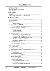
... Details of Chipset Features Setup 46 Power Management Setup 49 Details of Power Management Setup 49 4 ASUS P2B-L/P2B-S/P2B-LS User's Manual FEATURES Features 8 ASUS P2B-L/P2B-S/P2B-LS Motherboard 9 III. Jumpers 12 Jumper Settings 13 2. External Connectors 26 Power Connection Procedures 35 IV. INSTALLATION ASUS P2B-L/P2B-S/P2B-LS Motherboard Layout 10 Installation Steps 12 1. Expansion Cards 24 Expansion Card Installation Procedure 24 Assigning IRQs...
... Details of Chipset Features Setup 46 Power Management Setup 49 Details of Power Management Setup 49 4 ASUS P2B-L/P2B-S/P2B-LS User's Manual FEATURES Features 8 ASUS P2B-L/P2B-S/P2B-LS Motherboard 9 III. Jumpers 12 Jumper Settings 13 2. External Connectors 26 Power Connection Procedures 35 IV. INSTALLATION ASUS P2B-L/P2B-S/P2B-LS Motherboard Layout 10 Installation Steps 12 1. Expansion Cards 24 Expansion Card Installation Procedure 24 Assigning IRQs...
P2B-LS User Manual
Page 7
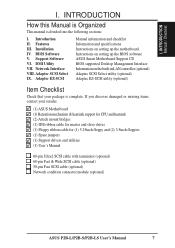
... (optional) Adaptec SCSI Select utility (optional) Adaptec EZ-SCSI utility (optional) Item Checklist Check that your retailer. (1) ASUS Motherboard (1) Retention mechanism & heatsink support for CPU and heatsink (2) Attach mount bridges (1) IDE ribbon cable for master and slave... connector module (optional) ASUS P2B-L/P2B-S/P2B-LS User's Manual 7 I . Introduction II. Features III. Network Interface VIII. INTRODUCTION Manual / Checklist I . Adaptec SCSI Select IX. Support Software VI. Instructions on setting up the BIOS software ASUS Smart Motherboard Support CD BIOS supported ...
... (optional) Adaptec SCSI Select utility (optional) Adaptec EZ-SCSI utility (optional) Item Checklist Check that your retailer. (1) ASUS Motherboard (1) Retention mechanism & heatsink support for CPU and heatsink (2) Attach mount bridges (1) IDE ribbon cable for master and slave... connector module (optional) ASUS P2B-L/P2B-S/P2B-LS User's Manual 7 I . Introduction II. Features III. Network Interface VIII. INTRODUCTION Manual / Checklist I . Adaptec SCSI Select IX. Support Software VI. Instructions on setting up the BIOS software ASUS Smart Motherboard Support CD BIOS supported ...
P2B-LS User Manual
Page 8
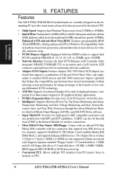
FEATURES Features The ASUS P2B-L/P2B-S/P2B-LS motherboards are also supported without affecting system performance by taking ...with EPP and ECP capabilities. BIOS supports IDE CD-ROM or SCSI device boot-up to CPU. 8 ASUS P2B-L/P2B-S/P2B-LS User's Manual Two floppy drives of low-voltage differential (LVD) technology. • AGP Slot: Supports ...System Resources Alert, and Virus Write Protection through the onboard Hardware Monitor, Intel LANDesk Client Manager (LDCM), and ASUS PC Probe software. • Super Multi-I /O subsystems and front-side bus (FSB) platform, which boosts the...
FEATURES Features The ASUS P2B-L/P2B-S/P2B-LS motherboards are also supported without affecting system performance by taking ...with EPP and ECP capabilities. BIOS supports IDE CD-ROM or SCSI device boot-up to CPU. 8 ASUS P2B-L/P2B-S/P2B-LS User's Manual Two floppy drives of low-voltage differential (LVD) technology. • AGP Slot: Supports ...System Resources Alert, and Virus Write Protection through the onboard Hardware Monitor, Intel LANDesk Client Manager (LDCM), and ASUS PC Probe software. • Super Multi-I /O subsystems and front-side bus (FSB) platform, which boosts the...
P2B-LS User Manual
Page 9
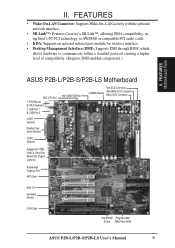
II. FEATURES Motherboard Parts ASUS P2B-L/P2B-S/P2B-LS Motherboard SEC CPU Slot T: PS/2 Mouse B: PS/2 Keyboard T: USB Port 1 B: USB Port 2 COM 1 (Bottom) Parallel (Top) Serial (Bottom) COM 2 (Bottom) Intel 440BX AGPset Fast-SCSI... Ultra2 & Ultra-Fast/ Wide SCSI Chipset (optional) Accelerated Graphics Port 4PCI Slots Multi-I/O Hardware Monitor 2 ISA Slots Intel PIIX4E Programmable PCIset 2Mbit Flash ROM ASUS P2B-L/P2B-S/P2B-LS User's Manual 9 FEATURES • Wake-On-LAN Connector: Supports Wake-On-LAN activity with the optional network interface. • SB-Link™: Features ...
II. FEATURES Motherboard Parts ASUS P2B-L/P2B-S/P2B-LS Motherboard SEC CPU Slot T: PS/2 Mouse B: PS/2 Keyboard T: USB Port 1 B: USB Port 2 COM 1 (Bottom) Parallel (Top) Serial (Bottom) COM 2 (Bottom) Intel 440BX AGPset Fast-SCSI... Ultra2 & Ultra-Fast/ Wide SCSI Chipset (optional) Accelerated Graphics Port 4PCI Slots Multi-I/O Hardware Monitor 2 ISA Slots Intel PIIX4E Programmable PCIset 2Mbit Flash ROM ASUS P2B-L/P2B-S/P2B-LS User's Manual 9 FEATURES • Wake-On-LAN Connector: Supports Wake-On-LAN activity with the optional network interface. • SB-Link™: Features ...
P2B-LS User Manual
Page 10
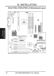
INSTALLATION Board Layout 10 ASUS P2B-L/P2B-S/P2B-LS User's Manual III. Ratio ASUS A97127F Chipset BF3 BF2 BF1 BF0 BIOS Power (CR2032 3V Lithium Cell) SCSILED CHASSIS WOL_CON EXTBATT 2Mbit Flash EEPROM (Programmable BIOS) CHA_FAN PANEL...Monitor PCI Slot 1 ISA Slot 1 ISA Slot 2 SCSI_EN Adaptec SCSI Chipset Adaptec AIC-3860 Chipset SECONDARY IDE 1 PRIMARY IDE Intel PIIX4E Chipset CLRTC 1 Freq. INSTALLATION ASUS P2B-L/P2B-S/P2B-LS Motherboard Layout DIMM Socket 0 (64/72 bit, 168 pin module) DIMM Socket 1 (64/72 bit, 168 pin module) DIMM Socket 2 (64/72 bit, 168 ...
INSTALLATION Board Layout 10 ASUS P2B-L/P2B-S/P2B-LS User's Manual III. Ratio ASUS A97127F Chipset BF3 BF2 BF1 BF0 BIOS Power (CR2032 3V Lithium Cell) SCSILED CHASSIS WOL_CON EXTBATT 2Mbit Flash EEPROM (Programmable BIOS) CHA_FAN PANEL...Monitor PCI Slot 1 ISA Slot 1 ISA Slot 2 SCSI_EN Adaptec SCSI Chipset Adaptec AIC-3860 Chipset SECONDARY IDE 1 PRIMARY IDE Intel PIIX4E Chipset CLRTC 1 Freq. INSTALLATION ASUS P2B-L/P2B-S/P2B-LS Motherboard Layout DIMM Socket 0 (64/72 bit, 168 pin module) DIMM Socket 1 (64/72 bit, 168 pin module) DIMM Socket 2 (64/72 bit, 168 ...

P2B-LS User Manual
Page 11
... Open Alarm Lead (4-1 pins) 22) CHA_/CPU_/PWR_FAN p. 33 Chassis/CPU/Power Supply Fan Connectors (3 pins) 23) ATXPWR p. 34 ATX Motherboard Power Connector (20 pins) *The onboard hardware monitor uses the address 290H-297H so legacy ISA cards must not use this address, otherwise conflicts will occur. ASUS P2B-L/P2B-S/P2B-LS User's Manual 11 III.
... Open Alarm Lead (4-1 pins) 22) CHA_/CPU_/PWR_FAN p. 33 Chassis/CPU/Power Supply Fan Connectors (3 pins) 23) ATXPWR p. 34 ATX Motherboard Power Connector (20 pins) *The onboard hardware monitor uses the address 290H-297H so legacy ISA cards must not use this address, otherwise conflicts will occur. ASUS P2B-L/P2B-S/P2B-LS User's Manual 11 III.
P2B-LS User Manual
Page 12
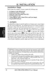
...5. See motherboard layout for no connection, connect pins 1&2, and connect pins 2&3, respectively. For manufacturing simplicity, the jumpers may be shown as SCSI cards, contain very delicate Integrated Circuit (IC) chips. To protect them against damage from the system. 12 ASUS P2B-L/P2B-S/P2B-LS User's ... steps: 1. INSTALLATION Installation Steps Before using your hands to a safely grounded object or to connect jumper pins (JP) on the motherboard. Connect Ribbon Cables, Cabinet Wires, and Power Supply 6. Use the diagrams in this manual instead of jumpers. Settings with two jumper...
...5. See motherboard layout for no connection, connect pins 1&2, and connect pins 2&3, respectively. For manufacturing simplicity, the jumpers may be shown as SCSI cards, contain very delicate Integrated Circuit (IC) chips. To protect them against damage from the system. 12 ASUS P2B-L/P2B-S/P2B-LS User's ... steps: 1. INSTALLATION Installation Steps Before using your hands to a safely grounded object or to connect jumper pins (JP) on the motherboard. Connect Ribbon Cables, Cabinet Wires, and Power Supply 6. Use the diagrams in this manual instead of jumpers. Settings with two jumper...

P2B-LS User Manual
Page 14
...LED Selection (COMBINE) The IDE and SCSI Activity LEDs normally has separate connections. LAN_EN 1 2 3 Enable (Default) LAN_EN 1 2 3 Disable P2B-L/S/LS Onboard LAN Setting 4. If you have one LED on your system cabinet, place a jumper on COMBINE in order to combine the IDE and SCSI... are separate COMBINE IDELED includes SCSILED activity P2B-L/S/LS IDE/SCSI Device Activity LED Selection 14 ASUS P2B-L/P2B-S/P2B-LS User's Manual Onboard LAN Setting (LAN_EN) The onboard Intel 10/100 Fast Ethernet may be enabled or disabled using this motherboard but only have both SCSI and IDE devices...
...LED Selection (COMBINE) The IDE and SCSI Activity LEDs normally has separate connections. LAN_EN 1 2 3 Enable (Default) LAN_EN 1 2 3 Disable P2B-L/S/LS Onboard LAN Setting 4. If you have one LED on your system cabinet, place a jumper on COMBINE in order to combine the IDE and SCSI... are separate COMBINE IDELED includes SCSILED activity P2B-L/S/LS IDE/SCSI Device Activity LED Selection 14 ASUS P2B-L/P2B-S/P2B-LS User's Manual Onboard LAN Setting (LAN_EN) The onboard Intel 10/100 Fast Ethernet may be enabled or disabled using this motherboard but only have both SCSI and IDE devices...
P2B-LS User Manual
Page 17
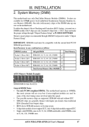
... specification. INSTALLATION System Memory SDRAM DIMM (8 chips, Non-ECC) General DIMM Notes • Use only PC100-compliant DIMMs. This motherboard operates at 100MHz, thus most systems will not even boot if non-compliant modules are used must use a DIMM module with higher...x1 Socket 4 (Rows 6&7) SDRAM 8, 16, 32, 64, 128, 256MB x1 Total System Memory (Max 1024MB) = ASUS Memory Module Example: III. Install memory in 32, 64, 128, 256MB sizes. ASUS P2B-L/P2B-S/P2B-LS User's Manual 17 Sockets are generally thinner with 9 chips per side (standard 8 chips/side + 1 ECC chip) ...
... specification. INSTALLATION System Memory SDRAM DIMM (8 chips, Non-ECC) General DIMM Notes • Use only PC100-compliant DIMMs. This motherboard operates at 100MHz, thus most systems will not even boot if non-compliant modules are used must use a DIMM module with higher...x1 Socket 4 (Rows 6&7) SDRAM 8, 16, 32, 64, 128, 256MB x1 Total System Memory (Max 1024MB) = ASUS Memory Module Example: III. Install memory in 32, 64, 128, 256MB sizes. ASUS P2B-L/P2B-S/P2B-LS User's Manual 17 Sockets are generally thinner with 9 chips per side (standard 8 chips/side + 1 ECC chip) ...

P2B-LS User Manual
Page 18
...Voltage Key Position 5.0V Reserved 3.3V The notches on the DIMM will only fit in the orientation as shown. This motherboard supports four clock signals. 18 ASUS P2B-L/P2B-S/P2B-LS User's Manual Because the number of the breaks, the module will shift between left, center, or right to identify the... type and also to prevent the wrong type from being inserted into the DIMM slot on the motherboard. DRAM SIMM modules have ...
...Voltage Key Position 5.0V Reserved 3.3V The notches on the DIMM will only fit in the orientation as shown. This motherboard supports four clock signals. 18 ASUS P2B-L/P2B-S/P2B-LS User's Manual Because the number of the breaks, the module will shift between left, center, or right to identify the... type and also to prevent the wrong type from being inserted into the DIMM slot on the motherboard. DRAM SIMM modules have ...

P2B-LS User Manual
Page 19
...numbers next to see that sufficient air circulation is available across the processor's passive heatsink. Central Processing Unit (CPU) This motherboard provides a Single Edge Contact (SEC) slot for your items may install an auxiliary fan, if necessary. Pentium II Processor...could overheat and damage both the processor and the motherboard. You should be slightly different. Heatsink bottom Groove for the Support Top Bar Heatsink Support Base/Top Bar (Items 4-7) Pentium II Processor Heatsink (Item 8) CPU (Item 9) ASUS P2B-L/P2B-S/P2B-LS User's Manual 19 Lock Holes (1) (2) Attach...
...numbers next to see that sufficient air circulation is available across the processor's passive heatsink. Central Processing Unit (CPU) This motherboard provides a Single Edge Contact (SEC) slot for your items may install an auxiliary fan, if necessary. Pentium II Processor...could overheat and damage both the processor and the motherboard. You should be slightly different. Heatsink bottom Groove for the Support Top Bar Heatsink Support Base/Top Bar (Items 4-7) Pentium II Processor Heatsink (Item 8) CPU (Item 9) ASUS P2B-L/P2B-S/P2B-LS User's Manual 19 Lock Holes (1) (2) Attach...

P2B-LS User Manual
Page 20
... are the screws from the mount bridges (1 & 2) Attach Mount Bridges (underside) III. Lock holes Captive nut Captive nut 20 ASUS P2B-L/P2B-S/P2B-LS User's Manual TIP: Orient the mechanism's lock holes toward the motherboard's chipset (see motherboard layout for the location of the slot and that the mechanism is designed to no more than 6±1 inch...
... are the screws from the mount bridges (1 & 2) Attach Mount Bridges (underside) III. Lock holes Captive nut Captive nut 20 ASUS P2B-L/P2B-S/P2B-LS User's Manual TIP: Orient the mechanism's lock holes toward the motherboard's chipset (see motherboard layout for the location of the slot and that the mechanism is designed to no more than 6±1 inch...

P2B-LS User Manual
Page 21
... two locks inward (the preceding picture shows the locks in the outward position and inward in the picture below). With the heatsink facing the motherboard's chipsets, press the cartridge gently but firmly until they lock (8) Lock Lock Push Clamp (9) The thermal pad & SEC cartridge should not...If the heatsink is firmly pressed against the pictures. The thicker fin must be orientated toward the bottom. Push lock inward (3) ASUS P2B-L/P2B-S/P2B-LS User's Manual 21 The top clamp is full inserted. INSTALLATION CPU III. Check the orientation of the clamps until it is wider...
... two locks inward (the preceding picture shows the locks in the outward position and inward in the picture below). With the heatsink facing the motherboard's chipsets, press the cartridge gently but firmly until they lock (8) Lock Lock Push Clamp (9) The thermal pad & SEC cartridge should not...If the heatsink is firmly pressed against the pictures. The thicker fin must be orientated toward the bottom. Push lock inward (3) ASUS P2B-L/P2B-S/P2B-LS User's Manual 21 The top clamp is full inserted. INSTALLATION CPU III. Check the orientation of the clamps until it is wider...

P2B-LS User Manual
Page 22
This is necessary to secure the heatsink (without fan). TRCPU P2B-L/S/LS CPU Thermal Sensor 22 ASUS P2B-L/P2B-S/P2B-LS User's Manual INSTALLATION 4. Secure the Heatsink: Install the heatsink support base into the heatsink support base posts. (9) (8) R III. Secure the heatsink by pushing...Secure the SEC cartridge in place by sliding the heatsink support top bar into the bottom groove of the heatsink until it locks into the motherboard. The support base is not, however, necessary if you can connect the heat sensor cable to TRCPU (optional): If you purchased the specially...
This is necessary to secure the heatsink (without fan). TRCPU P2B-L/S/LS CPU Thermal Sensor 22 ASUS P2B-L/P2B-S/P2B-LS User's Manual INSTALLATION 4. Secure the Heatsink: Install the heatsink support base into the heatsink support base posts. (9) (8) R III. Secure the heatsink by pushing...Secure the SEC cartridge in place by sliding the heatsink support top bar into the bottom groove of the heatsink until it locks into the motherboard. The support base is not, however, necessary if you can connect the heat sensor cable to TRCPU (optional): If you purchased the specially...

P2B-LS User Manual
Page 23
...the heatsink support top bar because of proper heat dissipation and with a lever to use the heatsink support top bar because of the fan. ASUS P2B-L/P2B-S/P2B-LS User's Manual 23 The heatsink support top bar will , however, still be included in the package, in the orientation as that can be... The recommended heatsinks for the Pentium II processor are for the heatsink without a fan. You will not be able to the CPU fan connector on motherboard. You will not, however, be connected to also use a heatsink without a fan. These heatsinks have the added benefits of the fan. III...
...the heatsink support top bar because of proper heat dissipation and with a lever to use the heatsink support top bar because of the fan. ASUS P2B-L/P2B-S/P2B-LS User's Manual 23 The heatsink support top bar will , however, still be included in the package, in the orientation as that can be... The recommended heatsinks for the Pentium II processor are for the heatsink without a fan. You will not be able to the CPU fan connector on motherboard. You will not, however, be connected to also use a heatsink without a fan. These heatsinks have the added benefits of the fan. III...
P2B-LS User Manual
Page 24
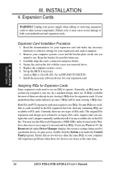
... remaining IRQs are two types of them are in the ISA expansion bus first, then any necessary hardware or software settings for your motherboard and expansion cards. Remove your expansion card. Carefully align the card's connectors and press firmly. 4. Install the necessary software drivers for...the Resources tab under Device Manager displays the resource settings being used by a particular device (to use at the same time. 24 ASUS P2B-L/P2B-S/P2B-LS User's Manual You may require to gain access, double-click the System icon under the Control Panel program). Secure the card on ...
... remaining IRQs are two types of them are in the ISA expansion bus first, then any necessary hardware or software settings for your motherboard and expansion cards. Remove your expansion card. Carefully align the card's connectors and press firmly. 4. Install the necessary software drivers for...the Resources tab under Device Manager displays the resource settings being used by a particular device (to use at the same time. 24 ASUS P2B-L/P2B-S/P2B-LS User's Manual You may require to gain access, double-click the System icon under the Control Panel program). Secure the card on ...
P2B-LS User Manual
Page 25
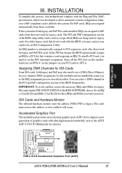
... In the PCI bus design, the BIOS automatically assigns an IRQ to INT A. Since all the PCI slots on this motherboard use an INTA #, set the INT (interrupt) assignment. DMA assignments for an ISA Configuration Utility. INSTALLATION AGP III. ...ASUS AGP-V2740 3D Multimedia Accelerator. R P2B-L/S/LS Accelerated Graphics Port (AGP) ASUS P2B-L/P2B-S/P2B-LS User's Manual 25 An IRQ number is added to PCI expansion cards after those not used by legacy cards. INSTALLATION To simplify this process, this address or else conflicts will occur. Accelerated Graphics Port This motherboard...
... In the PCI bus design, the BIOS automatically assigns an IRQ to INT A. Since all the PCI slots on this motherboard use an INTA #, set the INT (interrupt) assignment. DMA assignments for an ISA Configuration Utility. INSTALLATION AGP III. ...ASUS AGP-V2740 3D Multimedia Accelerator. R P2B-L/S/LS Accelerated Graphics Port (AGP) ASUS P2B-L/P2B-S/P2B-LS User's Manual 25 An IRQ number is added to PCI expansion cards after those not used by legacy cards. INSTALLATION To simplify this process, this address or else conflicts will occur. Accelerated Graphics Port This motherboard...
P2B-LS User Manual
Page 26
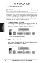
... Control" in BIOS Features Setup of the connectors are used for a standard keyboard using a PS/2 plug (mini DIN). P2B-L/S/LS PS/2 Mouse (6-pin Female) 26 ASUS P2B-L/P2B-S/P2B-LS User's Manual PS/2 Mouse Connector (6-pin Female) The system will not allow standard AT size (large DIN) keyboard plugs...., expansion cards can use a DIN to the power connector on the motherboard. III. External Connectors WARNING! The four corners of the BIOS SOFTWARE. This connector will direct IRQ12 to your motherboard. IMPORTANT: Ribbon cables should always be less than 46cm(18in), with the...
... Control" in BIOS Features Setup of the connectors are used for a standard keyboard using a PS/2 plug (mini DIN). P2B-L/S/LS PS/2 Mouse (6-pin Female) 26 ASUS P2B-L/P2B-S/P2B-LS User's Manual PS/2 Mouse Connector (6-pin Female) The system will not allow standard AT size (large DIN) keyboard plugs...., expansion cards can use a DIN to the power connector on the motherboard. III. External Connectors WARNING! The four corners of the BIOS SOFTWARE. This connector will direct IRQ12 to your motherboard. IMPORTANT: Ribbon cables should always be less than 46cm(18in), with the...

P2B-LS User Manual
Page 30
... 35 1 68 34 68-pin Wide SCSI Connector 1 50-pin Fast SCSI II Connector P2B-L/S/LS Onboard SCSI Connectors IMPORTANT: The 68-pin Wide SCSI Connector is easy and cost-effective. 30 ASUS P2B-L/P2B-S/P2B-LS User's Manual In mixed environments of Ultra2 and SE devices, the onboard host adapter can ...Scanner Tape P2B-L/S/LS Mixed Ultra2 and Single-Ended Device Configuration Ultra2 SCSI uses the same connectors and cables as UltraSCSI, so upgrading is always terminated and will only work as an end device. Fast (50-pin)/Wide (68-pin)/Ultra2 (68-pin) SCSI Connectors This motherboard has ...
... 35 1 68 34 68-pin Wide SCSI Connector 1 50-pin Fast SCSI II Connector P2B-L/S/LS Onboard SCSI Connectors IMPORTANT: The 68-pin Wide SCSI Connector is easy and cost-effective. 30 ASUS P2B-L/P2B-S/P2B-LS User's Manual In mixed environments of Ultra2 and SE devices, the onboard host adapter can ...Scanner Tape P2B-L/S/LS Mixed Ultra2 and Single-Ended Device Configuration Ultra2 SCSI uses the same connectors and cables as UltraSCSI, so upgrading is always terminated and will only work as an end device. Fast (50-pin)/Wide (68-pin)/Ultra2 (68-pin) SCSI Connectors This motherboard has ...


