
User Manual
Page 5
...Boot Settings Configuration 4-36 4.8 Exit menu 4-37 Chapter 5: RAID configuration 5.1 Setting up RAID 5-1 5.1.1 RAID definitions 5-1 5.1.2 Installing hard disk drives 5-2 5.1.3 Setting the RAID item in BIOS 5-2 5.1.4 RAID configuration utilities 5-3 5.2 LSI Logic Embedded SATA RAID Setup Utility 5-4 ...spare drive 5-41 5.4.8 Deleting a RAID set 5-43 5.4.9 Rebuilding a RAID set 5-44 5.4.10 Verifying a RAID set hard disk drive 5-45 5.4.11 Making a RAID set bootable 5-46 5.5 Adaptec® RAID Configuration Utility (NCLV-D2/SATA model only 5-48 5.5.1 Configuring the hard disk drive(s...
...Boot Settings Configuration 4-36 4.8 Exit menu 4-37 Chapter 5: RAID configuration 5.1 Setting up RAID 5-1 5.1.1 RAID definitions 5-1 5.1.2 Installing hard disk drives 5-2 5.1.3 Setting the RAID item in BIOS 5-2 5.1.4 RAID configuration utilities 5-3 5.2 LSI Logic Embedded SATA RAID Setup Utility 5-4 ...spare drive 5-41 5.4.8 Deleting a RAID set 5-43 5.4.9 Rebuilding a RAID set 5-44 5.4.10 Verifying a RAID set hard disk drive 5-45 5.4.11 Making a RAID set bootable 5-46 5.5 Adaptec® RAID Configuration Utility (NCLV-D2/SATA model only 5-48 5.5.1 Configuring the hard disk drive(s...
User Manual
Page 12
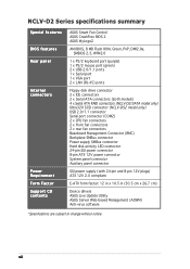
... Fan Control ASUS CrashFree BIOS 2 ASUS MyLogo2 AMI BIOS, 8 MB Flash ROM, Green, PnP, DMI2.0a, SMBIOS 2.3, WfM2.0 1 x PS/2 keyboard port (purple) 1 x PS/2 mouse port (green) 2 x USB 2.0/1.1 ports 1 x Serial port 1 x VGA port 2 x LAN (RJ-45) ports Floppy disk drive connector 2 x IDE connectors 2 x Serial ATA connectors (both models) 4 x Serial ATA RAID connectors (NCLV-D2/SATA model...
... Fan Control ASUS CrashFree BIOS 2 ASUS MyLogo2 AMI BIOS, 8 MB Flash ROM, Green, PnP, DMI2.0a, SMBIOS 2.3, WfM2.0 1 x PS/2 keyboard port (purple) 1 x PS/2 mouse port (green) 2 x USB 2.0/1.1 ports 1 x Serial port 1 x VGA port 2 x LAN (RJ-45) ports Floppy disk drive connector 2 x IDE connectors 2 x Serial ATA connectors (both models) 4 x Serial ATA RAID connectors (NCLV-D2/SATA model...
User Manual
Page 16
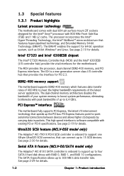
...the interface for PCI 2.3. The dual-channel memory architecture doubles the bandwidth of your system memory to 15 SCSI devices. Ultra320 SCSI feature (NCLV-DS2 model only) The Adaptec® AIC-7901X PCI-X SCSI controller is software compatible with 800 MHz Front Side Bus (FSB) and ...four SATA II hard disk drives with peak bandwidths of the latest server applications. The SATA II specification allows up to support one 68-pin Ultra320 SCSI connector, that features hyper-pipelined technology, and Extended Memory 64-bit Technology (EM64T). Serial ATA II feature (NCLV-D2/SATA model only)...
...the interface for PCI 2.3. The dual-channel memory architecture doubles the bandwidth of your system memory to 15 SCSI devices. Ultra320 SCSI feature (NCLV-DS2 model only) The Adaptec® AIC-7901X PCI-X SCSI controller is software compatible with 800 MHz Front Side Bus (FSB) and ...four SATA II hard disk drives with peak bandwidths of the latest server applications. The SATA II specification allows up to support one 68-pin Ultra320 SCSI connector, that features hyper-pipelined technology, and Extended Memory 64-bit Technology (EM64T). Serial ATA II feature (NCLV-D2/SATA model only)...

User Manual
Page 47
... drive connector 2 . NCLV-D2 Series IDE connectors ASUS NCLV-D2 Series 2-27 Floppy disk drive connector (34-1 pin FLOPPY) This connector is removed to PIN 1. The Ultra DMA 100/66 signal cable has three connectors: a blue connector for the primary IDE connector on the motherboard, a black connector for an Ultra DMA 100/66 IDE slave device (optical drive/hard...
... drive connector 2 . NCLV-D2 Series IDE connectors ASUS NCLV-D2 Series 2-27 Floppy disk drive connector (34-1 pin FLOPPY) This connector is removed to PIN 1. The Ultra DMA 100/66 signal cable has three connectors: a blue connector for the primary IDE connector on the motherboard, a black connector for an Ultra DMA 100/66 IDE slave device (optical drive/hard...
User Manual
Page 48
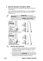
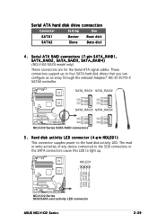
... GND SATA1 NCLV-D2/SATA SATA connectors GND RSATA_TXP1 RSATA_TXN1 GND RSATA_RXP1 RSATA_RXN1 GND SATA2 GND RSATA_TXP2 RSATA_TXN2 GND RSATA_RXP2 RSATA_RXN2 GND NCLV-DS2 SATA connectors SATA1 GND RSATA_TXP1 RSATA_TXN1 GND RSATA_RXP1 RSATA_RXN1 GND Important notes on the next page for Serial ATA hard disk drives. 3 ...feature (RAID 0 or RAID 1) is available only if you can connect Serial ATA boot/data hard disk drives to the SATA1 connector. Serial ATA connectors (7-pin SATA1, SATA2) These connectors are set . • When using these connectors. Refer to [Yes]. These ...
... GND SATA1 NCLV-D2/SATA SATA connectors GND RSATA_TXP1 RSATA_TXN1 GND RSATA_RXP1 RSATA_RXN1 GND SATA2 GND RSATA_TXP2 RSATA_TXN2 GND RSATA_RXP2 RSATA_RXN2 GND NCLV-DS2 SATA connectors SATA1 GND RSATA_TXP1 RSATA_TXN1 GND RSATA_RXP1 RSATA_RXN1 GND Important notes on the next page for Serial ATA hard disk drives. 3 ...feature (RAID 0 or RAID 1) is available only if you can connect Serial ATA boot/data hard disk drives to the SATA1 connector. Serial ATA connectors (7-pin SATA1, SATA2) These connectors are set . • When using these connectors. Refer to [Yes]. These ...
User Manual
Page 49
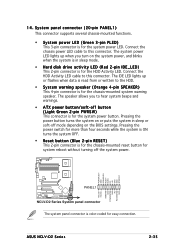
HDLED1 1 SCSI_ACTLED+ SCSI_ACTLEDSCSI_ACTLEDSCSI_ACTLED+ NCLV-D2 Series SCSI/SATA card activity LED connector ASUS NCLV-D2 Series 2-29 Hard disk activity LED connector (4-pin HDLED1) This connector supplies power to light up to four SATA hard disk drives that you can configure as an array...SATA_RAID3 SATA_RAID4 GND RSATA_TXP1 RSATA_TXN1 GND RSATA_RXP1 RSATA_RXN1 GND NCLV-D2 Series SATA RAID connectors GND RSATA_TXP2 RSATA_TXN2 GND RSATA_RXP2 RSATA_RXN2 GND 5 . Serial ATA hard disk drive connection Connector Setting Use SATA1 Master Boot disk SATA2 Slave Data disk 4 .
HDLED1 1 SCSI_ACTLED+ SCSI_ACTLEDSCSI_ACTLEDSCSI_ACTLED+ NCLV-D2 Series SCSI/SATA card activity LED connector ASUS NCLV-D2 Series 2-29 Hard disk activity LED connector (4-pin HDLED1) This connector supplies power to light up to four SATA hard disk drives that you can configure as an array...SATA_RAID3 SATA_RAID4 GND RSATA_TXP1 RSATA_TXN1 GND RSATA_RXP1 RSATA_RXN1 GND NCLV-D2 Series SATA RAID connectors GND RSATA_TXP2 RSATA_TXN2 GND RSATA_RXP2 RSATA_RXN2 GND 5 . Serial ATA hard disk drive connection Connector Setting Use SATA1 Master Boot disk SATA2 Slave Data disk 4 .
User Manual
Page 55
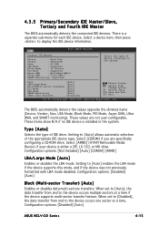
...Hard disk drive activity LED (Red 2-pin IDE_LED) This 2-pin connector is color-coded for the HDD Activity LED. The speaker allows you turn on the BIOS settings. 14. POWERLED+ GND POWERLEDMLED+ MLEDNC +5V GND GND SPKROUT HDLED+ HDLEDNMIBTN# GND POWERBTN# GND NC RESETBTN# GND PANEL1 NCLV-D2... Series System panel connector The system panel connector is for easy connection. ASUS NCLV-D2 Series 2-35 The system power LED lights up or flashes when data is for the system power...
...Hard disk drive activity LED (Red 2-pin IDE_LED) This 2-pin connector is color-coded for the HDD Activity LED. The speaker allows you turn on the BIOS settings. 14. POWERLED+ GND POWERLEDMLED+ MLEDNC +5V GND GND SPKROUT HDLED+ HDLEDNMIBTN# GND POWERBTN# GND NC RESETBTN# GND PANEL1 NCLV-D2... Series System panel connector The system panel connector is for easy connection. ASUS NCLV-D2 Series 2-35 The system power LED lights up or flashes when data is for the system power...

User Manual
Page 66
A:\>afudos /iNCLVDS2.ROM AMI Firmware Update Utility - done Writing flash ...... Reboot the system from the hard disk drive. All rights reserved. Do not turn off power during flash BIOS Reading file ....... Version 1.19(ASUS V2.07(03.11.24BB)) Copyright (C) 2002 American Megatrends, Inc. Erasing flash ...... The utility returns to the DOS prompt after the BIOS update process is completed. WARNING!! done Reading flash ...... done Verifying flash .... done Please restart your computer A:\> 4-4 Chapter 4: BIOS setup done Advance Check ...... 5.
A:\>afudos /iNCLVDS2.ROM AMI Firmware Update Utility - done Writing flash ...... Reboot the system from the hard disk drive. All rights reserved. Do not turn off power during flash BIOS Reading file ....... Version 1.19(ASUS V2.07(03.11.24BB)) Copyright (C) 2002 American Megatrends, Inc. Erasing flash ...... The utility returns to the DOS prompt after the BIOS update process is completed. WARNING!! done Reading flash ...... done Verifying flash .... done Please restart your computer A:\> 4-4 Chapter 4: BIOS setup done Advance Check ...... 5.
User Manual
Page 77
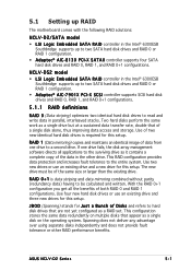
...to the device occurs multiple sectors at a time. Configuration options: [Disabled] [Auto] ASUS NCLV-D2 Series 4-15 Type [Auto] LBA/Large Mode [Auto] Block(Multi-sector Transfer) [...Data Transfer [Disabled] Select Screen Select Item +- These values are specifically configuring a CD-ROM drive. Select [CDROM] if you are not user-configurable. Configuration options: [Disabled] [Auto] ... detects the connected IDE devices. Main BIOS SETUP UTILITY Primary IDE Master Device : Hard Disk Vendor : ST320413A Size : 20.0GB LBA Mode : Supported Block Mode ...
...to the device occurs multiple sectors at a time. Configuration options: [Disabled] [Auto] ASUS NCLV-D2 Series 4-15 Type [Auto] LBA/Large Mode [Auto] Block(Multi-sector Transfer) [...Data Transfer [Disabled] Select Screen Select Item +- These values are specifically configuring a CD-ROM drive. Select [CDROM] if you are not user-configurable. Configuration options: [Disabled] [Auto] ... detects the connected IDE devices. Main BIOS SETUP UTILITY Primary IDE Master Device : Hard Disk Vendor : ST320413A Size : 20.0GB LBA Mode : Supported Block Mode ...
User Manual
Page 103
... 0 + 1 is required for this setup. Use two new drives or use an existing drive and three new drives for this setup. With the RAID 0+1 configuration you get all applications to hard disk drives that of two new identical hard disk drives is data striping and data mirroring combined without parity (redundancy data... drive but at a sustained data transfer rate, double that are not yet configured as it contains a complete copy of data from one drive fails, the disk array management software directs all the benefits of the same size or larger than the existing drive. ASUS NCLV-D2 ...
... 0 + 1 is required for this setup. Use two new drives or use an existing drive and three new drives for this setup. With the RAID 0+1 configuration you get all applications to hard disk drives that of two new identical hard disk drives is data striping and data mirroring combined without parity (redundancy data... drive but at a sustained data transfer rate, double that are not yet configured as it contains a complete copy of data from one drive fails, the disk array management software directs all the benefits of the same size or larger than the existing drive. ASUS NCLV-D2 ...
User Manual
Page 104
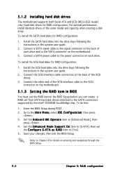
Save your changes, then exit the BIOS Setup. Refer to [Enhanced Mode], then press . 4. 5.1.2 Installing hard disk drives The motherboard supports both Serial ATA and SCSI (NCLV-DS2 model only) hard disk drives for RAID configuration: 1. Install the SATA hard disks into the drive bays following the instructions in the system user guide. 2. Set the O n b o a r d I D E O p e r a t e item to Chapter...
Save your changes, then exit the BIOS Setup. Refer to [Enhanced Mode], then press . 4. 5.1.2 Installing hard disk drives The motherboard supports both Serial ATA and SCSI (NCLV-DS2 model only) hard disk drives for RAID configuration: 1. Install the SATA hard disks into the drive bays following the instructions in the system user guide. 2. Set the O n b o a r d I D E O p e r a t e item to Chapter...

User Manual
Page 105
... from the support CD to a floppy disk before you install an operating system to the succeeding sections for details. Refer to the selected hard disk drive. For example, use the L S I L o g i c E m b e d d e d S A T A R A I S e l e c t ( T M ) U t i l i t y ! ASUS NCLV-D2 Series 5-3 5.1.4 RAID configuration utilities Depending on the RAID connectors that you use each RAID controller. Refer to use , you can create a RAID...
... from the support CD to a floppy disk before you install an operating system to the succeeding sections for details. Refer to the selected hard disk drive. For example, use the L S I L o g i c E m b e d d e d S A T A R A I S e l e c t ( T M ) U t i l i t y ! ASUS NCLV-D2 Series 5-3 5.1.4 RAID configuration utilities Depending on the RAID connectors that you use each RAID controller. Refer to use , you can create a RAID...

User Manual
Page 106
... the menu level. 5-4 Chapter 5: RAID configuration Refer to the Management Menu descriptions on the system after installing all the SATA hard disk drives. 2. Turn on the next page. At the bottom of the screen is enabled. 3. The LSI Logic Embedded SATA RAID ... Intel® 6300ESB Southbridge chip. The utility main window appears. During POST, the LSI Logic Embedded SATA RAID Setup Utility automatically detects the installed SATA hard disk drives and displays any existing RAID set (s) from the M a n a g e m e n t M e n u, then press . The keys on the legend box allow you...
... the menu level. 5-4 Chapter 5: RAID configuration Refer to the Management Menu descriptions on the system after installing all the SATA hard disk drives. 2. Turn on the next page. At the bottom of the screen is enabled. 3. The LSI Logic Embedded SATA RAID ... Intel® 6300ESB Southbridge chip. The utility main window appears. During POST, the LSI Logic Embedded SATA RAID Setup Utility automatically detects the installed SATA hard disk drives and displays any existing RAID set (s) from the M a n a g e m e n t M e n u, then press . The keys on the legend box allow you...

User Manual
Page 108
When selected, the drive indicator changes from R E A D Y to the SATA ports. 3. The A R R A Y S E L E C T I O N M E N U displays the available drives connected to ONLIN A[X]-[Y], where X is the array number, and Y is the drive number. Select all the drives required for the RAID set , then press . The configurable array appears on screen. 5-6 Chapter 5: RAID configuration The information of the selected hard disk drive displays at the bottom of the screen. 4. Select the drives you want to include in the RAID set , then press .
When selected, the drive indicator changes from R E A D Y to the SATA ports. 3. The A R R A Y S E L E C T I O N M E N U displays the available drives connected to ONLIN A[X]-[Y], where X is the array number, and Y is the drive number. Select all the drives required for the RAID set , then press . The configurable array appears on screen. 5-6 Chapter 5: RAID configuration The information of the selected hard disk drive displays at the bottom of the screen. 4. Select the drives you want to include in the RAID set , then press .

User Manual
Page 110
Select the RAID level from the L o g i c a l D r i v e menu, then press . 7. You need at least two identical hard disk drives when creating a RAID 1 set , proceed to step 10. 9. Key-in the stripe size, then press . 6. For multimedia computer systems used mainly for optimum performance. 5-8 Chapter 5: ...
Select the RAID level from the L o g i c a l D r i v e menu, then press . 7. You need at least two identical hard disk drives when creating a RAID 1 set , proceed to step 10. 9. Key-in the stripe size, then press . 6. For multimedia computer systems used mainly for optimum performance. 5-8 Chapter 5: ...

User Manual
Page 113
... R E A D Y to include in the RAID set, then press . ASUS NCLV-D2 Series 5-11 Adding a new RAID configuration To add a new RAID configuration: 1. From the Management Menu, highlight C o n f i g u r e, then press . 2. The information of the selected hard disk drive displays at the bottom of the screen. Select the drive(s) you want to ONLIN A[X]-[Y], where X is the array number...
... R E A D Y to include in the RAID set, then press . ASUS NCLV-D2 Series 5-11 Adding a new RAID configuration To add a new RAID configuration: 1. From the Management Menu, highlight C o n f i g u r e, then press . 2. The information of the selected hard disk drive displays at the bottom of the screen. Select the drive(s) you want to ONLIN A[X]-[Y], where X is the array number...

User Manual
Page 121
The P H Y S I C A L D R I V E S S E L E C T I O N M E N U displays the available drives connected to rebuild, then press . 5.2.4 Rebuilding failed drives You can manually rebuild failed hard disk drives using the R e b u i l d command in the Management Menu. To rebuild a failed hard disk drive: 1. ASUS NCLV-D2 Series 5-19 From the Management Menu, highlight R e b u i l d, then press . 2. Select the drive you want to the SATA ports.
The P H Y S I C A L D R I V E S S E L E C T I O N M E N U displays the available drives connected to rebuild, then press . 5.2.4 Rebuilding failed drives You can manually rebuild failed hard disk drives using the R e b u i l d command in the Management Menu. To rebuild a failed hard disk drive: 1. ASUS NCLV-D2 Series 5-19 From the Management Menu, highlight R e b u i l d, then press . 2. Select the drive you want to the SATA ports.

User Manual
Page 129
... installed SCSI hard disk drives and displays any existing RAID set (s) from SCSI hard disk drives connected to enter the utility. 3. Press + to the SCSI connector supported by the embedded Adaptec® SCSI controller. Select the SCSI channel, then press . ASUS NCLV-D2 Series 5-27... To enter the Adaptec SCSISelect(TM) Utility: 1. Turn on the system after installing all the SCSI hard disk drives. 2. The utility auto-detects the available SCSI channels.
... installed SCSI hard disk drives and displays any existing RAID set (s) from SCSI hard disk drives connected to enter the utility. 3. Press + to the SCSI connector supported by the embedded Adaptec® SCSI controller. Select the SCSI channel, then press . ASUS NCLV-D2 Series 5-27... To enter the Adaptec SCSISelect(TM) Utility: 1. Turn on the system after installing all the SCSI hard disk drives. 2. The utility auto-detects the available SCSI channels.

User Manual
Page 132
... for the selected RAID type. 5-30 Chapter 5: RAID configuration Use the S C S I D T y p e menu, then press . The utility displays the installed SCSI hard disk drives status and menu options. Press . Refer to the S t r i p i n g R e q u i r e m e n t s note at the bottom of the screen to clear the RAID configuration on the HDD(s). 3. Select R A I D - 0 ( H i g h P e r f o r m a n c e , N o F a u l t T o l e r a n c e ) from ...
... for the selected RAID type. 5-30 Chapter 5: RAID configuration Use the S C S I D T y p e menu, then press . The utility displays the installed SCSI hard disk drives status and menu options. Press . Refer to the S t r i p i n g R e q u i r e m e n t s note at the bottom of the screen to clear the RAID configuration on the HDD(s). 3. Select R A I D - 0 ( H i g h P e r f o r m a n c e , N o F a u l t T o l e r a n c e ) from ...

User Manual
Page 134
8. The screen displays the information on the created RAID set . 10. Make sure to create the RAID 0 set . When prompted to backup all data from the menu, then press . 9. The utility erases all important data before creating a RAID set , select , then press . Press to make the array bootable, select Y e s from the selected hard disk drives. A B u i l d C o m p l e t e message appears to indicate that you want to exit the utility. 5-32 Chapter 5: RAID configuration If you have successfully created the RAID 0 set .
8. The screen displays the information on the created RAID set . 10. Make sure to create the RAID 0 set . When prompted to backup all data from the menu, then press . 9. The utility erases all important data before creating a RAID set , select , then press . Press to make the array bootable, select Y e s from the selected hard disk drives. A B u i l d C o m p l e t e message appears to indicate that you want to exit the utility. 5-32 Chapter 5: RAID configuration If you have successfully created the RAID 0 set .