
User Manual
Page 4
... off the computer 3-2 3.2.1 Using the OS shut down function 3-2 3.2.2 Using the dual function power switch 3-2 Chapter 4: BIOS setup 4.1 Managing and updating your BIOS 4-1 4.1.1 Creating a bootable floppy disk 4-1 4.1.2 AFUDOS utility 4-2 4.1.3 ASUS CrashFree BIOS 2 utility 4-5 4.1.4 ASUS Update utility 4-7 4.2 BIOS setup program 4-10 4.2.1 BIOS menu screen 4-11 4.2.2 Menu bar 4-11 4.2.3 Navigation keys 4-11 4.2.4 Menu items 4-12 4.2.5 Sub-menu items 4-12...
... off the computer 3-2 3.2.1 Using the OS shut down function 3-2 3.2.2 Using the dual function power switch 3-2 Chapter 4: BIOS setup 4.1 Managing and updating your BIOS 4-1 4.1.1 Creating a bootable floppy disk 4-1 4.1.2 AFUDOS utility 4-2 4.1.3 ASUS CrashFree BIOS 2 utility 4-5 4.1.4 ASUS Update utility 4-7 4.2 BIOS setup program 4-10 4.2.1 BIOS menu screen 4-11 4.2.2 Menu bar 4-11 4.2.3 Navigation keys 4-11 4.2.4 Menu items 4-12 4.2.5 Sub-menu items 4-12...
User Manual
Page 5
... Setting up RAID 5-1 5.1.1 RAID definitions 5-1 5.1.2 Installing hard disk drives 5-2 5.1.3 Setting the RAID item in BIOS 5-2 5.1.4 RAID configuration utilities 5-3 5.2 LSI Logic Embedded SATA RAID Setup Utility 5-4 5.2.1 Creating a RAID set 5-5 5.2.2 Adding or viewing a RAID configuration 5-11 5.2.3 Initializing ...5.4.10 Verifying a RAID set hard disk drive 5-45 5.4.11 Making a RAID set bootable 5-46 5.5 Adaptec® RAID Configuration Utility (NCLV-D2/SATA model only 5-48 5.5.1 Configuring the hard disk drive(s 5-49 5.5.2 Creating a RAID 0 set (Striped 5-50 5.5.3 Creating a RAID ...
... Setting up RAID 5-1 5.1.1 RAID definitions 5-1 5.1.2 Installing hard disk drives 5-2 5.1.3 Setting the RAID item in BIOS 5-2 5.1.4 RAID configuration utilities 5-3 5.2 LSI Logic Embedded SATA RAID Setup Utility 5-4 5.2.1 Creating a RAID set 5-5 5.2.2 Adding or viewing a RAID configuration 5-11 5.2.3 Initializing ...5.4.10 Verifying a RAID set hard disk drive 5-45 5.4.11 Making a RAID set bootable 5-46 5.5 Adaptec® RAID Configuration Utility (NCLV-D2/SATA model only 5-48 5.5.1 Configuring the hard disk drive(s 5-49 5.5.2 Creating a RAID 0 set (Striped 5-50 5.5.3 Creating a RAID ...
User Manual
Page 9
...for installing the necessary drivers for product and software updates. 1. ix It includes description of the switches, jumpers, and connectors on ASUS hardware and software products. These documents are also provided. • Chapter 5: RAID configuration This chapter provides instructions for setting up...hardware setup procedures that you have been added by your dealer. Detailed descriptions of the BIOS parameters are not part of shutting down the system. • Chapter 4: BIOS setup This chapter tells how to perform when installing system components. Optional documentation Your ...
...for installing the necessary drivers for product and software updates. 1. ix It includes description of the switches, jumpers, and connectors on ASUS hardware and software products. These documents are also provided. • Chapter 5: RAID configuration This chapter provides instructions for setting up...hardware setup procedures that you have been added by your dealer. Detailed descriptions of the BIOS parameters are not part of shutting down the system. • Chapter 4: BIOS setup This chapter tells how to perform when installing system components. Optional documentation Your ...
User Manual
Page 12
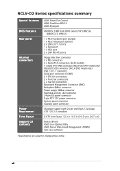
... contents ASUS Smart Fan Control ASUS CrashFree BIOS 2 ASUS MyLogo2 AMI BIOS, 8 MB Flash ROM, Green, PnP, DMI2.0a, SMBIOS 2.3, WfM2.0 1 x PS/2 keyboard port (purple) 1 x PS/2 mouse port (green) 2 x USB 2.0/1.1 ports 1 x Serial port 1 x VGA port 2 x LAN (RJ-45) ports Floppy disk drive connector 2 x IDE connectors 2 x Serial ATA connectors (both models) 4 x Serial ATA RAID connectors (NCLV-D2/SATA model...
... contents ASUS Smart Fan Control ASUS CrashFree BIOS 2 ASUS MyLogo2 AMI BIOS, 8 MB Flash ROM, Green, PnP, DMI2.0a, SMBIOS 2.3, WfM2.0 1 x PS/2 keyboard port (purple) 1 x PS/2 mouse port (green) 2 x USB 2.0/1.1 ports 1 x Serial port 1 x VGA port 2 x LAN (RJ-45) ports Floppy disk drive connector 2 x IDE connectors 2 x Serial ATA connectors (both models) 4 x Serial ATA RAID connectors (NCLV-D2/SATA model...
User Manual
Page 18
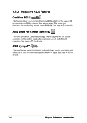
...allows you to restore the original BIOS data from the support CD in case when the BIOS codes and data are corrupted. See page 4-36 for details. See page 4-5 for details. 1-4 Chapter 1: Product introduction ASUS Smart Fan Control technology The ASUS Smart Fan Control technology smartly adjusts... the fan speeds according to the system loading to buy a replacement ROM chip. See page 4-28 for details. 1.3.2 Innovative ASUS features CrashFree BIOS 2 This feature allows you to personalize and add style to your system with customizable boot logos. This protection eliminates the need ...
...allows you to restore the original BIOS data from the support CD in case when the BIOS codes and data are corrupted. See page 4-36 for details. See page 4-5 for details. 1-4 Chapter 1: Product introduction ASUS Smart Fan Control technology The ASUS Smart Fan Control technology smartly adjusts... the fan speeds according to the system loading to buy a replacement ROM chip. See page 4-28 for details. 1.3.2 Innovative ASUS features CrashFree BIOS 2 This feature allows you to personalize and add style to your system with customizable boot logos. This protection eliminates the need ...

User Manual
Page 28
... setting (3-pin SCSI_EN1) 9. Adaptec 8130 LED setting (3-pin LED1) 11. CPU fan pin selection (3-pin FM_CPU1, FM_CPU2) 3. Force BIOS recovery setting (3-pin RECOVERY1) Rear panel connectors 1. USB device wake-up (3-pin USBPW12, USBPW34) 4. SATA controller setting (3-pin SATA_EN1) 10. Keyboard power (3-pin KBPWR1) 5. PS/2 keyboard port (purple) 3. VGA port 6. PS/2 mouse port...
... setting (3-pin SCSI_EN1) 9. Adaptec 8130 LED setting (3-pin LED1) 11. CPU fan pin selection (3-pin FM_CPU1, FM_CPU2) 3. Force BIOS recovery setting (3-pin RECOVERY1) Rear panel connectors 1. USB device wake-up (3-pin USBPW12, USBPW34) 4. SATA controller setting (3-pin SATA_EN1) 10. Keyboard power (3-pin KBPWR1) 5. PS/2 keyboard port (purple) 3. VGA port 6. PS/2 mouse port...
User Manual
Page 37
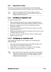
... ensure that the drivers support "Share IRQ" or that they support. Refer to the card. ASUS NCLV-D2 Series 2-17 Remove the system unit cover (if your motherboard is completely seated on BIOS setup. 2. Make sure to unplug the power cord before adding or removing expansion cards. See ...Chapter 4 for the expansion card. When using PCI cards on the system and change the necessary BIOS settings, if any. Align the card connector with the screw you physical injury and damage motherboard components. 2.5.1 Installing an expansion card ...
... ensure that the drivers support "Share IRQ" or that they support. Refer to the card. ASUS NCLV-D2 Series 2-17 Remove the system unit cover (if your motherboard is completely seated on BIOS setup. 2. Make sure to unplug the power cord before adding or removing expansion cards. See ...Chapter 4 for the expansion card. When using PCI cards on the system and change the necessary BIOS settings, if any. Align the card connector with the screw you physical injury and damage motherboard components. 2.5.1 Installing an expansion card ...

User Manual
Page 40
...about 5~10 seconds, then move the cap back to clear the Real Time Clock (RTC) RAM in certain models. 1. CLRTC1 21 32 Normal (Default) NCLV-D2 Series Clear RTC RAM Clear CMOS 2-20 Chapter 2: Hardware information 2.6 Jumpers The grayed out components in the illustrations may not be present in CMOS. Hold... down the key during the boot process and enter BIOS setup to pins 2-3. Keep the cap on CLRTC jumper default position. Turn OFF the computer and unplug the power cord. 2. Removing the cap...
...about 5~10 seconds, then move the cap back to clear the Real Time Clock (RTC) RAM in certain models. 1. CLRTC1 21 32 Normal (Default) NCLV-D2 Series Clear RTC RAM Clear CMOS 2-20 Chapter 2: Hardware information 2.6 Jumpers The grayed out components in the illustrations may not be present in CMOS. Hold... down the key during the boot process and enter BIOS setup to pins 2-3. Keep the cap on CLRTC jumper default position. Turn OFF the computer and unplug the power cord. 2. Removing the cap...

User Manual
Page 42
Keyboard power (3-pin KBPWR1) This jumper allows you to activate the VGA feature. KBPWR1 12 23 +5V (Default) +5VSB NCLV-D2 Series Keyboard power setting 5 . Set to pins 1-2 to enable or disable the keyboard wake-up the computer when you to wake up feature. VGA ...controller setting (3-pin VGA_EN1) These jumpers allow you press a key on the +5VSB lead, and a corresponding setting in the BIOS. Set this jumper to pins 2-3 (+5VSB) to enable or disable the onboard ATI® RAGE-XL PCI VGA controller. This feature requires an ATX power...
Keyboard power (3-pin KBPWR1) This jumper allows you to activate the VGA feature. KBPWR1 12 23 +5V (Default) +5VSB NCLV-D2 Series Keyboard power setting 5 . Set to pins 1-2 to enable or disable the keyboard wake-up the computer when you to wake up feature. VGA ...controller setting (3-pin VGA_EN1) These jumpers allow you press a key on the +5VSB lead, and a corresponding setting in the BIOS. Set this jumper to pins 2-3 (+5VSB) to enable or disable the onboard ATI® RAGE-XL PCI VGA controller. This feature requires an ATX power...
User Manual
Page 45
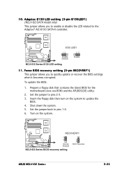
... RECOVERY1) This jumper allows you to enable or disable the LED related to quickly update or recover the BIOS settings when it becomes corrupted. RECOVERY1 1 2 Normal (Default) NCLV-D2 Series BIOS recovery setting 2 3 BIOS Recovery ASUS NCLV-D2 Series 2-25 Adaptec 8130 LED setting (3-pin 8130LED1) (NCLV-D2/SATA model only) This jumper allows you to the Adaptec® AIC-8130...
... RECOVERY1) This jumper allows you to enable or disable the LED related to quickly update or recover the BIOS settings when it becomes corrupted. RECOVERY1 1 2 Normal (Default) NCLV-D2 Series BIOS recovery setting 2 3 BIOS Recovery ASUS NCLV-D2 Series 2-25 Adaptec 8130 LED setting (3-pin 8130LED1) (NCLV-D2/SATA model only) This jumper allows you to the Adaptec® AIC-8130...
User Manual
Page 48
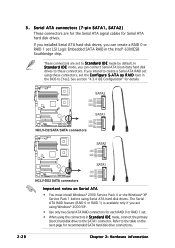
...connectors in Standard IDE mode, connect the primary (boot) hard disk drive to these connectors, set LSI Logic Embedded SATA RAID in the BIOS to the table on Serial ATA • You must install Windows® 2000 Service Pack 4 or the Windows... these connectors. SATA2 GND RSATA_TXP2 RSATA_TXN2 GND RSATA_RXP2 RSATA_RXN2 GND SATA1 NCLV-D2/SATA SATA connectors GND RSATA_TXP1 RSATA_TXN1 GND RSATA_RXP1 RSATA_RXN1 GND SATA2 GND RSATA_TXP2 RSATA_TXN2 GND RSATA_RXP2 RSATA_RXN2 GND NCLV-DS2 SATA connectors SATA1 GND RSATA_TXP1 RSATA_TXN1 GND RSATA_RXP1 RSATA_RXN1 GND Important notes on...
...connectors in Standard IDE mode, connect the primary (boot) hard disk drive to these connectors, set LSI Logic Embedded SATA RAID in the BIOS to the table on Serial ATA • You must install Windows® 2000 Service Pack 4 or the Windows... these connectors. SATA2 GND RSATA_TXP2 RSATA_TXN2 GND RSATA_RXP2 RSATA_RXN2 GND SATA1 NCLV-D2/SATA SATA connectors GND RSATA_TXP1 RSATA_TXN1 GND RSATA_RXP1 RSATA_RXN1 GND SATA2 GND RSATA_TXP2 RSATA_TXN2 GND RSATA_RXP2 RSATA_RXN2 GND NCLV-DS2 SATA connectors SATA1 GND RSATA_TXP1 RSATA_TXN1 GND RSATA_RXP1 RSATA_RXN1 GND Important notes on...
User Manual
Page 55
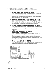
... connector is for the HDD Activity LED. Connect the chassis power LED cable to this connector. Connect the HDD Activity LED cable to this connector. ASUS NCLV-D2 Series 2-35 The IDE LED lights up when you to the HDD. • System warning speaker (Orange 4-pin SPEAKER) This 4-pin connector is for... power button turns the system on the system power, and blinks when the system is for system reboot without turning off mode depending on the BIOS settings. The system power LED lights up or flashes when data is read from or written to hear system beeps and warnings. • ATX...
... connector is for the HDD Activity LED. Connect the chassis power LED cable to this connector. Connect the HDD Activity LED cable to this connector. ASUS NCLV-D2 Series 2-35 The IDE LED lights up when you to the HDD. • System warning speaker (Orange 4-pin SPEAKER) This 4-pin connector is for... power button turns the system on the system power, and blinks when the system is for system reboot without turning off mode depending on the BIOS settings. The system power LED lights up or flashes when data is read from or written to hear system beeps and warnings. • ATX...

User Manual
Page 59
...for the first time 1. Connect the power cord to a power outlet that all the connections, replace the system case cover. 2. AMI BIOS beep codes Beep Description One beep Two continuous beeps followed by two short beeps Two continuous beeps followed by four short beeps Error Keyboard ...While the tests are off. 3. At power on the power, the system may light up when you do not see BIOS beep codes table below) or additional messages appear on the system front panel case lights up for assistance. Follow the instructions in the following order: a. ASUS NCLV-D2 Series 3-1
...for the first time 1. Connect the power cord to a power outlet that all the connections, replace the system case cover. 2. AMI BIOS beep codes Beep Description One beep Two continuous beeps followed by two short beeps Two continuous beeps followed by four short beeps Error Keyboard ...While the tests are off. 3. At power on the power, the system may light up when you do not see BIOS beep codes table below) or additional messages appear on the system front panel case lights up for assistance. Follow the instructions in the following order: a. ASUS NCLV-D2 Series 3-1

User Manual
Page 60
... sleep mode or to section "4.4.4 Power Configuration" in Chapter 4 for less than four seconds lets the system enter the soft-off mode regardless of the BIOS setting. The power supply should turn off after Windows® shuts down. Refer to soft-off mode, depending on the... BIOS setting. Make sure that the S h u t D o w n option button is ON, pressing the power switch for details. 3-2 Chapter 3: Powering up Click the T u r n O f f button to shut down the ...
... sleep mode or to section "4.4.4 Power Configuration" in Chapter 4 for less than four seconds lets the system enter the soft-off mode regardless of the BIOS setting. The power supply should turn off after Windows® shuts down. Refer to soft-off mode, depending on the... BIOS setting. Make sure that the S h u t D o w n option button is ON, pressing the power switch for details. 3-2 Chapter 3: Powering up Click the T u r n O f f button to shut down the ...

User Manual
Page 61
Detailed descriptions of the BIOS parameters are also provided. 4 BIOS setup This chapter tells how to change the system settings through the BIOS Setup menus.
Detailed descriptions of the BIOS parameters are also provided. 4 BIOS setup This chapter tells how to change the system settings through the BIOS Setup menus.

User Manual
Page 62
Chapter summary 4 4.1 Managing and updating your BIOS 4-1 4.2 BIOS setup program 4-10 4.3 Main menu 4-13 4.4 Advanced menu 4-18 4.5 Server menu 4-30 4.6 Security 4-32 4.7 Boot menu 4-35 ASUS NCLV-D2 Series
Chapter summary 4 4.1 Managing and updating your BIOS 4-1 4.2 BIOS setup program 4-10 4.3 Main menu 4-13 4.4 Advanced menu 4-18 4.5 Server menu 4-30 4.6 Security 4-32 4.7 Boot menu 4-35 ASUS NCLV-D2 Series

User Manual
Page 63
... disk to the corresponding sections for details on these utilities. b. Select the 3 1/2 Floppy Drive icon. Click F i l e from the format options field, then click S t a r t. 2. A F o r m a t 3 1 / 2 F l o p p y D i s k window appears. e. ASUS NCLV-D2 Series 4-1 A S U S C r a s h F r e e B I O S 2 (Updates the BIOS using the ASUS Update or AFUDOS utilities. 4.1.1 Creating a bootable floppy disk 1. D O S s t a r t u p d i s k from the menu, then select F o r m a t. Copy the original motherboard...
... disk to the corresponding sections for details on these utilities. b. Select the 3 1/2 Floppy Drive icon. Click F i l e from the format options field, then click S t a r t. 2. A F o r m a t 3 1 / 2 F l o p p y D i s k window appears. e. ASUS NCLV-D2 Series 4-1 A S U S C r a s h F r e e B I O S 2 (Updates the BIOS using the ASUS Update or AFUDOS utilities. 4.1.1 Creating a bootable floppy disk 1. D O S s t a r t u p d i s k from the menu, then select F o r m a t. Copy the original motherboard...

User Manual
Page 64
ok A:\> The utility returns to the bootable floppy disk you created earlier. 2. Version 1.19(ASUS V2.07(03.11.24BB)) Copyright (C) 2002 American Megatrends, Inc. A:\>afudos /oOLDBIOS1.rom Main filename Extension name 3. Reading flash ..... Copy the AFUDOS...motherboard support CD to the DOS prompt after copying the current BIOS file. 4-2 Chapter 4: BIOS setup The utility copies the current BIOS file to file...... Copying the current BIOS To copy the current BIOS file using a bootable floppy disk with the updated BIOS file. Press . All rights reserved. done Write to the ...
ok A:\> The utility returns to the bootable floppy disk you created earlier. 2. Version 1.19(ASUS V2.07(03.11.24BB)) Copyright (C) 2002 American Megatrends, Inc. A:\>afudos /oOLDBIOS1.rom Main filename Extension name 3. Reading flash ..... Copy the AFUDOS...motherboard support CD to the DOS prompt after copying the current BIOS file. 4-2 Chapter 4: BIOS setup The utility copies the current BIOS file to file...... Copying the current BIOS To copy the current BIOS file using a bootable floppy disk with the updated BIOS file. Press . All rights reserved. done Write to the ...

User Manual
Page 65
...iNCLVDS2.ROM AMI Firmware Update Utility - Erasing flash ...... ASUS NCLV-D2 Series 4-3 Updating the BIOS file To update the BIOS file using the AFUDOS utility: 1. Boot the system in DOS mode, then at the DOS prompt. 2. Version 1.19(ASUS V2.07(03.11.24BB)) Copyright (C) 2002 American Megatrends... depending on your motherboard model (e.g. The utility verifies the file and starts updating the BIOS. done Reading flash ...... Visit the ASUS website (www.asus.com) and download the latest BIOS file for the motherboard. All rights reserved. NCLVD2SATA.ROM or NCLVDS2.ROM) 4. Copy the...
...iNCLVDS2.ROM AMI Firmware Update Utility - Erasing flash ...... ASUS NCLV-D2 Series 4-3 Updating the BIOS file To update the BIOS file using the AFUDOS utility: 1. Boot the system in DOS mode, then at the DOS prompt. 2. Version 1.19(ASUS V2.07(03.11.24BB)) Copyright (C) 2002 American Megatrends... depending on your motherboard model (e.g. The utility verifies the file and starts updating the BIOS. done Reading flash ...... Visit the ASUS website (www.asus.com) and download the latest BIOS file for the motherboard. All rights reserved. NCLVD2SATA.ROM or NCLVDS2.ROM) 4. Copy the...

User Manual
Page 66
5. A:\>afudos /iNCLVDS2.ROM AMI Firmware Update Utility - Do not turn off power during flash BIOS Reading file ....... done Writing flash ...... Reboot the system from the hard disk drive. WARNING!! Erasing flash ...... done Please restart your computer A:\> 4-4 Chapter 4: BIOS setup Version 1.19(ASUS V2.07(03.11.24BB)) Copyright (C) 2002 American Megatrends, Inc. done Reading flash ...... done Advance Check ...... All rights reserved. done Verifying flash .... The utility returns to the DOS prompt after the BIOS update process is completed.
5. A:\>afudos /iNCLVDS2.ROM AMI Firmware Update Utility - Do not turn off power during flash BIOS Reading file ....... done Writing flash ...... Reboot the system from the hard disk drive. WARNING!! Erasing flash ...... done Please restart your computer A:\> 4-4 Chapter 4: BIOS setup Version 1.19(ASUS V2.07(03.11.24BB)) Copyright (C) 2002 American Megatrends, Inc. done Reading flash ...... done Advance Check ...... All rights reserved. done Verifying flash .... The utility returns to the DOS prompt after the BIOS update process is completed.
