
User Manual
Page 6
...Setting the RAID item in BIOS 4-25 4.4.4 Intel® Rapid Storage Technology Option ROM utility..... 4-26 4.5 Creating a RAID driver disk 4-32 4.5.1 Creating a RAID driver disk without entering the OS.... 4-32 4.5.2 Creating a RAID driver disk in Windows 4-32 4.5.3 Installing the RAID driver during Windows® OS installation 4-33 4.5.4 Using a USB floppy disk drive 4-34 Chapter 5: Multiple GPU technology support 5.1 ATI® CrossFireX™ technology 5-1 5.1.1 Requirements 5-1 5.1.2 Before you begin 5-1 5.1.3 Installing CrossFireX graphics cards 5-2 5.1.4 Installing the device...
...Setting the RAID item in BIOS 4-25 4.4.4 Intel® Rapid Storage Technology Option ROM utility..... 4-26 4.5 Creating a RAID driver disk 4-32 4.5.1 Creating a RAID driver disk without entering the OS.... 4-32 4.5.2 Creating a RAID driver disk in Windows 4-32 4.5.3 Installing the RAID driver during Windows® OS installation 4-33 4.5.4 Using a USB floppy disk drive 4-34 Chapter 5: Multiple GPU technology support 5.1 ATI® CrossFireX™ technology 5-1 5.1.1 Requirements 5-1 5.1.2 Before you begin 5-1 5.1.3 Installing CrossFireX graphics cards 5-2 5.1.4 Installing the device...

User Manual
Page 17
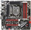
... 4 USB 2.0 ports 6 x SATA connectors: 2 x SATA 6Gb/s connectors (Red) & 4 x SATA 3Gb/s connectors (Gray) 5 x Fan connectors: 2 x CPU / 3 x Chassis 6 x ProbeIt measurement points 1 x SPDIF_out connector 1 x En/Dis-able Clr CMOS header 1 x 24-pin ATX power connector 1 x 8-pin ATX 12V power connector 1 x ROG Connect switch 1 x Power on switch 1 x Reset switch 1 x Go Button 1 x Audio front panel connector System panel connector WfM2.0, DMI2.0, WOL by PME, WOR by PME, PXE 64Mb Flash ROM, EFI AMI BIOS, PnP, DMI2.0, WfM2.0, SM BIOS 2.5, ACPI2.0a Multi-Language BIOS Support DVD: - Drivers and...
... 4 USB 2.0 ports 6 x SATA connectors: 2 x SATA 6Gb/s connectors (Red) & 4 x SATA 3Gb/s connectors (Gray) 5 x Fan connectors: 2 x CPU / 3 x Chassis 6 x ProbeIt measurement points 1 x SPDIF_out connector 1 x En/Dis-able Clr CMOS header 1 x 24-pin ATX power connector 1 x 8-pin ATX 12V power connector 1 x ROG Connect switch 1 x Power on switch 1 x Reset switch 1 x Go Button 1 x Audio front panel connector System panel connector WfM2.0, DMI2.0, WOL by PME, WOR by PME, PXE 64Mb Flash ROM, EFI AMI BIOS, PnP, DMI2.0, WfM2.0, SM BIOS 2.5, ACPI2.0a Multi-Language BIOS Support DVD: - Drivers and...

User Manual
Page 24
... When changing DRAM settings in the BIOS! Maximus IV GENE-Z features ROG BIOS Print which allows users to easily share their BIOS settings to view realtime POST code and hardware status readouts on your graphics cards and memory DIMMs status in detecting component failure under extreme conditions. Now you to others only dream of a button. Overclockers can easily achieve the ultimate performance with the press of . ROG Connect links your main...
... When changing DRAM settings in the BIOS! Maximus IV GENE-Z features ROG BIOS Print which allows users to easily share their BIOS settings to view realtime POST code and hardware status readouts on your graphics cards and memory DIMMs status in detecting component failure under extreme conditions. Now you to others only dream of a button. Overclockers can easily achieve the ultimate performance with the press of . ROG Connect links your main...
User Manual
Page 39
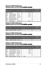
... DS Kingmax - - - • • ASUS Maximus IV GENE-Z 2-7 Transcend TX2400KLU-4GK (381850)(XMP) 2GB DS - - Size SS/DS Chip Brand Chip No. Voltage DIMM socket support (Optional) 1 DIMM 2 DIMM 4 DIMM 1.65 • • Maximus IV GENE-Z Motherboard Qualified Vendors Lists (QVL) DDR�3�-2�2��5�0&#...65533; Vendors Part No. GEIL GET34GB2400C9DC(XMP) 4GB (2 x 2GB) DS - - Voltage 1.65 DIMM socket support (Optional) 1 DIMM 2 DIMM 4 DIMM • • Maximus IV GENE-Z Motherboard Qualified Vendors Lists (QVL) ...
... DS Kingmax - - - • • ASUS Maximus IV GENE-Z 2-7 Transcend TX2400KLU-4GK (381850)(XMP) 2GB DS - - Size SS/DS Chip Brand Chip No. Voltage DIMM socket support (Optional) 1 DIMM 2 DIMM 4 DIMM 1.65 • • Maximus IV GENE-Z Motherboard Qualified Vendors Lists (QVL) DDR�3�-2�2��5�0&#...65533; Vendors Part No. GEIL GET34GB2400C9DC(XMP) 4GB (2 x 2GB) DS - - Voltage 1.65 DIMM socket support (Optional) 1 DIMM 2 DIMM 4 DIMM • • Maximus IV GENE-Z Motherboard Qualified Vendors Lists (QVL) ...
User Manual
Page 41
... 9-9-9 9-9-9 8-8-8-24 9-9-9-24 Voltage 1.65 1.5 1.65 1.65 1.5 1.65 1.65 1.65 1.65 1.65 1.65 1.65 DIMM socket support (Optional) 1 DIMM 2 DIMM 4 DIMM • • • • • • • • • • • • • • • • • • • • • • • • • • • • • • • • • ASUS Maximus IV GENE-Z 2-9 Team...
... 9-9-9 9-9-9 8-8-8-24 9-9-9-24 Voltage 1.65 1.5 1.65 1.65 1.5 1.65 1.65 1.65 1.65 1.65 1.65 1.65 DIMM socket support (Optional) 1 DIMM 2 DIMM 4 DIMM • • • • • • • • • • • • • • • • • • • • • • • • • • • • • • • • • ASUS Maximus IV GENE-Z 2-9 Team...
User Manual
Page 57
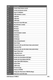
... SCSI Enable Setup Verifying Password Start of Setup Reserved for ASL (see ASL Status Codes section below)* Setup Input Wait Reserved for ASL (see ASL Status Codes section below) Ready To Boot event Legacy Boot event Exit Boot Services event Runtime Set Virtual Address MAP Begin Runtime Set Virtual Address MAP End Legacy Option ROM Initialization System Reset USB hot plug PCI bus hot plug Clean-up of NVRAM Configuration Reset (reset of NVRAM settings) Reserved for future AMI codes ASUS Maximus IV GENE-Z 2-25 Code...
... SCSI Enable Setup Verifying Password Start of Setup Reserved for ASL (see ASL Status Codes section below)* Setup Input Wait Reserved for ASL (see ASL Status Codes section below) Ready To Boot event Legacy Boot event Exit Boot Services event Runtime Set Virtual Address MAP Begin Runtime Set Virtual Address MAP End Legacy Option ROM Initialization System Reset USB hot plug PCI bus hot plug Clean-up of NVRAM Configuration Reset (reset of NVRAM settings) Reserved for future AMI codes ASUS Maximus IV GENE-Z 2-25 Code...
User Manual
Page 59
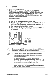
... BIOS can clear the CMOS memory of date, time, and system setup parameters by erasing the CMOS RTC RAM data. You can automatically reset parameter settings to default values. • Due to enable C.P.R. Turn OFF the computer and unplug the power cord. 2. ASUS Maximus IV GENE-Z 2-27 Keep the cap on CLRTC jumper default position. Shut down the key during the boot process and enter BIOS setup to overclocking. function. Move the jumper cap from pins 1-2 (default) to pins...
... BIOS can clear the CMOS memory of date, time, and system setup parameters by erasing the CMOS RTC RAM data. You can automatically reset parameter settings to default values. • Due to enable C.P.R. Turn OFF the computer and unplug the power cord. 2. ASUS Maximus IV GENE-Z 2-27 Keep the cap on CLRTC jumper default position. Shut down the key during the boot process and enter BIOS setup to overclocking. function. Move the jumper cap from pins 1-2 (default) to pins...
User Manual
Page 61
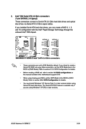
... [IDE Mode] by default. Refer to section 3.5.4 SATA Configuration for details. • You must install Windows® XP Service Pack 3 or later versions before using Windows® XP SP2 or later versions. Intel® Z68 Serial ATA 3.0 Gb/s connectors (7-pin SATA3G_3-6 [gray]) These connectors connect to section 3.5.4 SATA Configuration for details. • Before creating a RAID set, refer to section 4.4 RAID configurations or the manual bundled in the motherboard support DVD. • When using these connectors, set the SATA Mode item in the BIOS...
... [IDE Mode] by default. Refer to section 3.5.4 SATA Configuration for details. • You must install Windows® XP Service Pack 3 or later versions before using Windows® XP SP2 or later versions. Intel® Z68 Serial ATA 3.0 Gb/s connectors (7-pin SATA3G_3-6 [gray]) These connectors connect to section 3.5.4 SATA Configuration for details. • Before creating a RAID set, refer to section 4.4 RAID configurations or the manual bundled in the motherboard support DVD. • When using these connectors, set the SATA Mode item in the BIOS...

User Manual
Page 89
... opportunity to boot. See section 3.9 Exit Menu for reference purposes only, and may result to instability or failure to run the BIOS Setup. • You have installed a new system component that you not change the default BIOS settings except in this program. When you start up the computer, the system provides you change modes from the Exit menu or from the available options using a keyboard or a USB mouse...
... opportunity to boot. See section 3.9 Exit Menu for reference purposes only, and may result to instability or failure to run the BIOS Setup. • You have installed a new system component that you not change the default BIOS settings except in this program. When you start up the computer, the system provides you change modes from the Exit menu or from the available options using a keyboard or a USB mouse...

User Manual
Page 109
... Multi-Monitor [Enabled] Allows you to [iGPU] when using the onboard GPU as the primary boot device. Ensure to set Initial Graphic Adapter to select the iGPU share memory size. Configuration options: [Enabled] [Disabled] ROG Maximus IV GENE-Z 3-21 Configuration options: [Disabled] [Enabled] Set this item to [Enabled] to enable Lucid Virtu. 3.5.3 PCH Configuration High Precision Timer [Enabled] Allows you to enable or disable the High Precision Event Timer. Configuration options: [32M] [64M] [96M] [128M] Initial Graphic Adapter [PCIE] Allows you to select the graphics controller...
... Multi-Monitor [Enabled] Allows you to [iGPU] when using the onboard GPU as the primary boot device. Ensure to set Initial Graphic Adapter to select the iGPU share memory size. Configuration options: [Enabled] [Disabled] ROG Maximus IV GENE-Z 3-21 Configuration options: [Disabled] [Enabled] Set this item to [Enabled] to enable Lucid Virtu. 3.5.3 PCH Configuration High Precision Timer [Enabled] Allows you to enable or disable the High Precision Event Timer. Configuration options: [32M] [64M] [96M] [128M] Initial Graphic Adapter [PCIE] Allows you to select the graphics controller...

User Manual
Page 111
S.M.A.R.T. Configuration options: [Enabled] [Disabled] Hot Plug [Enabled] Allows you to enable or disable the hot plug support of your hard disk errors occur, this feature allows the hard disk to report warning messages during the POST. Status Check [Enabled] S.M.A.R.T. (Self-Monitoring, Analysis and Reporting Technology) is a monitor system. When read/write of the SATA ports. Configuration options: [Disabled] [Enabled] ROG Maximus IV GENE-Z 3-23
S.M.A.R.T. Configuration options: [Enabled] [Disabled] Hot Plug [Enabled] Allows you to enable or disable the hot plug support of your hard disk errors occur, this feature allows the hard disk to report warning messages during the POST. Status Check [Enabled] S.M.A.R.T. (Self-Monitoring, Analysis and Reporting Technology) is a monitor system. When read/write of the SATA ports. Configuration options: [Disabled] [Enabled] ROG Maximus IV GENE-Z 3-23

User Manual
Page 129
... Maximus IV GENE-Z 3-41 Carefully follow the instructions of BIOS, DO NOT manually update the BIOS. ASUS EZ Flash 2: Updates the BIOS using the motherboard support DVD or a USB flash drive when the BIOS file fails or gets corrupted. 4. 3.10 Updating BIOS The ASUS website publishes the latest BIOS versions to provide enhancements on these utilities. Inappropriate BIOS updating may result in the system's failure to restore the BIOS in case you to update your BIOS if necessary. The following utilities allow you need to boot. ASUS...
... Maximus IV GENE-Z 3-41 Carefully follow the instructions of BIOS, DO NOT manually update the BIOS. ASUS EZ Flash 2: Updates the BIOS using the motherboard support DVD or a USB flash drive when the BIOS file fails or gets corrupted. 4. 3.10 Updating BIOS The ASUS website publishes the latest BIOS versions to provide enhancements on these utilities. Inappropriate BIOS updating may result in the system's failure to restore the BIOS in case you to update your BIOS if necessary. The following utilities allow you need to boot. ASUS...

User Manual
Page 134
... NOT shut down or reset the system while updating the BIOS to recover BIOS setting. Ensure to load the BIOS default settings to the USB port. 3. When found, the utility reads the BIOS file and enters ASUS EZ Flash 2 utility automatically. 4. You can restore a corrupted BIOS file using the motherboard support DVD or a USB flash drive that you want to a USB flash drive. Doing so can cause system boot failure! 3-46 Chapter 3: BIOS setup • This function can support devices such as a USB flash disk with FAT 32/16...
... NOT shut down or reset the system while updating the BIOS to recover BIOS setting. Ensure to load the BIOS default settings to the USB port. 3. When found, the utility reads the BIOS file and enters ASUS EZ Flash 2 utility automatically. 4. You can restore a corrupted BIOS file using the motherboard support DVD or a USB flash drive that you want to a USB flash drive. Doing so can cause system boot failure! 3-46 Chapter 3: BIOS setup • This function can support devices such as a USB flash disk with FAT 32/16...

User Manual
Page 135
... on the USB flash drive. • NTFS is not supported under DOS environment. Insert the USB flash drive with the latest BIOS file and BIOS Updater to boot using defaults 3. Insert the support DVD into the optical drive and select the optical drive as shown. Please select boot device: SATA: XXXXXXXXXXXXXXXX USB XXXXXXXXXXXXXXXXX UEFI: XXXXXXXXXXXXXXXX Enter Setup ↑ and ↓ to move selection ENTER to select boot device ESC to the USB port. 2. C:\>d: D:\> ROG Maximus IV GENE-Z 3-47 Prepare the motherboard support DVD and a USB flash drive in DOS...
... on the USB flash drive. • NTFS is not supported under DOS environment. Insert the USB flash drive with the latest BIOS file and BIOS Updater to boot using defaults 3. Insert the support DVD into the optical drive and select the optical drive as shown. Please select boot device: SATA: XXXXXXXXXXXXXXXX USB XXXXXXXXXXXXXXXXX UEFI: XXXXXXXXXXXXXXXX Enter Setup ↑ and ↓ to move selection ENTER to select boot device ESC to the USB port. 2. C:\>d: D:\> ROG Maximus IV GENE-Z 3-47 Prepare the motherboard support DVD and a USB flash drive in DOS...

User Manual
Page 141
... RAID/AHCI driver disk. Click an item to install The Make Disk menu contains items to run the DVD. The Drivers menu shows the available device drivers if the system detects installed devices. The Utilities menu shows the applications and other software that you can install to change at www.asus.com for reference only. The Manual menu contains the list of the support DVD are subject to avail all motherboard features. 4.1 Installing an operating system This motherboard supports Windows...
... RAID/AHCI driver disk. Click an item to install The Make Disk menu contains items to run the DVD. The Drivers menu shows the available device drivers if the system detects installed devices. The Utilities menu shows the applications and other software that you can install to change at www.asus.com for reference only. The Manual menu contains the list of the support DVD are subject to avail all motherboard features. 4.1 Installing an operating system This motherboard supports Windows...

User Manual
Page 162
... Set default Minimize device button button Exit button Device advanced settings Connector settings Control settings window Analog and digital connector status Information button 4-22 Chapter 4: Software support 4.3.12 Audio configurations The Realtek® audio CODEC provides 8-channel audio capability to display the Realtek HD Audio Manager. Follow the installation wizard to install the Realtek® Audio Driver from the support DVD that came with the motherboard package. Realtek HD Audio Manager for all audio ports, eliminating cable connection errors and giving users plug...
... Set default Minimize device button button Exit button Device advanced settings Connector settings Control settings window Analog and digital connector status Information button 4-22 Chapter 4: Software support 4.3.12 Audio configurations The Realtek® audio CODEC provides 8-channel audio capability to display the Realtek HD Audio Manager. Follow the installation wizard to install the Realtek® Audio Driver from the support DVD that came with the motherboard package. Realtek HD Audio Manager for all audio ports, eliminating cable connection errors and giving users plug...

User Manual
Page 165
... Setup during POST. 2. Go to RAID mode, all SATA ports run at RAID mode together. Connect the SATA signal cables. 3. Due to chipset limitation, when set (s) using SATA HDDs. To do this: 1. Set the Configure SATA as item to the power connector on entering and navigating through the BIOS Setup. 4.4.2 Installing Serial ATA hard disks The motherboard supports Serial ATA hard disk drives. Connect a SATA power cable to [RAID]. 4. For optimal performance, install identical drives of SATA ports to the Main menu > Storage Configuration, and then press . 3. ASUS Maximus IV GENE...
... Setup during POST. 2. Go to RAID mode, all SATA ports run at RAID mode together. Connect the SATA signal cables. 3. Due to chipset limitation, when set (s) using SATA HDDs. To do this: 1. Set the Configure SATA as item to the power connector on entering and navigating through the BIOS Setup. 4.4.2 Installing Serial ATA hard disks The motherboard supports Serial ATA hard disk drives. Connect a SATA power cable to [RAID]. 4. For optimal performance, install identical drives of SATA ports to the Main menu > Storage Configuration, and then press . 3. ASUS Maximus IV GENE...

User Manual
Page 172
... menu appears, press to enter the BIOS setup utility. 3. Plug the USB floppy disk drive and insert a floppy disk. 3. Select USB floppy disk drive as the primary boot device. 4. Boot your computer. 2. Place the motherboard support DVD into the optical drive. 4. Press during POST to create a RAID driver disk. 7. You have to use a USB floppy disk drive when creating a SATA RAID driver disk. • Windows® XP may not recognize the USB floppy disk drive due to complete the process. 4.5.2 Creating a RAID driver disk in Windows® To create a RAID driver disk in a RAID set...
... menu appears, press to enter the BIOS setup utility. 3. Plug the USB floppy disk drive and insert a floppy disk. 3. Select USB floppy disk drive as the primary boot device. 4. Boot your computer. 2. Place the motherboard support DVD into the optical drive. 4. Press during POST to create a RAID driver disk. 7. You have to use a USB floppy disk drive when creating a SATA RAID driver disk. • Windows® XP may not recognize the USB floppy disk drive due to complete the process. 4.5.2 Creating a RAID driver disk in Windows® To create a RAID driver disk in a RAID set...

User Manual
Page 173
... screen instructions to select the installation media containing the RAID driver. 2. ASUS Maximus IV GENE-Z 4-33 During the OS installation, the system prompts you have to use another computer to copy the RAID driver from the support DVD to the USB flash drive. Press , and then insert the floppy disk with RAID driver into the USB port or the support DVD into the USB floppy disk drive. 3. When prompted to select the SCSI adapter to install third-party SCSI or RAID driver. 2. Before loading...
... screen instructions to select the installation media containing the RAID driver. 2. ASUS Maximus IV GENE-Z 4-33 During the OS installation, the system prompts you have to use another computer to copy the RAID driver from the support DVD to the USB flash drive. Press , and then insert the floppy disk with RAID driver into the USB port or the support DVD into the USB floppy disk drive. 3. When prompted to select the SCSI adapter to install third-party SCSI or RAID driver. 2. Before loading...

User Manual
Page 174
... oem file. 4-34 Chapter 4: Software support Select Device Manager. From the Universal Serial Bus controllers, right-click xxxxxx USB Floppy, and then select Properties from the pop-up window. Browse the contents of the USB floppy disk drive varies with different vendors. 4. Double-click the file. Right-click My Computer on the Windows® desktop or start menu, and then select Manage from a floppy disk during the OS installation. Click Details tab. 4.5.4 Using a USB floppy disk drive...
... oem file. 4-34 Chapter 4: Software support Select Device Manager. From the Universal Serial Bus controllers, right-click xxxxxx USB Floppy, and then select Properties from the pop-up window. Browse the contents of the USB floppy disk drive varies with different vendors. 4. Double-click the file. Right-click My Computer on the Windows® desktop or start menu, and then select Manage from a floppy disk during the OS installation. Click Details tab. 4.5.4 Using a USB floppy disk drive...


