
User Manual
Page 4
...panel connection 2-52 2.3.11 Audio I/O connections 2-53 2.4 Starting up for the first time 2-56 2.5 Turning off the computer 2-57 Chapter 3: BIOS setup 3.1 Knowing BIOS 3-1 3.2 BIOS setup program 3-1 3.2.1 EZ Mode 3-2 3.2.2 Advanced Mode 3-3 3.3 Extreme Tweaker menu 3-5 3.4 Main menu 3-14 3.4.1 System Language [English 3-14 3.4.2 System Date [Day xx/xx/xxxx 3-14 3.4.3 System Time [xx...Configuration 3-22 3.5.5 Onboard Devices Configuration 3-24 3.5.6 APM 3-26 3.5.7 iROG Configuration 3-27 3.5.8 ROG Connect 3-28 3.5.9 LED Control 3-28 3.6 Monitor menu 3-30 3.7 Boot menu 3-35 iv
...panel connection 2-52 2.3.11 Audio I/O connections 2-53 2.4 Starting up for the first time 2-56 2.5 Turning off the computer 2-57 Chapter 3: BIOS setup 3.1 Knowing BIOS 3-1 3.2 BIOS setup program 3-1 3.2.1 EZ Mode 3-2 3.2.2 Advanced Mode 3-3 3.3 Extreme Tweaker menu 3-5 3.4 Main menu 3-14 3.4.1 System Language [English 3-14 3.4.2 System Date [Day xx/xx/xxxx 3-14 3.4.3 System Time [xx...Configuration 3-22 3.5.5 Onboard Devices Configuration 3-24 3.5.6 APM 3-26 3.5.7 iROG Configuration 3-27 3.5.8 ROG Connect 3-28 3.5.9 LED Control 3-28 3.6 Monitor menu 3-30 3.7 Boot menu 3-35 iv

User Manual
Page 5
... 3-36 3.8.1 ASUS EZ Flash Utility 3-36 3.8.2 ASUS O.C. Profile 3-37 3.8.3 GO Button File 3-38 3.8.4 BIOS FlashBack 3-39 3.9 Exit menu 3-40 3.10 Updating BIOS 3-41 3.10.1 ASUS Update utility 3-42 3.10.2 ASUS EZ Flash Utility 3-45 3.10.3 ASUS CrashFree BIOS 3 utility 3-46 3.10.4 ASUS BIOS Updater 3-47 Chapter...15 4.4 RAID configurations 4-17 4.4.1 RAID definitions 4-17 4.4.2 Installing Serial ATA hard disks 4-18 4.4.3 Setting the RAID item in BIOS 4-18 4.4.4 Intel® Rapid Storage Technology Option ROM utility..... 4-18 4.4.5 Marvell RAID utility 4-22 4.5 Creating a RAID driver ...
... 3-36 3.8.1 ASUS EZ Flash Utility 3-36 3.8.2 ASUS O.C. Profile 3-37 3.8.3 GO Button File 3-38 3.8.4 BIOS FlashBack 3-39 3.9 Exit menu 3-40 3.10 Updating BIOS 3-41 3.10.1 ASUS Update utility 3-42 3.10.2 ASUS EZ Flash Utility 3-45 3.10.3 ASUS CrashFree BIOS 3 utility 3-46 3.10.4 ASUS BIOS Updater 3-47 Chapter...15 4.4 RAID configurations 4-17 4.4.1 RAID definitions 4-17 4.4.2 Installing Serial ATA hard disks 4-18 4.4.3 Setting the RAID item in BIOS 4-18 4.4.4 Intel® Rapid Storage Technology Option ROM utility..... 4-18 4.4.5 Marvell RAID utility 4-22 4.5 Creating a RAID driver ...
User Manual
Page 13
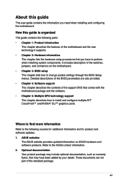
... chapter lists the hardware setup procedures that you need when installing and configuring the motherboard. ASUS websites The ASUS website provides updated information on the motherboard. • Chapter 3: BIOS setup This chapter tells how to the following parts: • Chapter 1: Product introduction This... chapter describes the features of the switches, jumpers, and connectors on ASUS hardware and software products. xiii Where to find more information Refer to change system settings through the BIOS Setup menus. These documents are also provided. • Chapter 4: Software ...
... chapter lists the hardware setup procedures that you need when installing and configuring the motherboard. ASUS websites The ASUS website provides updated information on the motherboard. • Chapter 3: BIOS setup This chapter tells how to the following parts: • Chapter 1: Product introduction This... chapter describes the features of the switches, jumpers, and connectors on ASUS hardware and software products. xiii Where to find more information Refer to change system settings through the BIOS Setup menus. These documents are also provided. • Chapter 4: Software ...
User Manual
Page 16
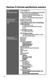
...;S�w�i�tc�h� - �D�e�b�u�g�L�E�D� - �Q�_�R�e�s�e�t EFI BIOS features - GPU DIMM Post - Maximus IV Extreme specifications summary LAN High Definition Audio Bluetooth Module Accessory Card USB ROG Exclusive Overclocking Features xvi 2 x Intel® Gigabit LAN RealteK ALC889 8-channel...
...;S�w�i�tc�h� - �D�e�b�u�g�L�E�D� - �Q�_�R�e�s�e�t EFI BIOS features - GPU DIMM Post - Maximus IV Extreme specifications summary LAN High Definition Audio Bluetooth Module Accessory Card USB ROG Exclusive Overclocking Features xvi 2 x Intel® Gigabit LAN RealteK ALC889 8-channel...
User Manual
Page 17
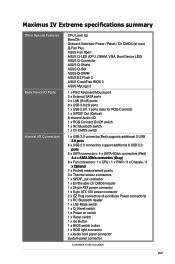
...ASUS Fan Xpert ASUS Q-LED (CPU, DRAM, VGA, Boot Device LED) ASUS Q-Connector ASUS Q-Shield ASUS Q-Slot ASUS Q-DIMM ASUS EZ Flash 2 ASUS CrashFree BIOS 3 ASUS MyLogo 2 1 x PS/2 Keyboard/Mouse port 2 x External SATA ports 2 x LAN (RJ45) ports 8 x USB 3.0/2.0 ports 1 x USB 2.0/1.1 ports (also for ROG Connect) 1 x S/PDIF Out (Optical) 8-channel Audio I /O Connectors CPU Level Up MemOK! Maximus IV Extreme... 1 x Power on switch 1 x Reset switch 1 x Go Button 1 x BIOS switch button 1 x ROG light connector 1 x Audio front panel connector System panel connector (continued on the next page) xvii
...ASUS Fan Xpert ASUS Q-LED (CPU, DRAM, VGA, Boot Device LED) ASUS Q-Connector ASUS Q-Shield ASUS Q-Slot ASUS Q-DIMM ASUS EZ Flash 2 ASUS CrashFree BIOS 3 ASUS MyLogo 2 1 x PS/2 Keyboard/Mouse port 2 x External SATA ports 2 x LAN (RJ45) ports 8 x USB 3.0/2.0 ports 1 x USB 2.0/1.1 ports (also for ROG Connect) 1 x S/PDIF Out (Optical) 8-channel Audio I /O Connectors CPU Level Up MemOK! Maximus IV Extreme... 1 x Power on switch 1 x Reset switch 1 x Go Button 1 x BIOS switch button 1 x ROG light connector 1 x Audio front panel connector System panel connector (continued on the next page) xvii
User Manual
Page 18
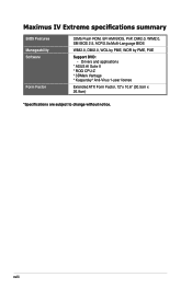
Drivers and applications * ASUS AI Suite II * ROG CPU-Z * 3DMark Vantage * Kaspersky® Anti-Virus 1-year license Extended ATX Form Factor, 12"x 10.6" (30.5cm x 26.9cm) *Specifications are subject to change without notice. Maximus IV Extreme specifications summary BIOS Features Manageability Software Form Factor 32Mb Flash ROM, EFI AMI BIOS, PnP, DMI2.0, WfM2.0, SM BIOS 2.5, ACPI2.0a Multi-Language BIOS WfM2.0, DMI2.0, WOL by PME, WOR by PME, PXE Support DVD: - xviii
Drivers and applications * ASUS AI Suite II * ROG CPU-Z * 3DMark Vantage * Kaspersky® Anti-Virus 1-year license Extended ATX Form Factor, 12"x 10.6" (30.5cm x 26.9cm) *Specifications are subject to change without notice. Maximus IV Extreme specifications summary BIOS Features Manageability Software Form Factor 32Mb Flash ROM, EFI AMI BIOS, PnP, DMI2.0, WfM2.0, SM BIOS 2.5, ACPI2.0a Multi-Language BIOS WfM2.0, DMI2.0, WOL by PME, WOR by PME, PXE Support DVD: - xviii
User Manual
Page 23
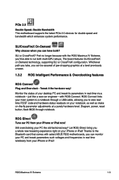
...? ROG Connect links your main system to a notebook through notebook. Diagram, power, reset button, flash BIOS through a USB cable, allowing you can monitor your PC and tweak parameters such voltages and frequencies in real...ASUS ROG motherboards, you a whole new tweaking experience right on -the-fly parameter adjustments at a level previously unseen. 1.3.2 ROG Intelligent Performance & Overclocking features ROG Connect Plug and Overclock - Still overclocking your desktop PC and tweak its parameters in real time wirelessly from your iPhone or iPad! ROG Maximus IV Extreme...
...? ROG Connect links your main system to a notebook through notebook. Diagram, power, reset button, flash BIOS through a USB cable, allowing you can monitor your PC and tweak parameters such voltages and frequencies in real...ASUS ROG motherboards, you a whole new tweaking experience right on -the-fly parameter adjustments at a level previously unseen. 1.3.2 ROG Intelligent Performance & Overclocking features ROG Connect Plug and Overclock - Still overclocking your desktop PC and tweak its parameters in real time wirelessly from your iPhone or iPad! ROG Maximus IV Extreme...
User Manual
Page 24
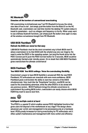
...1-4 Chapter 1: Product Introduction Very much like the "SaveGame" function, one can be used for the overclocking adventure, while the other BIOS is to be the most convenient way to be automatically flashed under standby power. Overclocker's prayer to use oridinary bluetooth functions, just...enthusiasts and it offers system maintenance and management with any stage! This design allows advanced user control and management to flash BIOS ever! No need to save two versions of conventional overclocking Still overclocking in old-fashioned way? RC Bluetooth Smashes all ...
...1-4 Chapter 1: Product Introduction Very much like the "SaveGame" function, one can be used for the overclocking adventure, while the other BIOS is to be the most convenient way to be automatically flashed under standby power. Overclocker's prayer to use oridinary bluetooth functions, just...enthusiasts and it offers system maintenance and management with any stage! This design allows advanced user control and management to flash BIOS ever! No need to save two versions of conventional overclocking Still overclocking in old-fashioned way? RC Bluetooth Smashes all ...
User Manual
Page 25
... with a unique design. ROG CPU-Z Whole new design of ROG CPU-Z to handle the demands of extreme performance, overvoltage adjustment is critical during overclocking. Maximus IV Extreme features ROG BIOS Print which allows users to easily share their BIOS settings to optimal performance. Use the whole new look of CPU-Z ROG CPU-Z is the one stop...
... with a unique design. ROG CPU-Z Whole new design of ROG CPU-Z to handle the demands of extreme performance, overvoltage adjustment is critical during overclocking. Maximus IV Extreme features ROG BIOS Print which allows users to easily share their BIOS settings to optimal performance. Use the whole new look of CPU-Z ROG CPU-Z is the one stop...
User Manual
Page 26
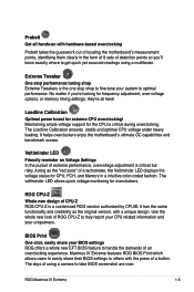
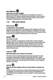
... Overclocking is provided to find out. Q-Fan Plus Optimized quietness and cooling for maximum performance achievement. 1-6 Chapter 1: Product Introduction Just enter the BIOS to detect temperature on up and running in order to monitor and save an overheating CPU. Any memory is the fastest memory booting solution today... instantly. Simply pick the processor you may activate Q-Fan function on any device. GPU.DIMM Post Easily check, just enter the BIOS! Worry no time. Overclcoking has never been this . When used to easily fix before attempting an overclock.
... Overclocking is provided to find out. Q-Fan Plus Optimized quietness and cooling for maximum performance achievement. 1-6 Chapter 1: Product Introduction Just enter the BIOS to detect temperature on up and running in order to monitor and save an overheating CPU. Any memory is the fastest memory booting solution today... instantly. Simply pick the processor you may activate Q-Fan function on any device. GPU.DIMM Post Easily check, just enter the BIOS! Worry no time. Overclcoking has never been this . When used to easily fix before attempting an overclock.
User Manual
Page 28
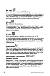
... benchmark from a USB flash disk before entering the OS. Profile Conveniently store or load multiple BIOS settings Freely share and distribute favorite overclocking settings The motherboard features the ASUS O.C. Q-Shield Easy and Comfortable Installations The specially designed ASUS Q-Shield does without preparing an additional floppy diskette or using an OSbased flash utility. making...
... benchmark from a USB flash disk before entering the OS. Profile Conveniently store or load multiple BIOS settings Freely share and distribute favorite overclocking settings The motherboard features the ASUS O.C. Q-Shield Easy and Comfortable Installations The specially designed ASUS Q-Shield does without preparing an additional floppy diskette or using an OSbased flash utility. making...
User Manual
Page 35
...1. Power connectors (24-pin EATXPWR, 8-pin EATX12V, 4-pin EZ_PLUG) 5. GO button 13. Front panel audio connector (10-1 pin AAFP) 21. Reset Switch 8. BIOS switch 18. USB78) 20. LN2 switch 11. Marvell® Serial ATA 6.0 Gb/s connectors (7-pin SATA6G_E1/E2 [red]) 14. Clear RTC RAM (3-pin CLRTC_SW) 17...Page 2-19 2-36 2-35 2-28 2-4 2-5 2-16 2-16 2-24 2-18 2-18 2-17 2-32 2-30 2-31 2-29 2-17 2-39 2-33 2-37 2-34 2-34 2-52 ASUS Maximus IV Extreme 2-3 Thermal sensor cable connectors (2-pin OPT_TEMP1-3) 4. Start Switch 9. Q-Reset Switch 2. Debug LEDs 10.
...1. Power connectors (24-pin EATXPWR, 8-pin EATX12V, 4-pin EZ_PLUG) 5. GO button 13. Front panel audio connector (10-1 pin AAFP) 21. Reset Switch 8. BIOS switch 18. USB78) 20. LN2 switch 11. Marvell® Serial ATA 6.0 Gb/s connectors (7-pin SATA6G_E1/E2 [red]) 14. Clear RTC RAM (3-pin CLRTC_SW) 17...Page 2-19 2-36 2-35 2-28 2-4 2-5 2-16 2-16 2-24 2-18 2-18 2-17 2-32 2-30 2-31 2-29 2-17 2-39 2-33 2-37 2-34 2-34 2-52 ASUS Maximus IV Extreme 2-3 Thermal sensor cable connectors (2-pin OPT_TEMP1-3) 4. Start Switch 9. Q-Reset Switch 2. Debug LEDs 10.
User Manual
Page 49
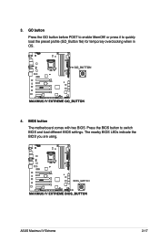
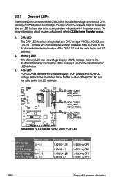
Press the BIOS button to enable MemOK! GO button Press the GO button before POST to switch BIOS and load different BIOS settings. or press it to quickly load the preset profile (GO_Button file) for temporary overclocking when in OS. 4. 3. ASUS Maximus IV Extreme 2-17 BIOS button The motherboard comes with two BIOS. The nearby BIOS LEDs indicate the BIOS you are using.
Press the BIOS button to enable MemOK! GO button Press the GO button before POST to switch BIOS and load different BIOS settings. or press it to quickly load the preset profile (GO_Button file) for temporary overclocking when in OS. 4. 3. ASUS Maximus IV Extreme 2-17 BIOS button The motherboard comes with two BIOS. The nearby BIOS LEDs indicate the BIOS you are using.
User Manual
Page 52
... the voltage conditions of the PCH LED and the table below for LED definition. For more information about voltage adjustment, refer to display in BIOS. Refer to the illustration below for the location of the CPU LED and the table below for power status. CPU LED The CPU LED...-2.1 Crazy (red) 1.55500-by CPU 1.20625-by CPU 1.25625-by CPU 2.10625-by CPU 2-20 Chapter 2: Hardware information you can select the voltage to 3.3 Extreme Tweaker menu. 1. Refer to the illustration below for the location of the memory LED and the table below for LED definition. 2. Memory LED The Memory...
... the voltage conditions of the PCH LED and the table below for LED definition. For more information about voltage adjustment, refer to display in BIOS. Refer to the illustration below for the location of the CPU LED and the table below for power status. CPU LED The CPU LED...-2.1 Crazy (red) 1.55500-by CPU 1.20625-by CPU 1.25625-by CPU 2.10625-by CPU 2-20 Chapter 2: Hardware information you can select the voltage to 3.3 Extreme Tweaker menu. 1. Refer to the illustration below for the location of the memory LED and the table below for LED definition. 2. Memory LED The Memory...

User Manual
Page 54
5. Press the BIOS button to switch between BIOS1 and BIOS2 and the LED lights up when the corresponding BIOS is enabled before POST. is in OS. 2-22 Chapter 2: Hardware information Lighting: Indicates that MemOK! GO LED Blinking: Indicates that the system loads the preset profile (GO_Button file) for temporary overclocking when in use. 6. BIOS LED The BIOS LEDs help indicate the BIOS activity.
5. Press the BIOS button to switch between BIOS1 and BIOS2 and the LED lights up when the corresponding BIOS is enabled before POST. is in OS. 2-22 Chapter 2: Hardware information Lighting: Indicates that MemOK! GO LED Blinking: Indicates that the system loads the preset profile (GO_Button file) for temporary overclocking when in use. 6. BIOS LED The BIOS LEDs help indicate the BIOS activity.

User Manual
Page 61
...memory of date, time, and system setup parameters by erasing the CMOS RTC RAM data. Shut down the key during the boot process and enter BIOS setup to enable C.P.R. Clear RTC RAM (3-pin CLRTC) This jumper allows you to pins 2-3. The onboard button cell battery powers the RAM data ... do not help, remove the onboard battery and move the cap back to clear the CMOS RTC RAM data. For system failure due to overclocking. ASUS Maximus IV Extreme 2-29 Plug the power cord and turn off is required to re-enter data. 2.2.8 Jumper 1. You must turn ON the computer. 4. You can...
...memory of date, time, and system setup parameters by erasing the CMOS RTC RAM data. Shut down the key during the boot process and enter BIOS setup to enable C.P.R. Clear RTC RAM (3-pin CLRTC) This jumper allows you to pins 2-3. The onboard button cell battery powers the RAM data ... do not help, remove the onboard battery and move the cap back to clear the CMOS RTC RAM data. For system failure due to overclocking. ASUS Maximus IV Extreme 2-29 Plug the power cord and turn off is required to re-enter data. 2.2.8 Jumper 1. You must turn ON the computer. 4. You can...
User Manual
Page 62
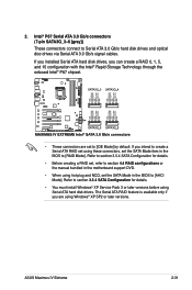
...Storage Technology through the onboard Intel® P67 chipset. • These connectors are using these connectors, set the SATA Mode item in the BIOS to create a Serial ATA RAID set using Windows® XP SP2 or later versions. 2-30 Chapter 2: Hardware information If you installed Serial... ATA hard disk drives, you are set the SATA Mode in the BIOS to [AHCI Mode] by default. Refer to section 3.5.4 SATA Configuration for details. • You must install Windows® XP Service Pack 3...
...Storage Technology through the onboard Intel® P67 chipset. • These connectors are using these connectors, set the SATA Mode item in the BIOS to create a Serial ATA RAID set using Windows® XP SP2 or later versions. 2-30 Chapter 2: Hardware information If you installed Serial... ATA hard disk drives, you are set the SATA Mode in the BIOS to [AHCI Mode] by default. Refer to section 3.5.4 SATA Configuration for details. • You must install Windows® XP Service Pack 3...
User Manual
Page 63
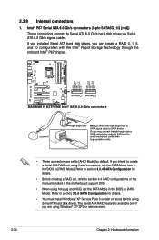
...install Windows® XP Service Pack 3 or later versions before using hot-plug and NCQ, set to [RAID Mode]. ASUS Maximus IV Extreme 2-31 The Serial ATA RAID feature is available only if you can create a RAID 0, 1, 5, and 10 configuration ... Serial ATA hard disk drives, you are set the SATA Mode in the BIOS to [IDE Mode] by default. If you intend to create a Serial ATA RAID set the SATA Mode... item in the BIOS to Serial ATA 3.0 Gb/s hard disk drives and optical disc drives via Serial ATA 3.0 Gb/s signal...
...install Windows® XP Service Pack 3 or later versions before using hot-plug and NCQ, set to [RAID Mode]. ASUS Maximus IV Extreme 2-31 The Serial ATA RAID feature is available only if you can create a RAID 0, 1, 5, and 10 configuration ... Serial ATA hard disk drives, you are set the SATA Mode in the BIOS to [IDE Mode] by default. If you intend to create a Serial ATA RAID set the SATA Mode... item in the BIOS to Serial ATA 3.0 Gb/s hard disk drives and optical disc drives via Serial ATA 3.0 Gb/s signal...

User Manual
Page 64
... created using the Marvell SATA controller, you have to create a RAID driver disk using hot-plug and NCQ, set the Marvell Controller item in the BIOS to section 3.5.6 Onboard Devices Configuration for data drives only. • You must install Windows® XP Service Pack 3 or later versions before using Serial ATA...
... created using the Marvell SATA controller, you have to create a RAID driver disk using hot-plug and NCQ, set the Marvell Controller item in the BIOS to section 3.5.6 Onboard Devices Configuration for data drives only. • You must install Windows® XP Service Pack 3 or later versions before using Serial ATA...

User Manual
Page 68
Enable OPT FAN1/2/3 overheat protection in BIOS if you want to these connectors. 2-36 Chapter 2: Hardware information The optional fan1/2/3 can work with the temperature sensors for temperature monitoring. Thermal sensor cable connectors (2-pin OPT_TEMP1/2/3) These connectors are for a better cooling effect. 8. Connect the thermal sensor cables to these connectors and place the other ends to the devices which you connect thermal sensor cables to monitor temperature.
Enable OPT FAN1/2/3 overheat protection in BIOS if you want to these connectors. 2-36 Chapter 2: Hardware information The optional fan1/2/3 can work with the temperature sensors for temperature monitoring. Thermal sensor cable connectors (2-pin OPT_TEMP1/2/3) These connectors are for a better cooling effect. 8. Connect the thermal sensor cables to these connectors and place the other ends to the devices which you connect thermal sensor cables to monitor temperature.


