User Manual
Page 32
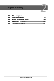
Chapter summary 2 2.1 Before you proceed 2-1 2.2 Motherboard overview 2-2 2.3 Building your computer system 2-40 2.4 Starting up for the first time 2-56 2.5 Turning off the computer 2-57 ASUS Maximus IV Extreme-Z
Chapter summary 2 2.1 Before you proceed 2-1 2.2 Motherboard overview 2-2 2.3 Building your computer system 2-40 2.4 Starting up for the first time 2-56 2.5 Turning off the computer 2-57 ASUS Maximus IV Extreme-Z
User Manual
Page 33
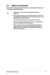
... wall socket before you proceed Take note of the following precautions before touching any motherboard settings. • Unplug the power cord from the power supply. ASUS Maximus IV Extreme-Z 2-1 2.1 Before you install motherboard components or change any component. • Before handling components, use a grounded wrist strap or touch a safely grounded object or a metal object...
... wall socket before you proceed Take note of the following precautions before touching any motherboard settings. • Unplug the power cord from the power supply. ASUS Maximus IV Extreme-Z 2-1 2.1 Before you install motherboard components or change any component. • Before handling components, use a grounded wrist strap or touch a safely grounded object or a metal object...
User Manual
Page 35
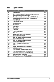
... Bluetooth connector (RC_BLUETOOTH) Page 2-19 2-35 2-36 2-38 2-4 2-5 2-16 2-16 2-24 2-18 2-18 2-17 2-32 2-30 2-31 2-29 2-17 2-39 2-33 2-37 2-34 2-34 2-52 ASUS Maximus IV Extreme-Z 2-3 Front panel audio connector (10-1 pin AAFP) 21.
... Bluetooth connector (RC_BLUETOOTH) Page 2-19 2-35 2-36 2-38 2-4 2-5 2-16 2-16 2-24 2-18 2-18 2-17 2-32 2-30 2-31 2-29 2-17 2-39 2-33 2-37 2-34 2-34 2-52 ASUS Maximus IV Extreme-Z 2-3 Front panel audio connector (10-1 pin AAFP) 21.
User Manual
Page 37
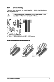
Recommended memory configurations ASUS Maximus IV Extreme-Z 2-5 2.2.4 System memory The motherboard comes with four Double Data Rate 3 (DDR3) Dual Inline Memory Modules (DIMM) slots. A DDR3 module is notched differently from a DDR or DDR2 module. DO NOT install a DDR or DDR2 memory module to the DDR3 slot.
Recommended memory configurations ASUS Maximus IV Extreme-Z 2-5 2.2.4 System memory The motherboard comes with four Double Data Rate 3 (DDR3) Dual Inline Memory Modules (DIMM) slots. A DDR3 module is notched differently from a DDR or DDR2 module. DO NOT install a DDR or DDR2 memory module to the DDR3 slot.
User Manual
Page 39
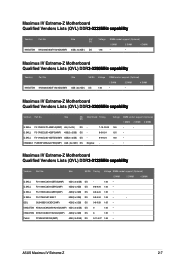
...support (Optional) 1 DIMM 2 DIMM 4 DIMM 1.65 • • 1.65 • 1.65 • - • Maximus IV Extreme-Z Motherboard Qualified Vendors Lists (QVL) DDR�3��-�2��1��3�3��M��H���z&#...) 4GB(2 x 2GB) DS 8 1.65 • Patriot PVV34G2133C9K(XMP) 4GB ( 2x 2GB ) DS 9-11-9-27 1.66 • ASUS Maximus IV Extreme-Z 2-7 KINGSTON KHX2250C9D3T1K2/4GX(XMP) Size SS/DS Voltage 4GB ( 2x 2GB ) DS 1.65 DIMM socket support (Optional) 1 DIMM 2 DIMM 4 DIMM •...
...support (Optional) 1 DIMM 2 DIMM 4 DIMM 1.65 • • 1.65 • 1.65 • - • Maximus IV Extreme-Z Motherboard Qualified Vendors Lists (QVL) DDR�3��-�2��1��3�3��M��H���z&#...) 4GB(2 x 2GB) DS 8 1.65 • Patriot PVV34G2133C9K(XMP) 4GB ( 2x 2GB ) DS 9-11-9-27 1.66 • ASUS Maximus IV Extreme-Z 2-7 KINGSTON KHX2250C9D3T1K2/4GX(XMP) Size SS/DS Voltage 4GB ( 2x 2GB ) DS 1.65 DIMM socket support (Optional) 1 DIMM 2 DIMM 4 DIMM •...

User Manual
Page 45
ASUS Maximus IV Extreme-Z 2-13 Hence, a total installed memory of 4GB capacity or more, Windows 32bit operating system may only recognize less than 3GB is recommended. • It is ...
ASUS Maximus IV Extreme-Z 2-13 Hence, a total installed memory of 4GB capacity or more, Windows 32bit operating system may only recognize less than 3GB is recommended. • It is ...
User Manual
Page 47
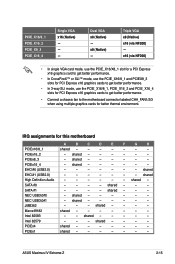
x16 (via NF200) - PCIEx16_4 - shared High Definition Audio - - - - - - SATA #1 - - - - shared - - - - - shared - - - - - - shared EHCI#1 (USB2.0) - - - - - - - shared - - - - - - shared - - - - - - shared - - - - PCIEx1 shared - - - - - - - ASUS Maximus IV Extreme-Z 2-15 x8 (Native) - IRQ assignments for better thermal environment. shared - - - - - - shared - - - shared - - - - PCIEx8_3 - EHCI#0 (USB2.0) - - - - - - - shared - Intel 82583 - - PCIEx4 shared - - - -...
x16 (via NF200) - PCIEx16_4 - shared High Definition Audio - - - - - - SATA #1 - - - - shared - - - - - shared - - - - - - shared EHCI#1 (USB2.0) - - - - - - - shared - - - - - - shared - - - - - - shared - - - - PCIEx1 shared - - - - - - - ASUS Maximus IV Extreme-Z 2-15 x8 (Native) - IRQ assignments for better thermal environment. shared - - - - - - shared - - - shared - - - - PCIEx8_3 - EHCI#0 (USB2.0) - - - - - - - shared - Intel 82583 - - PCIEx4 shared - - - -...
User Manual
Page 49
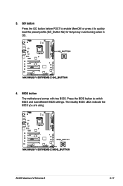
Press the BIOS button to quickly load the preset profile (GO_Button file) for temporary overclocking when in OS. 4. 3. or press it to switch BIOS and load different BIOS settings. The nearby BIOS LEDs indicate the BIOS you are using. BIOS button The motherboard comes with two BIOS. GO button Press the GO button before POST to enable MemOK! ASUS Maximus IV Extreme-Z 2-17
Press the BIOS button to quickly load the preset profile (GO_Button file) for temporary overclocking when in OS. 4. 3. or press it to switch BIOS and load different BIOS settings. The nearby BIOS LEDs indicate the BIOS you are using. BIOS button The motherboard comes with two BIOS. GO button Press the GO button before POST to enable MemOK! ASUS Maximus IV Extreme-Z 2-17

User Manual
Page 51
ASUS Maximus IV Extreme-Z 2-19 Q reset button When the LN2_Mode switch does not work and your CPU cannot resume function, press the Q reset button to temporarily stop the power supply to the CPU and help the CPU recover from a frozen condition. 7.
ASUS Maximus IV Extreme-Z 2-19 Q reset button When the LN2_Mode switch does not work and your CPU cannot resume function, press the Q reset button to temporarily stop the power supply to the CPU and help the CPU recover from a frozen condition. 7.
User Manual
Page 53
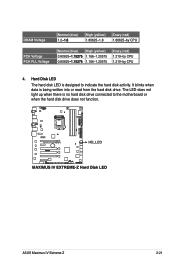
ASUS Maximus IV Extreme-Z 2-21 Hard Disk LED The hard disk LED is being written into or read from the hard disk drive. It blinks when data is designed ...
ASUS Maximus IV Extreme-Z 2-21 Hard Disk LED The hard disk LED is being written into or read from the hard disk drive. It blinks when data is designed ...
User Manual
Page 55
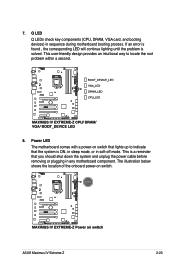
... the onboard power-on switch that you should shut down the system and unplug the power cable before removing or plugging in any motherboard component. ASUS Maximus IV Extreme-Z 2-23 Q LED Q LEDs check key components (CPU, DRAM, VGA card, and booting devices) in soft‑off mode. This user-friendly design provides an intuitional...
... the onboard power-on switch that you should shut down the system and unplug the power cable before removing or plugging in any motherboard component. ASUS Maximus IV Extreme-Z 2-23 Q LED Q LEDs check key components (CPU, DRAM, VGA card, and booting devices) in soft‑off mode. This user-friendly design provides an intuitional...

User Manual
Page 57
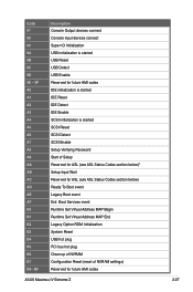
... S3 Resume is stared (S3 Resume PPI is started 3F - 4E OEM post memory initialization codes 4F DXE IPL is called by user (Forced recovery) ASUS Maximus IV Extreme-Z 2-25
... S3 Resume is stared (S3 Resume PPI is started 3F - 4E OEM post memory initialization codes 4F DXE IPL is called by user (Forced recovery) ASUS Maximus IV Extreme-Z 2-25
User Manual
Page 59
... Initialization System Reset USB hot plug PCI bus hot plug Clean-up of NVRAM Configuration Reset (reset of NVRAM settings) Reserved for future AMI codes ASUS Maximus IV Extreme-Z 2-27
... Initialization System Reset USB hot plug PCI bus hot plug Clean-up of NVRAM Configuration Reset (reset of NVRAM settings) Reserved for future AMI codes ASUS Maximus IV Extreme-Z 2-27

User Manual
Page 61
...) to overclocking. After the CMOS clearance, reinstall the battery. • You do not help, remove the onboard battery and move the cap back to enable C.P.R. ASUS Maximus IV Extreme-Z 2-29 You must turn ON the computer. 4. Keep the cap on the power supply or unplug and plug the power cord before rebooting the system...
...) to overclocking. After the CMOS clearance, reinstall the battery. • You do not help, remove the onboard battery and move the cap back to enable C.P.R. ASUS Maximus IV Extreme-Z 2-29 You must turn ON the computer. 4. Keep the cap on the power supply or unplug and plug the power cord before rebooting the system...
User Manual
Page 63
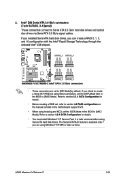
... Storage Technology through the onboard Intel® Z68 chipset. • These connectors are using these connectors, set using Windows® XP SP3 or later versions. ASUS Maximus IV Extreme-Z 2-31 If you installed Serial ATA hard disk drives, you are set to [IDE Mode] by default. If you intend to create a Serial ATA RAID...
... Storage Technology through the onboard Intel® Z68 chipset. • These connectors are using these connectors, set using Windows® XP SP3 or later versions. ASUS Maximus IV Extreme-Z 2-31 If you installed Serial ATA hard disk drives, you are set to [IDE Mode] by default. If you intend to create a Serial ATA RAID...
User Manual
Page 65
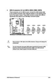
...! USB34; These USB connectors comply with USB 2.0 specification that supports up to the USB connectors. You can connect the front panel USB cable to the ASUS Q-Connector (USB, blue) first, and then install the Q-Connector (USB) to a slot opening at the back of the system chassis. Connect the USB module cable... connectors, then install the module to the USB connector onboard if your chassis supports front panel USB ports. USB78) These connectors are for USB 2.0 ports. 4. ASUS Maximus IV Extreme-Z 2-33 USB56;
...! USB34; These USB connectors comply with USB 2.0 specification that supports up to the USB connectors. You can connect the front panel USB cable to the ASUS Q-Connector (USB, blue) first, and then install the Q-Connector (USB) to a slot opening at the back of the system chassis. Connect the USB module cable... connectors, then install the module to the USB connector onboard if your chassis supports front panel USB ports. USB78) These connectors are for USB 2.0 ports. 4. ASUS Maximus IV Extreme-Z 2-33 USB56;
User Manual
Page 67
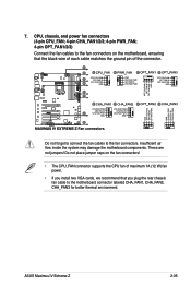
... fan cables to the motherboard connector labeled CHA_FAN1, CHA_FAN2, CHA_FAN3 for better thermal environment. Insufficient air flow inside the system may damage the motherboard components. ASUS Maximus IV Extreme-Z 2-35 These are not jumpers! CPU, chassis, and power fan connectors (4-pin CPU_FAN; 4-pin CHA_FAN1/2/3; 4-pin PWR_FAN; 4-pin OPT_FAN1/2/3) Connect the fan cables to the...
... fan cables to the motherboard connector labeled CHA_FAN1, CHA_FAN2, CHA_FAN3 for better thermal environment. Insufficient air flow inside the system may damage the motherboard components. ASUS Maximus IV Extreme-Z 2-35 These are not jumpers! CPU, chassis, and power fan connectors (4-pin CPU_FAN; 4-pin CHA_FAN1/2/3; 4-pin PWR_FAN; 4-pin OPT_FAN1/2/3) Connect the fan cables to the...
User Manual
Page 69
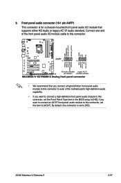
... the BIOS setup to [AC97]. if you want to connect an AC'97 front panel audio module to this connector, set the item to [HD]; ASUS Maximus IV Extreme-Z 2-37 9.
... the BIOS setup to [AC97]. if you want to connect an AC'97 front panel audio module to this connector, set the item to [HD]; ASUS Maximus IV Extreme-Z 2-37 9.

User Manual
Page 71
... or written to hear system beeps and warnings. • ATX power button/soft-off button (2-pin PWRSW) This connector is for the HDD Activity LED. ASUS Maximus IV Extreme-Z 2-39 Pressing the power button turns the system on or puts the system in sleep mode. • Hard disk drive activity LED (2-pin IDE_LED) This...
... or written to hear system beeps and warnings. • ATX power button/soft-off button (2-pin PWRSW) This connector is for the HDD Activity LED. ASUS Maximus IV Extreme-Z 2-39 Pressing the power button turns the system on or puts the system in sleep mode. • Hard disk drive activity LED (2-pin IDE_LED) This...

User Manual
Page 75
2.3.3 CPU heatsink and fan assembly installation Apply the Thermal Interface Material to the CPU heatsink and CPU before you install the heatsink and fan if necessary. To install the CPU heatsink and fan assembly 1 A 2 B B A 3 ASUS Maximus IV Extreme-Z 2-43
2.3.3 CPU heatsink and fan assembly installation Apply the Thermal Interface Material to the CPU heatsink and CPU before you install the heatsink and fan if necessary. To install the CPU heatsink and fan assembly 1 A 2 B B A 3 ASUS Maximus IV Extreme-Z 2-43


