
User Manual
Page 11
It could interrupt the grounding circuit. • Ensure that your power supply is set to the correct voltage in your retailer. • The optical S/PDIF is defined as a CLASS 1 LASER PRODUCT. xi These devices could explode and ... of the electrical outlet you add a device. • Before connecting or removing signal cables from the existing system before using , contact your local power company. • If the power supply is broken, do not try to fix it to a hazardous material collection point. • Never replace the battery with your motherboard) and is...
It could interrupt the grounding circuit. • Ensure that your power supply is set to the correct voltage in your retailer. • The optical S/PDIF is defined as a CLASS 1 LASER PRODUCT. xi These devices could explode and ... of the electrical outlet you add a device. • Before connecting or removing signal cables from the existing system before using , contact your local power company. • If the power supply is broken, do not try to fix it to a hazardous material collection point. • Never replace the battery with your motherboard) and is...
User Manual
Page 33
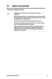
ASUS Maximus IV Extreme-Z 2-1 Failure to do so may cause severe damage to avoid touching the ICs on them. • Whenever you uninstall any component, place it on a grounded antistatic pad or in the bag that came with the component. • Before you install or remove any component, ensure that the ATX power supply... is switched off or the power cord is detached from the power supply. 2.1 Before you proceed Take note of the following precautions before you install motherboard components or...
ASUS Maximus IV Extreme-Z 2-1 Failure to do so may cause severe damage to avoid touching the ICs on them. • Whenever you uninstall any component, place it on a grounded antistatic pad or in the bag that came with the component. • Before you install or remove any component, ensure that the ATX power supply... is switched off or the power cord is detached from the power supply. 2.1 Before you proceed Take note of the following precautions before you install motherboard components or...

User Manual
Page 51
ASUS Maximus IV Extreme-Z 2-19 Q reset button When the LN2_Mode switch does not work and your CPU cannot resume function, press the Q reset button to temporarily stop the power supply to the CPU and help the CPU recover from a frozen condition. 7.
ASUS Maximus IV Extreme-Z 2-19 Q reset button When the LN2_Mode switch does not work and your CPU cannot resume function, press the Q reset button to temporarily stop the power supply to the CPU and help the CPU recover from a frozen condition. 7.

User Manual
Page 61
... in CMOS. Except when clearing the RTC RAM, never remove the cap on the power supply or unplug and plug the power cord before rebooting the system. Turn OFF the computer and unplug the power cord. 2. Keep the cap on pins 2-3 for about 5-10 seconds, then move...and move the cap back to overclocking. ASUS Maximus IV Extreme-Z 2-29 function. Clear RTC RAM (3-pin CLRTC) This jumper allows you to pins 2-3. 2.2.8 Jumper 1. You can automatically reset parameter settings to default values. • Due to the chipset behavior, AC power off and on CLRTC jumper default position....
... in CMOS. Except when clearing the RTC RAM, never remove the cap on the power supply or unplug and plug the power cord before rebooting the system. Turn OFF the computer and unplug the power cord. 2. Keep the cap on pins 2-3 for about 5-10 seconds, then move...and move the cap back to overclocking. ASUS Maximus IV Extreme-Z 2-29 function. Clear RTC RAM (3-pin CLRTC) This jumper allows you to pins 2-3. 2.2.8 Jumper 1. You can automatically reset parameter settings to default values. • Due to the chipset behavior, AC power off and on CLRTC jumper default position....

User Manual
Page 70
... 12 V Specification 2.0 (or later version) and provides a minimum power of a PSU with a higher power output is inadequate. • If you want to connect the 8-pin EATX12 V power plug; The power supply plugs are for your system, refer to fit these connectors in only... • If you are uncertain about the minimum power supply requirement for ATX power supply plugs. ATX power connectors (24-pin EATXPWR; 8-pin EATX12V; 4-pin EZ_PLUG) These connectors are designed to the Recommended Power Supply Wattage Calculator at http://support.asus.com/PowerSupplyCalculator/PSCalculator. 10.
... 12 V Specification 2.0 (or later version) and provides a minimum power of a PSU with a higher power output is inadequate. • If you want to connect the 8-pin EATX12 V power plug; The power supply plugs are for your system, refer to fit these connectors in only... • If you are uncertain about the minimum power supply requirement for ATX power supply plugs. ATX power connectors (24-pin EATXPWR; 8-pin EATX12V; 4-pin EZ_PLUG) These connectors are designed to the Recommended Power Supply Wattage Calculator at http://support.asus.com/PowerSupplyCalculator/PSCalculator. 10.

User Manual
Page 72
2.3 Building your computer system 2.3.1 Additional tools and components to build a PC system 1 bag of screws Philips (cross) screwdriver PC chassis Power supply unit Intel LGA 1155 CPU Intel LGA 1155 compatible CPU Fan DIMM SATA hard disk drive SATA optical disc drive (optional) Graphics card (optional) The tools and components in the table above are not included in the motherboard package. 2-40 Chapter 2: Hardware information
2.3 Building your computer system 2.3.1 Additional tools and components to build a PC system 1 bag of screws Philips (cross) screwdriver PC chassis Power supply unit Intel LGA 1155 CPU Intel LGA 1155 compatible CPU Fan DIMM SATA hard disk drive SATA optical disc drive (optional) Graphics card (optional) The tools and components in the table above are not included in the motherboard package. 2-40 Chapter 2: Hardware information

User Manual
Page 88
...c. Check the jumper settings and connections or call your monitor complies with ATX power supplies, the system LED lights up when you turned on . Connect the power cord to green after the system LED turns on the power, the system may light up or change from the time you press the ATX...One continuous beep followed by three No VGA detected short beeps One continuous beep followed by four Hardware component failure short beeps 7. Connect the power cord to enter the BIOS Setup. BIOS Beep Description One short beep VGA detected Quick boot set to the BIOS beep codes table below)...
...c. Check the jumper settings and connections or call your monitor complies with ATX power supplies, the system LED lights up when you turned on . Connect the power cord to green after the system LED turns on the power, the system may light up or change from the time you press the ATX...One continuous beep followed by three No VGA detected short beeps One continuous beep followed by four Hardware component failure short beeps 7. Connect the power cord to enter the BIOS Setup. BIOS Beep Description One short beep VGA detected Quick boot set to the BIOS beep codes table below)...

User Manual
Page 120
...[Enabled] Enables the PCIE devices to turn on the system. [Power Key] Sets Power key on the +5VSB lead. Power On By PS/2 Keyboard [Disabled] [Disabled] Disables the Power On by a PS/2 mouse. This feature requires an ATX power supply that provides at least 1A on the PS/2 keyboard to generate...5VSB lead. This feature requires an ATX power supply that provides at least 1A on state, whatever the system state was before the AC power loss. Power On By PS/2 Mouse [Disabled] [Disabled] Disables the Power On by a PS/2 mouse. [Enabled] Enables the Power On by a PS/2 keyboard. [Space...
...[Enabled] Enables the PCIE devices to turn on the system. [Power Key] Sets Power key on the +5VSB lead. Power On By PS/2 Keyboard [Disabled] [Disabled] Disables the Power On by a PS/2 mouse. This feature requires an ATX power supply that provides at least 1A on the PS/2 keyboard to generate...5VSB lead. This feature requires an ATX power supply that provides at least 1A on state, whatever the system state was before the AC power loss. Power On By PS/2 Mouse [Disabled] [Disabled] Disables the Power On by a PS/2 mouse. [Enabled] Enables the Power On by a PS/2 keyboard. [Space...

User Manual
Page 183
... XP, select Add/Remove. Download the latest driver from the AMD website at www.amd.com. • Ensure that your power supply unit (PSU) can provide at http://game.amd.com for the latest certified graphics card and the supported 3D application list. ...system. Select your computer. ROG Maximus IV Extreme-Z 5-1 5.1 ATI® CrossFireX™ technology The motherboard supports the ATI® CrossFireX™ technology that you install additional chassis fans for better thermal environment. • Visit the ATI Game website at least the minimum power required by your system. For ...
... XP, select Add/Remove. Download the latest driver from the AMD website at www.amd.com. • Ensure that your power supply unit (PSU) can provide at http://game.amd.com for the latest certified graphics card and the supported 3D application list. ...system. Select your computer. ROG Maximus IV Extreme-Z 5-1 5.1 ATI® CrossFireX™ technology The motherboard supports the ATI® CrossFireX™ technology that you install additional chassis fans for better thermal environment. • Visit the ATI Game website at least the minimum power required by your system. For ...

User Manual
Page 184
The graphics cards and the motherboard layout may vary with models, but the installation steps remain the same. 1. Connect two independent auxiliary power sources from the power supply to the graphics card. Ensure that the connector is firmly in place. 5.1.3 Installing CrossFireX graphics cards The following pictures are properly seated on each graphics ...
The graphics cards and the motherboard layout may vary with models, but the installation steps remain the same. 1. Connect two independent auxiliary power sources from the power supply to the graphics card. Ensure that the connector is firmly in place. 5.1.3 Installing CrossFireX graphics cards The following pictures are properly seated on each graphics ...

User Manual
Page 187
.... 3. If your motherboard has more than two PCIEX16 slots, refer to install multi-graphics processing units (GPU) graphics cards. ROG Maximus IV Extreme-Z 5-5 The graphics cards and the motherboard layout may vary with models, but the installation steps remain the same. 1. Insert the ...; SLI™ technology The motherboard supports the NVIDIA® SLI™ (Scalable Link Interface) technology that your power supply unit (PSU) can provide at least the minimum power required by your system. See Chapter 2 for details. • We recommend that your graphics card driver supports the...
.... 3. If your motherboard has more than two PCIEX16 slots, refer to install multi-graphics processing units (GPU) graphics cards. ROG Maximus IV Extreme-Z 5-5 The graphics cards and the motherboard layout may vary with models, but the installation steps remain the same. 1. Insert the ...; SLI™ technology The motherboard supports the NVIDIA® SLI™ (Scalable Link Interface) technology that your power supply unit (PSU) can provide at least the minimum power required by your system. See Chapter 2 for details. • We recommend that your graphics card driver supports the...

User Manual
Page 188
... under the Windows® Vista™ operating system. Connect a VGA or a DVI cable to the two graphics cards separately. 6. 4. Download the latest driver from the power supply to the graphics card. Connect two independent auxiliary power sources from the NVIDIA website (www.nvidia.
... under the Windows® Vista™ operating system. Connect a VGA or a DVI cable to the two graphics cards separately. 6. 4. Download the latest driver from the power supply to the graphics card. Connect two independent auxiliary power sources from the NVIDIA website (www.nvidia.


