M5A97 R2.0 User's Manual
Page 11
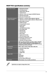
xi M5A97 R2.0 specifications summary Back Panel I/O ports Internal I /O Shield 1 x User Manual 1 x Support DVD Drivers ASUS Update ASUS utilities Anti-Virus software (OEM version) ATX form factor: 12 in x 9 in (30.5 cm x 22.9 cm) Specifications are subject to change without notice. button 1 x DirectKey button 1 x DRCT header 1 x System panel connector 1 x CPU fan connector (4-pin) 3 x Chassis fan connectors (3 x 4-pin) 1 x 24-pin EATX...
xi M5A97 R2.0 specifications summary Back Panel I/O ports Internal I /O Shield 1 x User Manual 1 x Support DVD Drivers ASUS Update ASUS utilities Anti-Virus software (OEM version) ATX form factor: 12 in x 9 in (30.5 cm x 22.9 cm) Specifications are subject to change without notice. button 1 x DirectKey button 1 x DRCT header 1 x System panel connector 1 x CPU fan connector (4-pin) 3 x Chassis fan connectors (3 x 4-pin) 1 x 24-pin EATX...

M5A97 R2.0 User's Manual
Page 20
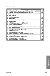
...M5A97 R2.0 PCIEX16_2 64Mb BIOS DirectKey ASM 1042 AMD® SB950 SATA6G_6 SATA6G_5 USB3_34 PCI1 SATA6G_2 SATA6G_4 ALC 887 SB_PWR PCI2 CLRTC DRCT SPDIF_OUT COM1 TPM USB1314 USB1112 USB910 FLBK_LED PANEL SATA6G_1 SATA6G_3 AAFP BIOS_FLBK 7 8 9 10 11 12 9 20 19 18 17 16 15 14 13 Refer to 1.2.9 Internal connectors... and 2.3.1 Rear I/O connection for more information about rear panel connectors and internal connectors. 1.2.2 Motherboard layout 1 2 3 1 4 22.9cm(9.0in) KBMS EATX12V EPU CHA_FAN2 ...
...M5A97 R2.0 PCIEX16_2 64Mb BIOS DirectKey ASM 1042 AMD® SB950 SATA6G_6 SATA6G_5 USB3_34 PCI1 SATA6G_2 SATA6G_4 ALC 887 SB_PWR PCI2 CLRTC DRCT SPDIF_OUT COM1 TPM USB1314 USB1112 USB910 FLBK_LED PANEL SATA6G_1 SATA6G_3 AAFP BIOS_FLBK 7 8 9 10 11 12 9 20 19 18 17 16 15 14 13 Refer to 1.2.9 Internal connectors... and 2.3.1 Rear I/O connection for more information about rear panel connectors and internal connectors. 1.2.2 Motherboard layout 1 2 3 1 4 22.9cm(9.0in) KBMS EATX12V EPU CHA_FAN2 ...
M5A97 R2.0 User's Manual
Page 21
... power LED (SB_PWR) 1-20 11. System panel connector (20-8 pin PANEL) 1-25 14. TPM header (20-1 pin TPM) 1-21 18. Front panel audio connector (10-1 pin AAFP) 1-26 19. MemOK! Clear RTC RAM (3-pin CLRTC) 1-19 12. SATA 6.0Gb/s connectors (7-pin SATA6G_1~6) 1-23 10. Digital audio connector (4-1 pin SPDIF_OUT) 1-24 Chapter 1 M5A97 R2.0 1-7 DirectKey button 1-16 9. DRCT header (2-pin...
... power LED (SB_PWR) 1-20 11. System panel connector (20-8 pin PANEL) 1-25 14. TPM header (20-1 pin TPM) 1-21 18. Front panel audio connector (10-1 pin AAFP) 1-26 19. MemOK! Clear RTC RAM (3-pin CLRTC) 1-19 12. SATA 6.0Gb/s connectors (7-pin SATA6G_1~6) 1-23 10. Digital audio connector (4-1 pin SPDIF_OUT) 1-24 Chapter 1 M5A97 R2.0 1-7 DirectKey button 1-16 9. DRCT header (2-pin...

M5A97 R2.0 User's Manual
Page 38
... for a serial (COM) port. Go to Start > Control Panel > Sounds and Audio Devices > Sound Playback to a slot opening at the back of Sound playback is for an additional Sony/Philips Digital Interface (S/PDIF) port. +5V SPDIFOUT GND Chapter 1 M5A97 R2.0 SPDIF_OUT M5A97 R2.0 Digital audio connector Ensure that the audio device of the system chassis. Serial...
... for a serial (COM) port. Go to Start > Control Panel > Sounds and Audio Devices > Sound Playback to a slot opening at the back of Sound playback is for an additional Sony/Philips Digital Interface (S/PDIF) port. +5V SPDIFOUT GND Chapter 1 M5A97 R2.0 SPDIF_OUT M5A97 R2.0 Digital audio connector Ensure that the audio device of the system chassis. Serial...

M5A97 R2.0 User's Manual
Page 39
... without turning off button (2-pin PWRSW) This connector is for the system power LED. PWR Ground Reset Ground M5A97 R2.0 IDE_LED PWRSW RESET * Requires an ATX power supply M5A97 R2.0 System panel connector • System power LED (2-pin PLED) This 2-pin connector is for the HDD Activity LED. The system... the system on the BIOS settings. The IDE LED lights up when you to this connector. PLED SPEAKER PLED+ PLED+5V Ground Ground Speaker PANEL PIN 1 IDE_LED+ IDE_LED- Chapter 1 M5A97 R2.0 1-25 Pressing the power switch for more than four seconds while the system is ON...
... without turning off button (2-pin PWRSW) This connector is for the system power LED. PWR Ground Reset Ground M5A97 R2.0 IDE_LED PWRSW RESET * Requires an ATX power supply M5A97 R2.0 System panel connector • System power LED (2-pin PLED) This 2-pin connector is for the HDD Activity LED. The system... the system on the BIOS settings. The IDE LED lights up when you to this connector. PLED SPEAKER PLED+ PLED+5V Ground Ground Speaker PANEL PIN 1 IDE_LED+ IDE_LED- Chapter 1 M5A97 R2.0 1-25 Pressing the power switch for more than four seconds while the system is ON...

M5A97 R2.0 User's Manual
Page 40
... of the chassis. USB 3.0 connector (20-1 pin USB3_34) This connector is for details. • The front panel audio I /O module that you connect a high-definition front panel audio module to this connector to avail of the motherboard high-definition audio capability. • If you can have a front panel USB 3.0 solution. USB3_34 M5A97 R2.0 M5A97 R2.0 USB3.0 Front panel connector The USB 3.0 module is...
... of the chassis. USB 3.0 connector (20-1 pin USB3_34) This connector is for details. • The front panel audio I /O module that you connect a high-definition front panel audio module to this connector to avail of the motherboard high-definition audio capability. • If you can have a front panel USB 3.0 solution. USB3_34 M5A97 R2.0 M5A97 R2.0 USB3.0 Front panel connector The USB 3.0 module is...

M5A97 R2.0 User's Manual
Page 55
... better performance for your USB 3.0 devices. • USB 2.0_1 port supports USB BIOS Flashback. Audio I /O connection Rear panel connectors 1. USB 2.0 ports (USB 2.0 port1 supports USB BIOS Flashback) 5. USB 3.0 ports 1 and 2 support ASUS USB 3.0 Boost UASP Mode. 7. LAN (RJ-45) port* 3. ASUS M5A97 R2.0 2-13 Chapter 2 PS/2 mouse port (green) 2. 2.3 Motherboard rear and audio connections 2.3.1 Rear I /O ports** 4.
... better performance for your USB 3.0 devices. • USB 2.0_1 port supports USB BIOS Flashback. Audio I /O connection Rear panel connectors 1. USB 2.0 ports (USB 2.0 port1 supports USB BIOS Flashback) 5. USB 3.0 ports 1 and 2 support ASUS USB 3.0 Boost UASP Mode. 7. LAN (RJ-45) port* 3. ASUS M5A97 R2.0 2-13 Chapter 2 PS/2 mouse port (green) 2. 2.3 Motherboard rear and audio connections 2.3.1 Rear I /O ports** 4.

M5A97 R2.0 User's Manual
Page 59
...the power cord to the power connector at the back of the BIOS setting. System power 6. If your retailer for the first time 1. Check the jumper settings and connections or call your monitor complies with ATX power supplies, the system LED lights up . Chapter 2 ASUS M5A97 R2.0 2-17 Connect the power cord ...setting. 2.4 Starting up or change from orange to green after the system LED turns on the chain) c. At power on the system front panel case lights up when you turned on the power, the system may light up for assistance. Press the power switch for less than four ...
...the power cord to the power connector at the back of the BIOS setting. System power 6. If your retailer for the first time 1. Check the jumper settings and connections or call your monitor complies with ATX power supplies, the system LED lights up . Chapter 2 ASUS M5A97 R2.0 2-17 Connect the power cord ...setting. 2.4 Starting up or change from orange to green after the system LED turns on the chain) c. At power on the system front panel case lights up when you turned on the power, the system may light up for assistance. Press the power switch for less than four ...

M5A97 R2.0 User's Manual
Page 79
...or modem card. This feature requires an ATX power supply that the front panel audio module supports. [HD] Sets the front panel audio connector (AAFP) mode to high definition audio. [AC97] Sets the front panel audio connector (AAFP) mode to legacy AC'97 SPDIF Out Type [SPDIF] [SPDIF]... front panel audio connector (AAFP) type to turn on the +5VSB lead. This feature requires an ATX power supply that provides at least 1A on the system. Configuration options: [Enabled] [Disabled] The following two items appear only when you to [Disabled]. Chapter 3 ASUS M5A97 R2.0 3-19...
...or modem card. This feature requires an ATX power supply that the front panel audio module supports. [HD] Sets the front panel audio connector (AAFP) mode to high definition audio. [AC97] Sets the front panel audio connector (AAFP) mode to legacy AC'97 SPDIF Out Type [SPDIF] [SPDIF]... front panel audio connector (AAFP) type to turn on the +5VSB lead. This feature requires an ATX power supply that provides at least 1A on the system. Configuration options: [Enabled] [Disabled] The following two items appear only when you to [Disabled]. Chapter 3 ASUS M5A97 R2.0 3-19...


