User Manual
Page 11
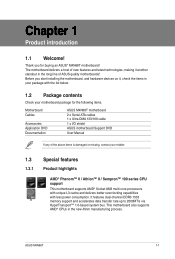
... contents Check your motherboard package for buying an ASUS® M4N68T motherboard! Before you for the following items. Motherboard Cables Accessories Application DVD Documentation ASUS M4N68T motherboard 2 x Serial ATA cables 1 x Ultra DMA 133/100 cable 1 x I/O shield ASUS motherboard Support DVD User Manual If any of ASUS quality motherboards! ASUS M4N68T 1-1 Thank you start installing the motherboard, and hardware...
... contents Check your motherboard package for buying an ASUS® M4N68T motherboard! Before you for the following items. Motherboard Cables Accessories Application DVD Documentation ASUS M4N68T motherboard 2 x Serial ATA cables 1 x Ultra DMA 133/100 cable 1 x I/O shield ASUS motherboard Support DVD User Manual If any of ASUS quality motherboards! ASUS M4N68T 1-1 Thank you start installing the motherboard, and hardware...
User Manual
Page 13
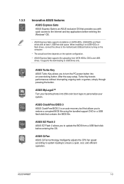
..., cool, and efficient operation. ASUS M4N68T 1-3 After the easy setup, Turbo Key boosts performances without interrupting ongoing work or games, simply through pressing the button. ASUS CrashFree BIOS 3 ASUS CrashFree BIOS 3 is an ASUS exclusive OS that contains the BIOS file. ASUS EZ Flash 2 ASUS EZ Flash 2 allows you to...Key allows you to turn the PC power button into 256-color boot logos to personalize your system. 1.3.2 Innovative ASUS features ASUS Express Gate ASUS Express Gate is an auto-recovery tool that allows you to restore a corrupted BIOS file using the bundled support...
..., cool, and efficient operation. ASUS M4N68T 1-3 After the easy setup, Turbo Key boosts performances without interrupting ongoing work or games, simply through pressing the button. ASUS CrashFree BIOS 3 ASUS CrashFree BIOS 3 is an ASUS exclusive OS that contains the BIOS file. ASUS EZ Flash 2 ASUS EZ Flash 2 allows you to...Key allows you to turn the PC power button into 256-color boot logos to personalize your system. 1.3.2 Innovative ASUS features ASUS Express Gate ASUS Express Gate is an auto-recovery tool that allows you to restore a corrupted BIOS file using the bundled support...
User Manual
Page 15
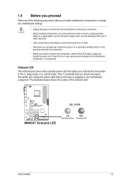
..., peripherals, or components. This is ON, in sleep mode, or in any component, switch off mode. 1.4 Before you proceed Take note of the onboard LED. M4N68T SB_PWR M4N68T Onboard LED ON OFF Standby Power Powered Off ASUS M4N68T 1-5
..., peripherals, or components. This is ON, in sleep mode, or in any component, switch off mode. 1.4 Before you proceed Take note of the onboard LED. M4N68T SB_PWR M4N68T Onboard LED ON OFF Standby Power Powered Off ASUS M4N68T 1-5
User Manual
Page 17
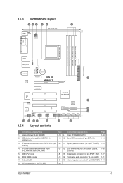
Serial ATA connectors (7-pin SATA1-4) 1-24 3. IDE connector (40-1 pin PRI_IDE) 1-23 ASUS M4N68T 1-7 CPU and chassis fan connectors (4-pin CPU_FAN and 3-pin CHA_FAN) 1-27 12. 1.5.3 Motherboard layout 123 45 6 20.8cm(8.2in) KBMS KBPWR ...DDR3 DIMM_B1 (64bit, 240-pin module) EATXPWR 30.5cm(12.0in) USBPW1-4 USB34 LAN1_USB12 CPU_FAN CHA_FAN AUDIO Lithium Cell CMOS Power PCIEX1_1 3 RTL 8211CL M4N68T PCIEX16 PCIEX1_2 PCI1 NVIDIA® MCP68 SE Super I/O PCI2 7 SPEAKER 8Mb BIOS VIA VT1708S PCI3 SB_PWR PRI_IDE 8 CLRTC PCI4 9 USBPW5-10 USB56 USB78...
Serial ATA connectors (7-pin SATA1-4) 1-24 3. IDE connector (40-1 pin PRI_IDE) 1-23 ASUS M4N68T 1-7 CPU and chassis fan connectors (4-pin CPU_FAN and 3-pin CHA_FAN) 1-27 12. 1.5.3 Motherboard layout 123 45 6 20.8cm(8.2in) KBMS KBPWR ...DDR3 DIMM_B1 (64bit, 240-pin module) EATXPWR 30.5cm(12.0in) USBPW1-4 USB34 LAN1_USB12 CPU_FAN CHA_FAN AUDIO Lithium Cell CMOS Power PCIEX1_1 3 RTL 8211CL M4N68T PCIEX16 PCIEX1_2 PCI1 NVIDIA® MCP68 SE Super I/O PCI2 7 SPEAKER 8Mb BIOS VIA VT1708S PCI3 SB_PWR PRI_IDE 8 CLRTC PCI4 9 USBPW5-10 USB56 USB78...
User Manual
Page 19
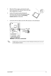
ASUS M4N68T 1-9 When the CPU is locked. 6. You can occur if you fail to section 1.6.2 Installing heatsink and fan for instructions. 7. Hardware monitoring errors can also refer to plug this connector. The lever clicks on the motherboard. M4N68T CPU_FAN CPU FAN PWM CPU FAN IN CPU FAN PWR GND M4N68T CPU fan connector DO NOT...
ASUS M4N68T 1-9 When the CPU is locked. 6. You can occur if you fail to section 1.6.2 Installing heatsink and fan for instructions. 7. Hardware monitoring errors can also refer to plug this connector. The lever clicks on the motherboard. M4N68T CPU_FAN CPU FAN PWM CPU FAN IN CPU FAN PWR GND M4N68T CPU fan connector DO NOT...
User Manual
Page 21
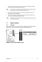
... figure illustrates the location of the retention bracket to the module base. 5. Align the other end of the DDR3 DIMM sockets: DIMM_A2 DIMM_B2 DIMM_A1 DIMM_B1 M4N68T Channel Channel A Channel B Sockets DIMM_A1 and DIMM_A2 DIMM_B1 and DIMM_B2 M4N68T 240-pin DDR3 DIMM sockets ASUS M4N68T 1-11 3.
... figure illustrates the location of the retention bracket to the module base. 5. Align the other end of the DDR3 DIMM sockets: DIMM_A2 DIMM_B2 DIMM_A1 DIMM_B1 M4N68T Channel Channel A Channel B Sockets DIMM_A1 and DIMM_A2 DIMM_B1 and DIMM_B2 M4N68T 240-pin DDR3 DIMM sockets ASUS M4N68T 1-11 3.
User Manual
Page 23
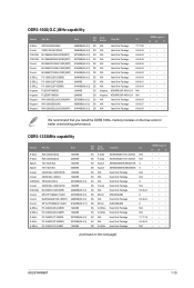
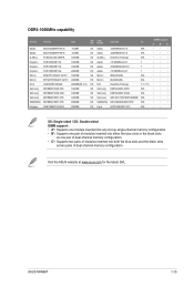
...; • • • • • • • • • • • We recommend that you install the DDR3 1600+ memory modules on the next page) ASUS M4N68T 1-13 DDR3-1333MHz capability Vendor Part No. DDR3-1600(O.C.)MHz capability Vendor Part No.
...; • • • • • • • • • • • We recommend that you install the DDR3 1600+ memory modules on the next page) ASUS M4N68T 1-13 DDR3-1333MHz capability Vendor Part No. DDR3-1600(O.C.)MHz capability Vendor Part No.
User Manual
Page 25
Size SS/ Chip DS Brand Chip NO. ASUS M4N68T 1-15 Visit the ASUS website at www.asus.com for the latest QVL. DDR3-1066MHz capability Vendor Part No. CL Elpida EBJ51UD8BAFA-AC-E 512MB SS Elpida EBJ51UD8BAFA-AE-E 512MB SS G.SKILL F3-8500CL6D-...
Size SS/ Chip DS Brand Chip NO. ASUS M4N68T 1-15 Visit the ASUS website at www.asus.com for the latest QVL. DDR3-1066MHz capability Vendor Part No. CL Elpida EBJ51UD8BAFA-AC-E 512MB SS Elpida EBJ51UD8BAFA-AE-E 512MB SS G.SKILL F3-8500CL6D-...
User Manual
Page 27
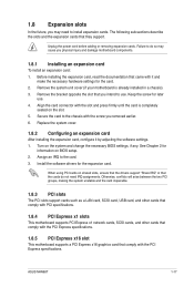
Unplug the power cord before adding or removing expansion cards. Secure the card to use . 4. ASUS M4N68T 1-17 Turn on BIOS setup. 2. See Chapter 2 for the card. 2. Install the software drivers for later use . Otherwise, conflicts will arise between the two PCI ...
Unplug the power cord before adding or removing expansion cards. Secure the card to use . 4. ASUS M4N68T 1-17 Turn on BIOS setup. 2. See Chapter 2 for the card. 2. Install the software drivers for later use . Otherwise, conflicts will arise between the two PCI ...

User Manual
Page 29
... a corresponding setting in low power mode) using the connected USB devices. KBPWR 12 23 +5V +5VSB (Default) M4N68T M4N68T Keyboard Power Setting ASUS M4N68T 1-19 USBPW1-4 12 23 M4N68T +5V +5VSB (Default) USBPW5-10 12 23 +5V +5VSB (Default) M4N68T USB Device Wake Up 3. Keyboard power (3-pin KBPWR) This jumper allows you to pins 2-3 (+5VSB), you...
... a corresponding setting in low power mode) using the connected USB devices. KBPWR 12 23 +5V +5VSB (Default) M4N68T M4N68T Keyboard Power Setting ASUS M4N68T 1-19 USBPW1-4 12 23 M4N68T +5V +5VSB (Default) USBPW5-10 12 23 +5V +5VSB (Default) M4N68T USB Device Wake Up 3. Keyboard power (3-pin KBPWR) This jumper allows you to pins 2-3 (+5VSB), you...
User Manual
Page 31
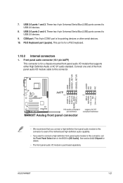
...AAFP) This connector is for pointing devices or other serial devices. 10. GND PRESENCE# SENSE1_RETUR SENSE2_RETUR AGND NC NC NC M4N68T AAFP PIN 1 PIN 1 MIC2 MICPWR Line out_R NC Line out_L PORT1 L PORT1 R PORT2 R SENSE_SEND PORT2 L HD-audio-compliant pin definition...module is for a chassis-mounted front panel audio I /O module cable to this connector, set the Front Panel Select item in the BIOS to this connector. ASUS M4N68T 1-21 See section 2.4.3 Chipset for a PS/2 keyboard. 1.10.2 Internal connectors 1. Connect one end of the front panel audio I /O module that you ...
...AAFP) This connector is for pointing devices or other serial devices. 10. GND PRESENCE# SENSE1_RETUR SENSE2_RETUR AGND NC NC NC M4N68T AAFP PIN 1 PIN 1 MIC2 MICPWR Line out_R NC Line out_L PORT1 L PORT1 R PORT2 R SENSE_SEND PORT2 L HD-audio-compliant pin definition...module is for a chassis-mounted front panel audio I /O module cable to this connector, set the Front Panel Select item in the BIOS to this connector. ASUS M4N68T 1-21 See section 2.4.3 Chipset for a PS/2 keyboard. 1.10.2 Internal connectors 1. Connect one end of the front panel audio I /O module that you ...
User Manual
Page 33
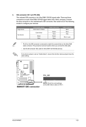
... 20 on the IDE connector is removed to match the covered hole on each Ultra DMA 133/100 signal cable: blue, black, and gray. M4N68T PRI_IDE M4N68T IDE connector PIN1 NOTE:Orient the red markings on the IDE ribbon cable to configure your devices: Single device Two devices Drive jumper setting Cable... other device jumpers have the same setting. Connect the blue connector to the motherboard's IDE connector, then select one of the following modes to PIN 1. ASUS M4N68T 1-23
... 20 on the IDE connector is removed to match the covered hole on each Ultra DMA 133/100 signal cable: blue, black, and gray. M4N68T PRI_IDE M4N68T IDE connector PIN1 NOTE:Orient the red markings on the IDE ribbon cable to configure your devices: Single device Two devices Drive jumper setting Cable... other device jumpers have the same setting. Connect the blue connector to the motherboard's IDE connector, then select one of the following modes to PIN 1. ASUS M4N68T 1-23

User Manual
Page 35
... drive activity LED (2-pin HDLED) This 2-pin connector is for the HDD Activity LED. PWR LED PWR BTN PLED+ PLEDPWR GND M4N68T F_PANEL PIN 1 IDE_LED+ IDE_LED- 6. Ground Reset HD_LED RESET M4N68T System panel connector • System power LED (2-pin PWRLED) This 2-pin connector is for the system power LED. System panel connector...) This 2-pin connector is for the system power button. • Reset button (2-pin RESET) This 2-pin connector is read from or written to this connector. ASUS M4N68T 1-25 Connect the HDD Activity LED cable to this connector.
... drive activity LED (2-pin HDLED) This 2-pin connector is for the HDD Activity LED. PWR LED PWR BTN PLED+ PLEDPWR GND M4N68T F_PANEL PIN 1 IDE_LED+ IDE_LED- 6. Ground Reset HD_LED RESET M4N68T System panel connector • System power LED (2-pin PWRLED) This 2-pin connector is for the system power LED. System panel connector...) This 2-pin connector is for the system power button. • Reset button (2-pin RESET) This 2-pin connector is read from or written to this connector. ASUS M4N68T 1-25 Connect the HDD Activity LED cable to this connector.
User Manual
Page 37
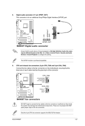
... on the fan connectors. Only the 4-pin CPU fan connector supports the ASUS Q-Fan feature. Go to Start > Control Panel > Sounds and Audio Devices > Sound Playback to the fan connectors. ASUS M4N68T 1-27 Digital audio connector (4-1 pin SPDIF_OUT) This connector is for an... additional Sony/Philips Digital Interface (S/PDIF) port. +5V SPDIFOUT GND M4N68T SPDIF_OUT M4N68T Digital audio connector Ensure that the black wire of each cable...
... on the fan connectors. Only the 4-pin CPU fan connector supports the ASUS Q-Fan feature. Go to Start > Control Panel > Sounds and Audio Devices > Sound Playback to the fan connectors. ASUS M4N68T 1-27 Digital audio connector (4-1 pin SPDIF_OUT) This connector is for an... additional Sony/Philips Digital Interface (S/PDIF) port. +5V SPDIFOUT GND M4N68T SPDIF_OUT M4N68T Digital audio connector Ensure that the black wire of each cable...
User Manual
Page 39
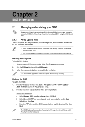
... select the BIOS version that allows you update the BIOS using the ASUS Update utility. 2.1.1 ASUS Update utility The ASUS Update is available in the support DVD that comes with the motherboard package. ASUS M4N68T 2-1 Select Update BIOS from the Internet a. c. The Drivers menu ...appears. 2. Place the support DVD into the optical drive. From the Windows® desktop, click Start > Programs > ASUS > ASUS Update > ASUS Update to complete the installation...
... select the BIOS version that allows you update the BIOS using the ASUS Update utility. 2.1.1 ASUS Update utility The ASUS Update is available in the support DVD that comes with the motherboard package. ASUS M4N68T 2-1 Select Update BIOS from the Internet a. c. The Drivers menu ...appears. 2. Place the support DVD into the optical drive. From the Windows® desktop, click Start > Programs > ASUS > ASUS Update > ASUS Update to complete the installation...
User Manual
Page 41
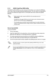
... Before using this utility. Refer to the optical drive or the removable device that ASUS CrashFree BIOS supports vary with motherboard models. Insert the support DVD to section 2.8 Exit menu for the BIOS file. ASUS M4N68T 2-3 Doing so can restore a corrupted BIOS file using this utility, rename the BIOS... file in the removable device into M4N68T.ROM. • The BIOS file in the support DVD may not be the...
... Before using this utility. Refer to the optical drive or the removable device that ASUS CrashFree BIOS supports vary with motherboard models. Insert the support DVD to section 2.8 Exit menu for the BIOS file. ASUS M4N68T 2-3 Doing so can restore a corrupted BIOS file using this utility, rename the BIOS... file in the removable device into M4N68T.ROM. • The BIOS file in the support DVD may not be the...
User Manual
Page 43
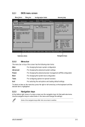
... settings Power For changing the advanced power management (APM) configuration Boot For changing the system boot configuration Tools For configuring options for that particular menu. ASUS M4N68T 2-5 Change Field Tab Select Field F1 General Help F10 Save and Exit ESC Exit v02.61 (C)Copyright 1985-2009, American Megatrends, Inc. Use the navigation...
... settings Power For changing the advanced power management (APM) configuration Boot For changing the system boot configuration Tools For configuring options for that particular menu. ASUS M4N68T 2-5 Change Field Tab Select Field F1 General Help F10 Save and Exit ESC Exit v02.61 (C)Copyright 1985-2009, American Megatrends, Inc. Use the navigation...

User Manual
Page 45
... you to set the system date. 2.3.3 IDE Configuration The IDE Configuration menu allows you an overview of the basic system information. Configuration options: [Disabled] [Enabled] ASUS M4N68T 2-7 Onboard IDE Controller [Enabled] Enables or disables the onboard IDE port. Configuration options: [Disabled] [Enabled] Serial-ATA Devices [SATA1,2,3,4] Configuration options: [Disabled] [SATA 1,2] [SATA1,2,3,4] nVidia...
... you to set the system date. 2.3.3 IDE Configuration The IDE Configuration menu allows you an overview of the basic system information. Configuration options: [Disabled] [Enabled] ASUS M4N68T 2-7 Onboard IDE Controller [Enabled] Enables or disables the onboard IDE port. Configuration options: [Disabled] [Enabled] Serial-ATA Devices [SATA1,2,3,4] Configuration options: [Disabled] [SATA 1,2] [SATA1,2,3,4] nVidia...
User Manual
Page 47
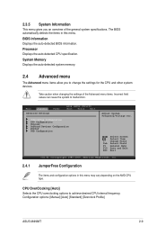
... automatically detects the items in this menu. Take caution when changing the settings of the general system specifications. Configuration options: [Manual] [Auto] [Standard] [Overclock Profile] ASUS M4N68T 2-9 Select Screen Select Item +-
... automatically detects the items in this menu. Take caution when changing the settings of the general system specifications. Configuration options: [Manual] [Auto] [Standard] [Overclock Profile] ASUS M4N68T 2-9 Select Screen Select Item +-
User Manual
Page 49
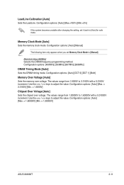
....=0%] If the system becomes unstable after changing the setting, set Memory Clock Mode to [Auto] for safe mode. Configuration options: [Auto] [Max. = 1.60000V] [Min. = 1.20000V] ASUS M4N68T 2-11 Configuration options: [Auto] [Manual] The following item only appears when you set it back to [Manual]. Configuration options: [400MHz] [533MHz] [667MHz] [800MHz] DRAM Timing...
....=0%] If the system becomes unstable after changing the setting, set Memory Clock Mode to [Auto] for safe mode. Configuration options: [Auto] [Max. = 1.60000V] [Min. = 1.20000V] ASUS M4N68T 2-11 Configuration options: [Auto] [Manual] The following item only appears when you set it back to [Manual]. Configuration options: [400MHz] [533MHz] [667MHz] [800MHz] DRAM Timing...


