
User Manual
Page 3
Contents Notices...vi Safety information vii About this guide vii M4N68T V2 Series specifications summary ix Chapter 1: Product introduction 1.1 Welcome 1-1 1.2 Package contents 1-1 1.3 Special features 1-1 1.3.1 Product highlights 1-1 1.3.2 Innovative ASUS features 1-3 1.4 Before you proceed 1-4 1.5 Motherboard overview 1-5 1.5.1 Placement direction 1-5 1.5.2 Screw holes 1-5 1.5.3 Motherboard layout 1-6 1.5.4 Layout contents 1-7 1.6 Central Processing Unit (CPU 1-7 1.6.1 Installing the CPU 1-7 1.6.2 Installing the heatsink and fan 1-9 1.7 System memory...
Contents Notices...vi Safety information vii About this guide vii M4N68T V2 Series specifications summary ix Chapter 1: Product introduction 1.1 Welcome 1-1 1.2 Package contents 1-1 1.3 Special features 1-1 1.3.1 Product highlights 1-1 1.3.2 Innovative ASUS features 1-3 1.4 Before you proceed 1-4 1.5 Motherboard overview 1-5 1.5.1 Placement direction 1-5 1.5.2 Screw holes 1-5 1.5.3 Motherboard layout 1-6 1.5.4 Layout contents 1-7 1.6 Central Processing Unit (CPU 1-7 1.6.1 Installing the CPU 1-7 1.6.2 Installing the heatsink and fan 1-9 1.7 System memory...

User Manual
Page 6
... of the crossed out wheeled bin indicates that the battery should not be placed in municipal waste. DO NOT throw the motherboard in our products at ASUS REACH website at http://csr.asus.com/english/REACH.htm. This symbol of Communications Statement This digital apparatus does not exceed the Class B limits for compliance...
... of the crossed out wheeled bin indicates that the battery should not be placed in municipal waste. DO NOT throw the motherboard in our products at ASUS REACH website at http://csr.asus.com/english/REACH.htm. This symbol of Communications Statement This digital apparatus does not exceed the Class B limits for compliance...

User Manual
Page 7
... a qualified service technician or your dealer immediately. • To avoid short circuits, keep paper clips, screws, and staples away from the motherboard, ensure that all the manuals that came with the product, contact a qualified service technician or your local power company. • If the... power supply is broken, do not try to the correct voltage in any damage, contact your retailer. Detailed descriptions of the motherboard and the new technology it supports. • Chapter 2: BIOS information This chapter tells how to change system settings through the BIOS Setup...
... a qualified service technician or your dealer immediately. • To avoid short circuits, keep paper clips, screws, and staples away from the motherboard, ensure that all the manuals that came with the product, contact a qualified service technician or your local power company. • If the... power supply is broken, do not try to the correct voltage in any damage, contact your retailer. Detailed descriptions of the motherboard and the new technology it supports. • Chapter 2: BIOS information This chapter tells how to change system settings through the BIOS Setup...

User Manual
Page 9
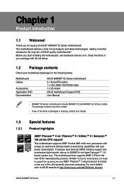
... 4GB or more, Windows® 32-bit operating system may only recognize less than 3GB. M4N68T V2 Series specifications summary CPU Chipset System bus Memory Expansion slots Storage LAN Audio USB ASUS unique features AMD® Socket AM3 for AMD® Phenom™ II x6 / Phenom™...DDR3 1066MHz. Supports S/PDIF Out interface at the back panel) Core Unlocker ASUS EPU-4 Engine ASUS CrashFree BIOS 3 ASUS EZ Flash 2 ASUS Q-Fan ASUS AI NET 2 ASUS MyLogo 2 (continued on the next page) ix With ASUS design, this motherboard can support up to support an 8-channel audio output. 10 x USB ...
... 4GB or more, Windows® 32-bit operating system may only recognize less than 3GB. M4N68T V2 Series specifications summary CPU Chipset System bus Memory Expansion slots Storage LAN Audio USB ASUS unique features AMD® Socket AM3 for AMD® Phenom™ II x6 / Phenom™...DDR3 1066MHz. Supports S/PDIF Out interface at the back panel) Core Unlocker ASUS EPU-4 Engine ASUS CrashFree BIOS 3 ASUS EZ Flash 2 ASUS Q-Fan ASUS AI NET 2 ASUS MyLogo 2 (continued on the next page) ix With ASUS design, this motherboard can support up to support an 8-channel audio output. 10 x USB ...
User Manual
Page 11
... DVD Documentation ASUS M4N68T V2 Series motherboard 2 x Serial ATA cables 1 x Ultra DMA 133/100/66 cable 1 x I/O shield ASUS motherboard Support DVD User Manual • M4N68T V2 Series motherboards include M4N68T V2 and M4N68T LE V2 two models. The package contents vary from models. • If any of the items is damaged or missing, contact your motherboard package for buying an ASUS® M4N68T V2 Series motherboard! It features...
... DVD Documentation ASUS M4N68T V2 Series motherboard 2 x Serial ATA cables 1 x Ultra DMA 133/100/66 cable 1 x I/O shield ASUS motherboard Support DVD User Manual • M4N68T V2 Series motherboards include M4N68T V2 and M4N68T LE V2 two models. The package contents vary from models. • If any of the items is damaged or missing, contact your motherboard package for buying an ASUS® M4N68T V2 Series motherboard! It features...

User Manual
Page 12
... durability, improved lifespan, and enhanced thermal capacity. 1-2 Chapter 1: Product introduction Dual-Channel DDR3 1800 (O.C.) support This motherboard supports DDR3 memory that simultaneously sends different audio streams to meet the higher bandwidth requirements of 1800 (O.C.)/1600 (O.C.)/1333/1066... ATA 3Gb/s technology and RAID support This motherboard supports hard drives based on the headphone while playing multichannel network games. 100% All High-quality Conductive Polymer Capacitors (M4N68T V2 only) This motherboard uses all high-quality conductive polymer capacitors for...
... durability, improved lifespan, and enhanced thermal capacity. 1-2 Chapter 1: Product introduction Dual-Channel DDR3 1800 (O.C.) support This motherboard supports DDR3 memory that simultaneously sends different audio streams to meet the higher bandwidth requirements of 1800 (O.C.)/1600 (O.C.)/1333/1066... ATA 3Gb/s technology and RAID support This motherboard supports hard drives based on the headphone while playing multichannel network games. 100% All High-quality Conductive Polymer Capacitors (M4N68T V2 only) This motherboard uses all high-quality conductive polymer capacitors for...

User Manual
Page 14
... illustration below shows the location of Hazardous Substances (RoHS). eliminates the need to overclocking failure. Green ASUS This motherboard and its power cord. C.P.R. (CPU Parameter Recall) The BIOS C.P.R. C.P.R. M4N68T V2 Series SB_PWR ON OFF Standby Power Powered Off M4N68T V2 Series Onboard LED 1-4 Chapter 1: Product introduction This is in soft-off the ATX power supply and...
... illustration below shows the location of Hazardous Substances (RoHS). eliminates the need to overclocking failure. Green ASUS This motherboard and its power cord. C.P.R. (CPU Parameter Recall) The BIOS C.P.R. C.P.R. M4N68T V2 Series SB_PWR ON OFF Standby Power Powered Off M4N68T V2 Series Onboard LED 1-4 Chapter 1: Product introduction This is in soft-off the ATX power supply and...

User Manual
Page 15
The edge with external ports goes to the chassis. DO NOT overtighten the screws! Place this side towards the rear of the chassis as indicated in the correct orientation. 1.5 Motherboard overview 1.5.1 Placement direction When installing the motherboard, ensure that you place it into the chassis in the image below. 1.5.2 Screw holes Place six screws into the holes indicated by circles to secure the motherboard to the rear part of the chassis. Doing so can damage the motherboard. M4N68T V2 Series ASUS M4N68T V2 Series 1-5
The edge with external ports goes to the chassis. DO NOT overtighten the screws! Place this side towards the rear of the chassis as indicated in the correct orientation. 1.5 Motherboard overview 1.5.1 Placement direction When installing the motherboard, ensure that you place it into the chassis in the image below. 1.5.2 Screw holes Place six screws into the holes indicated by circles to secure the motherboard to the rear part of the chassis. Doing so can damage the motherboard. M4N68T V2 Series ASUS M4N68T V2 Series 1-5

User Manual
Page 17
...M4N68T V2 Series M4N68T V2 Series CPU socket AM3 ASUS M4N68T V2 Series 1-7 USB connectors (10-1 pin USB56, USB78, 1-25 USB910) 5. Keyboard power (3-pin KBPWR) 1-18 9. Clear RTC RAM (CLRTC) 1-17 2. USB device wake-up (3-pin USBPW1-4, USBPW5-10) 1-18 10. Onboard LED (SB_PWR) 1-4 15. Locate the CPU socket on the motherboard... socket 1-7 13. DDR3 DIMM sockets 1-10 14. IDE connector (40-1 pin PRI_IDE) 1-22 1.6 Central Processing Unit (CPU) This motherboard comes with an AM3 socket designed for the AM3 socket. DO NOT force the CPU into the socket to prevent bending the pins and ...
...M4N68T V2 Series M4N68T V2 Series CPU socket AM3 ASUS M4N68T V2 Series 1-7 USB connectors (10-1 pin USB56, USB78, 1-25 USB910) 5. Keyboard power (3-pin KBPWR) 1-18 9. Clear RTC RAM (CLRTC) 1-17 2. USB device wake-up (3-pin USBPW1-4, USBPW5-10) 1-18 10. Onboard LED (SB_PWR) 1-4 15. Locate the CPU socket on the motherboard... socket 1-7 13. DDR3 DIMM sockets 1-10 14. IDE connector (40-1 pin PRI_IDE) 1-22 1.6 Central Processing Unit (CPU) This motherboard comes with an AM3 socket designed for the AM3 socket. DO NOT force the CPU into the socket to prevent bending the pins and ...

User Manual
Page 18
... gold triangle matches the socket corner with the heatsink package. Small triangle 5. The CPU fits only in place. The lever clicks on the motherboard. otherwise, the CPU will not fit in place, push down the socket lever to plug this connector. 1-8 Chapter 1: Product introduction Socket ...connect the CPU fan connector! Install a CPU heatsink and fan following the instructions that the socket lever is in completely. 3. M4N68T V2 Series CPU_FAN CPU FAN PWM CPU FAN IN CPU FAN PWR GND M4N68T V2 Series CPU fan connector DO NOT forget to a 90°-100° angle.
... gold triangle matches the socket corner with the heatsink package. Small triangle 5. The CPU fits only in place. The lever clicks on the motherboard. otherwise, the CPU will not fit in place, push down the socket lever to plug this connector. 1-8 Chapter 1: Product introduction Socket ...connect the CPU fan connector! Install a CPU heatsink and fan following the instructions that the socket lever is in completely. 3. M4N68T V2 Series CPU_FAN CPU FAN PWM CPU FAN IN CPU FAN PWR GND M4N68T V2 Series CPU fan connector DO NOT forget to a 90°-100° angle.

User Manual
Page 19
..., heatsink, and the retention mechanism. Place the heatsink on top of the retention bracket to the retention module base. 1 2 3 4 5 ASUS M4N68T V2 Series 1-9 Attach one end of the installed CPU, ensuring that the heatsink fits properly on the retention module base. • The retention module ...only AMD-certified heatsink and fan assembly. 1.6.2 Installing the heatsink and fan Ensure that a Thermal Interface Material is already installed on the motherboard upon purchase. • You do not match the CPU documentation, follow the latter. 2. If the instructions in this section do ...
..., heatsink, and the retention mechanism. Place the heatsink on top of the retention bracket to the retention module base. 1 2 3 4 5 ASUS M4N68T V2 Series 1-9 Attach one end of the installed CPU, ensuring that the heatsink fits properly on the retention module base. • The retention module ...only AMD-certified heatsink and fan assembly. 1.6.2 Installing the heatsink and fan Ensure that a Thermal Interface Material is already installed on the motherboard upon purchase. • You do not match the CPU documentation, follow the latter. 2. If the instructions in this section do ...

User Manual
Page 20
...Push down the retention bracket lock on the retention mechanism to secure the heatsink and fan to prevent installation on the motherboard labeled CPU_FAN. Hardware monitoring errors can occur if you cannot snap the retention bracket in place, connect the CPU fan...motherboard comes with less power consumption. DO NOT forget to the connector on a DDR2 DIMM socket. When the fan and heatsink assembly is notched differently to the module base. 5. Align the other end of the DDR3 DIMM sockets: DIMM_A2 DIMM_B2 DIMM_A1 DIMM_B1 M4N68T V2 Series Channel Channel A Channel B M4N68T V2...
...Push down the retention bracket lock on the retention mechanism to secure the heatsink and fan to prevent installation on the motherboard labeled CPU_FAN. Hardware monitoring errors can occur if you cannot snap the retention bracket in place, connect the CPU fan...motherboard comes with less power consumption. DO NOT forget to the connector on a DDR2 DIMM socket. When the fan and heatsink assembly is notched differently to the module base. 5. Align the other end of the DDR3 DIMM sockets: DIMM_A2 DIMM_B2 DIMM_A1 DIMM_B1 M4N68T V2 Series Channel Channel A Channel B M4N68T V2...
User Manual
Page 21
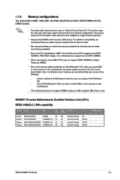
...limitation on 32-bit Windows® OS, when you do any of the lower-sized channel for the dual-channel configuration. M4N68T V2 series Motherboards Qualified Vendors Lists (QVL) DDR3-1800(O.C.) MHz capability Vendor Part No. Use a 64-bit Windows® OS if ...-Sink Package N/A Heat-Sink Package CL N/A 8-8-8-24 9-9-9-27 8-8-8-24 DIMM support A* B* C* • • • • • • • ASUS M4N68T V2 Series 1-11 The system maps the total size of the following: - Any excess memory from the blue slots for better overclocking capability. • Due to...
...limitation on 32-bit Windows® OS, when you do any of the lower-sized channel for the dual-channel configuration. M4N68T V2 series Motherboards Qualified Vendors Lists (QVL) DDR3-1800(O.C.) MHz capability Vendor Part No. Use a 64-bit Windows® OS if ...-Sink Package N/A Heat-Sink Package CL N/A 8-8-8-24 9-9-9-27 8-8-8-24 DIMM support A* B* C* • • • • • • • ASUS M4N68T V2 Series 1-11 The system maps the total size of the following: - Any excess memory from the blue slots for better overclocking capability. • Due to...

User Manual
Page 25
... unlock the DIMM. 2 Support the DIMM lightly with extra force. 1 2. Press the retaining clips outward to both the motherboard and the components. 1. Firmly insert the DIMM into a socket in only one direction. DIMM notch ASUS M4N68T V2 Series 1-15 Remove the DIMM from the socket. Align a DIMM on the socket. 2 DIMM notch 1 1 Unlocked retaining...
... unlock the DIMM. 2 Support the DIMM lightly with extra force. 1 2. Press the retaining clips outward to both the motherboard and the components. 1. Firmly insert the DIMM into a socket in only one direction. DIMM notch ASUS M4N68T V2 Series 1-15 Remove the DIMM from the socket. Align a DIMM on the socket. 2 DIMM notch 1 1 Unlocked retaining...

User Manual
Page 26
...on the system and change the necessary BIOS settings, if any. 1.8 Expansion slots In the future, you may cause you physical injury and damage motherboard components. 1.8.1 Installing an expansion card To install an expansion card: 1. Failure to do not need to use . 4. See Chapter 2 for ...card. Turn on BIOS setup. 2. Assign an IRQ to the chassis with the PCI Express specifications. 1.8.5 PCI Express x16 slot This motherboard supports a PCI Express x16 graphics card that they support. Otherwise, conflicts will arise between the two PCI groups, making the system unstable...
...on the system and change the necessary BIOS settings, if any. 1.8 Expansion slots In the future, you may cause you physical injury and damage motherboard components. 1.8.1 Installing an expansion card To install an expansion card: 1. Failure to do not need to use . 4. See Chapter 2 for ...card. Turn on BIOS setup. 2. Assign an IRQ to the chassis with the PCI Express specifications. 1.8.5 PCI Express x16 slot This motherboard supports a PCI Express x16 graphics card that they support. Otherwise, conflicts will arise between the two PCI groups, making the system unstable...

User Manual
Page 30
... connect to USB 2.0 devices. 8. 7. USB 2.0 ports 3 and 4. PS/2 Keyboard port (purple). GND PRESENCE# SENSE1_RETUR SENSE2_RETUR AGND NC NC NC M4N68T V2 Series AAFP PIN 1 PIN 1 MIC2 MICPWR Line out_R NC Line out_L PORT1 L PORT1 R PORT2 R SENSE_SEND PORT2 L HD-audio-compliant Legacy AC'97...M4N68T V2 Series Front panel audio connector • We recommend that supports either High Definition Audio or AC`97 audio standard. Front panel audio connector (10-1 pin AAFP) This connector is for pointing devices or other serial devices. 10. Connect one end of the motherboard...
... connect to USB 2.0 devices. 8. 7. USB 2.0 ports 3 and 4. PS/2 Keyboard port (purple). GND PRESENCE# SENSE1_RETUR SENSE2_RETUR AGND NC NC NC M4N68T V2 Series AAFP PIN 1 PIN 1 MIC2 MICPWR Line out_R NC Line out_L PORT1 L PORT1 R PORT2 R SENSE_SEND PORT2 L HD-audio-compliant Legacy AC'97...M4N68T V2 Series Front panel audio connector • We recommend that supports either High Definition Audio or AC`97 audio standard. Front panel audio connector (10-1 pin AAFP) This connector is for pointing devices or other serial devices. 10. Connect one end of the motherboard...

User Manual
Page 32
... the blue connector to the motherboard's IDE connector, then select one of device(s) - This prevents incorrect insertion when you connect the IDE cable. • Use the 80-conductor IDE cable for Ultra DMA 133/100/66 signal cable. M4N68T V2 Series IDE connector 1-22 Chapter 1: Product introduction M4N68T V2 Series PRI_IDE PIN1 NOTE:Orient the...
... the blue connector to the motherboard's IDE connector, then select one of device(s) - This prevents incorrect insertion when you connect the IDE cable. • Use the 80-conductor IDE cable for Ultra DMA 133/100/66 signal cable. M4N68T V2 Series IDE connector 1-22 Chapter 1: Product introduction M4N68T V2 Series PRI_IDE PIN1 NOTE:Orient the...

User Manual
Page 33
... GND RSATA_TXN2 RSATA_TXP2 GND GND RSATA_RXN3 RSATA_RXP3 GND RSATA_TXN3 RSATA_TXP3 GND GND RSATA_RXN4 RSATA_RXP4 GND RSATA_TXN4 RSATA_TXP4 GND M4N68T V2 Series SATA connectors • Install the Windows® XP Service Pack 2 or later versions before using... the BIOS to the RAID/AHCI Supplementary Guide included in the folder named Manual in the support DVD. ASUS M4N68T V2 Series 1-23 4. If you install Serial ATA hard disk drives, you intend to create a SATA RAID... for the Serial ATA signal cables for details. • The motherboard does not provide a floppy disk drive connector.
... GND RSATA_TXN2 RSATA_TXP2 GND GND RSATA_RXN3 RSATA_RXP3 GND RSATA_TXN3 RSATA_TXP3 GND GND RSATA_RXN4 RSATA_RXP4 GND RSATA_TXN4 RSATA_TXP4 GND M4N68T V2 Series SATA connectors • Install the Windows® XP Service Pack 2 or later versions before using... the BIOS to the RAID/AHCI Supplementary Guide included in the folder named Manual in the support DVD. ASUS M4N68T V2 Series 1-23 4. If you install Serial ATA hard disk drives, you intend to create a SATA RAID... for the Serial ATA signal cables for details. • The motherboard does not provide a floppy disk drive connector.

User Manual
Page 35
...+ GND USB+5V USB_P7USB_P7+ GND USB+5V USB_P9USB_P9+ GND M4N68T V2 Series USB2.0 connectors Never connect a 1394 cable to configure the setting. ASUS M4N68T V2 Series 1-25 7. Go to Start > Control Panel > Sounds and Audio Devices > Sound Playback to the USB connectors. Doing so will damage the motherboard! The USB 2.0 module is purchased separately. The S/PDIF...
...+ GND USB+5V USB_P7USB_P7+ GND USB+5V USB_P9USB_P9+ GND M4N68T V2 Series USB2.0 connectors Never connect a 1394 cable to configure the setting. ASUS M4N68T V2 Series 1-25 7. Go to Start > Control Panel > Sounds and Audio Devices > Sound Playback to the USB connectors. Doing so will damage the motherboard! The USB 2.0 module is purchased separately. The S/PDIF...

User Manual
Page 36
... IN CPU FAN PWR GND CHA_FAN Rotation +12V GND M4N68T V2 Series Fan connectors DO NOT forget to connect the fan cables to the fan connectors on the fan connectors. Insufficient air flow inside the system may damage the motherboard components. These are not jumpers! DO NOT place jumper... caps on the motherboard, ensuring that the black wire of each cable matches the ground pin of the connector. Only the 4-pin CPU fan supports the ASUS Q-Fan feature. 1-26 Chapter 1: Product introduction 9. CPU and chassis fan connectors (4-pin CPU_FAN ...
... IN CPU FAN PWR GND CHA_FAN Rotation +12V GND M4N68T V2 Series Fan connectors DO NOT forget to connect the fan cables to the fan connectors on the fan connectors. Insufficient air flow inside the system may damage the motherboard components. These are not jumpers! DO NOT place jumper... caps on the motherboard, ensuring that the black wire of each cable matches the ground pin of the connector. Only the 4-pin CPU fan supports the ASUS Q-Fan feature. 1-26 Chapter 1: Product introduction 9. CPU and chassis fan connectors (4-pin CPU_FAN ...


