
User Manual
Page 4
Contents 1.11 Software support 1-29 1.11.1 Installing an operating system 1-29 1.11.2 Support DVD information 1-29 Chapter 2: BIOS information 2.1 Managing and updating your BIOS 2-1 2.1.1 ASUS Update 2-1 2.1.2 ASUS EZ Flash 2 2-2 2.1.3 ASUS CrashFree BIOS 3 2-3 2.2 BIOS setup program 2-4 2.2.1 BIOS menu screen 2-5 2.2.2 Menu bar 2-5 2.2.3 Navigation keys 2-5 2.2.4 Menu items 2-6 2.2.5 Submenu items 2-6 2.2.6 Configuration fields 2-6 2.2.7 Pop-up window 2-6 2.2.8 Scroll bar 2-6 2.2.9 General help 2-6 2.3 Main menu 2-7 2.3.1 System Time...
Contents 1.11 Software support 1-29 1.11.1 Installing an operating system 1-29 1.11.2 Support DVD information 1-29 Chapter 2: BIOS information 2.1 Managing and updating your BIOS 2-1 2.1.1 ASUS Update 2-1 2.1.2 ASUS EZ Flash 2 2-2 2.1.3 ASUS CrashFree BIOS 3 2-3 2.2 BIOS setup program 2-4 2.2.1 BIOS menu screen 2-5 2.2.2 Menu bar 2-5 2.2.3 Navigation keys 2-5 2.2.4 Menu items 2-6 2.2.5 Submenu items 2-6 2.2.6 Configuration fields 2-6 2.2.7 Pop-up window 2-6 2.2.8 Scroll bar 2-6 2.2.9 General help 2-6 2.3 Main menu 2-7 2.3.1 System Time...

User Manual
Page 7
... This chapter describes the features of the motherboard and the new technology it supports. • Chapter 2: BIOS information This chapter tells how to change system settings through the BIOS Setup menus. If possible, disconnect all the manuals that came with the product, contact a qualified service technician... or your retailer. If you are not sure about the voltage of the BIOS parameters are also provided. Do not place the product in your area. Contact a qualified service technician or your local power company. &#...
... This chapter describes the features of the motherboard and the new technology it supports. • Chapter 2: BIOS information This chapter tells how to change system settings through the BIOS Setup menus. If possible, disconnect all the manuals that came with the product, contact a qualified service technician... or your retailer. If you are not sure about the voltage of the BIOS parameters are also provided. Do not place the product in your area. Contact a qualified service technician or your local power company. &#...
User Manual
Page 9
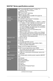
...more, Windows® 32-bit operating system may only recognize less than 3GB. M4A78LT Series specifications summar CPU Chipset System bus Memory Expansion slots Storage LAN Audio USB Special features ASUS unique features AMD® Socket AM3 AMD® Phenom™ II / ... at the mid-board, 4 ports at the back panel) 100% All high quality conductive polymer capacitors (M4A78LT only) Core Unlocker ASUS EPU-4 Engine ASUS CrashFree BIOS 3 ASUS EZ Flash 2 ASUS Q-Fan ASUS MyLogo 2 ASUS C.P.R. (CPU Parameter Recall) ASUS Anti Surge ASUS AI Charger ASUS Turbo Key (continued on the next page) ix
...more, Windows® 32-bit operating system may only recognize less than 3GB. M4A78LT Series specifications summar CPU Chipset System bus Memory Expansion slots Storage LAN Audio USB Special features ASUS unique features AMD® Socket AM3 AMD® Phenom™ II / ... at the mid-board, 4 ports at the back panel) 100% All high quality conductive polymer capacitors (M4A78LT only) Core Unlocker ASUS EPU-4 Engine ASUS CrashFree BIOS 3 ASUS EZ Flash 2 ASUS Q-Fan ASUS MyLogo 2 ASUS C.P.R. (CPU Parameter Recall) ASUS Anti Surge ASUS AI Charger ASUS Turbo Key (continued on the next page) ix
User Manual
Page 10
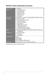
M4A78LT Series specifications summary Back panel I/O ports Internal I/O connectors BIOS Accessories Support DVD Form factor 1 x LPT port 1 x PS/2 Keyboard port 1 x PS/2 Mouse port 1 x LAN (RJ-45) port 4 x USB 2.0/1.1 ports 1 x COM connector 3 x Audio jacks 3 x USB ... Out connector 1 x 24-pin EATX power connector 1 x 4-pin ATX 12V power connector 8 Mb Flash ROM, AMI BIOS, PnP, DMI v2.0, WfM 2.0, ACPI v2.0a, SM BIOS v2.5 2 x Serial ATA cables 1 x I/O shield 1 x User Manual Drivers ASUS utilities ASUS Update Anti-virus software (OEM version) ATX form factor: 12 in x 8 in (30.5 cm x 20.3 cm) ...
M4A78LT Series specifications summary Back panel I/O ports Internal I/O connectors BIOS Accessories Support DVD Form factor 1 x LPT port 1 x PS/2 Keyboard port 1 x PS/2 Mouse port 1 x LAN (RJ-45) port 4 x USB 2.0/1.1 ports 1 x COM connector 3 x Audio jacks 3 x USB ... Out connector 1 x 24-pin EATX power connector 1 x 4-pin ATX 12V power connector 8 Mb Flash ROM, AMI BIOS, PnP, DMI v2.0, WfM 2.0, ACPI v2.0a, SM BIOS v2.5 2 x Serial ATA cables 1 x I/O shield 1 x User Manual Drivers ASUS utilities ASUS Update Anti-virus software (OEM version) ATX form factor: 12 in x 8 in (30.5 cm x 20.3 cm) ...
User Manual
Page 13
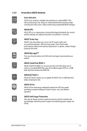
..., without interrupting ongoing work or games, simply through pressing the button. ASUS EZ Flash 2 ASUS EZ Flash 2 allows you to update the BIOS from switching power supply unit (PSU). ASUS MyLogo2™ Turn your favorite photos into an overclocking button. ASUS M4A78LT Series 1-3 ASUS Turbo Key ASUS Turbo Key allows you to turn the PC power button into...
..., without interrupting ongoing work or games, simply through pressing the button. ASUS EZ Flash 2 ASUS EZ Flash 2 allows you to update the BIOS from switching power supply unit (PSU). ASUS MyLogo2™ Turn your favorite photos into an overclocking button. ASUS M4A78LT Series 1-3 ASUS Turbo Key ASUS Turbo Key allows you to turn the PC power button into...

User Manual
Page 14
...;s Energy-related Products (ErP) ready, and ErP requires products to meet certain energy efficiency requirements in line with ASUS vision of creating environment-friendly and energy-efficient products through product design and innovation to reduce carbon footprint of the product... and thus mitigate environmental impacts. 1-4 Chapter 1: Product introduction C.P.R. Simply shut down and reboot the system, and the BIOS automatically restores the CPU parameters to overclocking failure. feature automatically restores the CPU default settings when the system hangs due to their default...
...;s Energy-related Products (ErP) ready, and ErP requires products to meet certain energy efficiency requirements in line with ASUS vision of creating environment-friendly and energy-efficient products through product design and innovation to reduce carbon footprint of the product... and thus mitigate environmental impacts. 1-4 Chapter 1: Product introduction C.P.R. Simply shut down and reboot the system, and the BIOS automatically restores the CPU parameters to overclocking failure. feature automatically restores the CPU default settings when the system hangs due to their default...
User Manual
Page 17
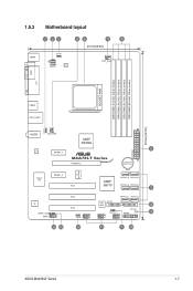
... CHA_FAN AMD® RS780L EATXPWR 2 RTL 8111E PCIEX1_1 M4A78LT Series PCIEX16_1 Lithium Cell CMOS Power ICS 9LPRS483 Super I/O PCIEX1_2 PCI1 SATA3G_5 SATA3G_6 AMD® SB710 SATA3G_3 SATA3G_4 7 ALC 887 SPDIF_OUT AAFP PCI2 SATA3G_1 SATA3G_2 PCI3 PRI_IDE 8Mb BIOS 8 SB_PWR USBPW5-10 PANEL 9 CLRTC USB56 USB78 USB910 14 13 12 11 1 10 ASUS M4A78LT Series 1-7
... CHA_FAN AMD® RS780L EATXPWR 2 RTL 8111E PCIEX1_1 M4A78LT Series PCIEX16_1 Lithium Cell CMOS Power ICS 9LPRS483 Super I/O PCIEX1_2 PCI1 SATA3G_5 SATA3G_6 AMD® SB710 SATA3G_3 SATA3G_4 7 ALC 887 SPDIF_OUT AAFP PCI2 SATA3G_1 SATA3G_2 PCI3 PRI_IDE 8Mb BIOS 8 SB_PWR USBPW5-10 PANEL 9 CLRTC USB56 USB78 USB910 14 13 12 11 1 10 ASUS M4A78LT Series 1-7

User Manual
Page 28
... components. 1.8.1 Installing an expansion card To install an expansion card: 1. Remove the system unit cover (if your motherboard is completely seated on BIOS setup. 2. Align the card connector with the PCI Express specifications. 1-18 Chapter 1: Product introduction See Chapter 2 for the card. 2. Assign...motherboard supports a PCI Express x16 graphics card that they support. When using PCI cards on the system and change the necessary BIOS settings, if any. The following sub‑sections describe the slots and the expansion cards that comply with the slot and ...
... components. 1.8.1 Installing an expansion card To install an expansion card: 1. Remove the system unit cover (if your motherboard is completely seated on BIOS setup. 2. Align the card connector with the PCI Express specifications. 1-18 Chapter 1: Product introduction See Chapter 2 for the card. 2. Assign...motherboard supports a PCI Express x16 graphics card that they support. When using PCI cards on the system and change the necessary BIOS settings, if any. The following sub‑sections describe the slots and the expansion cards that comply with the slot and ...

User Manual
Page 29
... 12 23 Normal (Default) M4A78LT Series Clear RTC RAM Clear RTC To erase the RTC RAM: 1. Shut down the key during the boot process and enter BIOS setup to clear the CMOS RTC RAM data. The onboard button cell battery powers the RAM data in CMOS. Plug the power cord and turn... so the BIOS can clear the CMOS memory of date, time, and system setup parameters by erasing the CMOS RTC RAM data. Removing the cap will cause system boot failure! • If the steps above do not need to clear the RTC when the system hangs due to default values. ASUS M4A78LT Series...
... 12 23 Normal (Default) M4A78LT Series Clear RTC RAM Clear RTC To erase the RTC RAM: 1. Shut down the key during the boot process and enter BIOS setup to clear the CMOS RTC RAM data. The onboard button cell battery powers the RAM data in CMOS. Plug the power cord and turn... so the BIOS can clear the CMOS memory of date, time, and system setup parameters by erasing the CMOS RTC RAM data. Removing the cap will cause system boot failure! • If the steps above do not need to clear the RTC when the system hangs due to default values. ASUS M4A78LT Series...

User Manual
Page 30
Keyboard power (3-pin KBPWR) This jumper allows you can supply at least 1A on the keyboard. KBPWR 12 23 +5V +5VSB (Default) M4A78LT Series M4A78LT Series Keyboard Power Setting 1-20 Chapter 1: Product introduction USB device wake-up (3-pin USBPW1-4, USBPW5-10) Set these jumpers to +5VSB to wake up the...and S4 sleep modes (no power to wake up feature. Set these jumpers to +5V to CPU, DRAM in slow refresh, power supply in the BIOS. This feature requires an ATX power supply that can wake up the compurer from S1 sleep mode (CPU stopped, DRAM refreshed, system running in low...
Keyboard power (3-pin KBPWR) This jumper allows you can supply at least 1A on the keyboard. KBPWR 12 23 +5V +5VSB (Default) M4A78LT Series M4A78LT Series Keyboard Power Setting 1-20 Chapter 1: Product introduction USB device wake-up (3-pin USBPW1-4, USBPW5-10) Set these jumpers to +5VSB to wake up the...and S4 sleep modes (no power to wake up feature. Set these jumpers to +5V to CPU, DRAM in slow refresh, power supply in the BIOS. This feature requires an ATX power supply that can wake up the compurer from S1 sleep mode (CPU stopped, DRAM refreshed, system running in low...

User Manual
Page 32
... I/O module that you want to connect a high definition front panel audio module to this connector, set the Front Panel Select item in the BIOS to this connector to avail of the front panel audio I/O module cable to [HD Audio]. These two 4-pin Universal Serial Bus (USB) ...-definition audio capability. • If you connect a high-definition front panel audio module to this connector. GND PRESENCE# SENSE1_RETUR SENSE2_RETUR AGND NC NC NC M4A78LT Series AAFP PIN 1 PIN 1 MIC2 MICPWR Line out_R NC Line out_L PORT1 L PORT1 R PORT2 R SENSE_SEND PORT2 L HD-audio-compliant Legacy AC'97...
... I/O module that you want to connect a high definition front panel audio module to this connector, set the Front Panel Select item in the BIOS to this connector to avail of the front panel audio I/O module cable to [HD Audio]. These two 4-pin Universal Serial Bus (USB) ...-definition audio capability. • If you connect a high-definition front panel audio module to this connector. GND PRESENCE# SENSE1_RETUR SENSE2_RETUR AGND NC NC NC M4A78LT Series AAFP PIN 1 PIN 1 MIC2 MICPWR Line out_R NC Line out_L PORT1 L PORT1 R PORT2 R SENSE_SEND PORT2 L HD-audio-compliant Legacy AC'97...
User Manual
Page 35
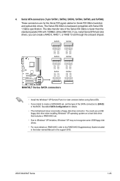
...includes a RAID/AHCI set through the onboard chipset. See 2.3.4 SATA Configuration for Serial ATA 3Gb/s hard disk and optical disk drives. 4. ASUS M4A78LT Series 1-25 Serial ATA connectors (7-pin SATA1, SATA2, SATA3, SATA4, SATA5, and SATA6) These connectors are for the Serial ATA signal ...data transfer rate of the SATA connectors to the RAID/AHCI Supplementary Guide included in the folder named Manual in the BIOS. SATA5 SATA6 GND RSATA_TXP5 RSATA_TXN5 GND RSATA_RXP5 RSATA_RXN5 GND GND RSATA_TXP6 RSATA_TXN6 GND RSATA_RXP6 RSATA_RXN6 GND SATA3 SATA4 GND RSATA_TXP4...
...includes a RAID/AHCI set through the onboard chipset. See 2.3.4 SATA Configuration for Serial ATA 3Gb/s hard disk and optical disk drives. 4. ASUS M4A78LT Series 1-25 Serial ATA connectors (7-pin SATA1, SATA2, SATA3, SATA4, SATA5, and SATA6) These connectors are for the Serial ATA signal ...data transfer rate of the SATA connectors to the RAID/AHCI Supplementary Guide included in the folder named Manual in the BIOS. SATA5 SATA6 GND RSATA_TXP5 RSATA_TXN5 GND RSATA_RXP5 RSATA_RXN5 GND GND RSATA_TXP6 RSATA_TXN6 GND RSATA_RXP6 RSATA_RXN6 GND SATA3 SATA4 GND RSATA_TXP4...
User Manual
Page 41
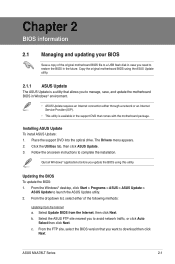
... to a USB flash disk in the future. Installing ASUS Update To install ASUS Update: 1. Click the Utilities tab, then click ASUS Update. 3. Select Update BIOS from the Internet a. c. Copy the original motherboard BIOS using this utility. ASUS M4A78LT Series 2-1 The Drivers menu appears. 2. b. Updating the BIOS To update the BIOS: 1. From the dropdown list, select either through a network or...
... to a USB flash disk in the future. Installing ASUS Update To install ASUS Update: 1. Click the Utilities tab, then click ASUS Update. 3. Select Update BIOS from the Internet a. c. Copy the original motherboard BIOS using this utility. ASUS M4A78LT Series 2-1 The Drivers menu appears. 2. b. Updating the BIOS To update the BIOS: 1. From the dropdown list, select either through a network or...

User Manual
Page 42
... onscreen instructions to complete the updating process. 2.1.2 ASUS EZ Flash 2 The ASUS EZ Flash 2 feature allows you start using this utility, download the latest BIOS file from a BIOS file a. Press to enable it. ASUSTek EZ Flash 2 BIOS ROM Utility V3.44 FLASH TYPE: EON 25P/F80 Current ROM BOARD: M4A78LT VER: 0307 (H:00 B:04) DATE: 01...
... onscreen instructions to complete the updating process. 2.1.2 ASUS EZ Flash 2 The ASUS EZ Flash 2 feature allows you start using this utility, download the latest BIOS file from a BIOS file a. Press to enable it. ASUSTek EZ Flash 2 BIOS ROM Utility V3.44 FLASH TYPE: EON 25P/F80 Current ROM BOARD: M4A78LT VER: 0307 (H:00 B:04) DATE: 01...
User Manual
Page 43
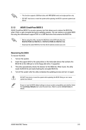
... in the USB flash drive into M4A78LT.ROM (for M4A78LT) or M478LTLE.ROM (for M4A78LT LE). • Download the latest BIOS file from the ASUS website at www.asus.com. DO NOT shut down or reset the system while updating the BIOS to prevent system boot failure! 2.1.3 ASUS CrashFree BIOS 3 ASUS CrashFree BIOS 3 is an auto recovery tool that contains the...
... in the USB flash drive into M4A78LT.ROM (for M4A78LT) or M478LTLE.ROM (for M4A78LT LE). • Download the latest BIOS file from the ASUS website at www.asus.com. DO NOT shut down or reset the system while updating the BIOS to prevent system boot failure! 2.1.3 ASUS CrashFree BIOS 3 ASUS CrashFree BIOS 3 is an auto recovery tool that contains the...

User Manual
Page 44
... in using the first two options. If you in this motherboard apply to most conditions to ensure optimum performance. 2.2 BIOS setup program Use the BIOS Setup program to update the BIOS or configure its routines. Entering BIOS Setup at startup To enter BIOS Setup at www.asus.com to download the latest BIOS file for reference only.
... in using the first two options. If you in this motherboard apply to most conditions to ensure optimum performance. 2.2 BIOS setup program Use the BIOS Setup program to update the BIOS or configure its routines. Entering BIOS Setup at startup To enter BIOS Setup at www.asus.com to download the latest BIOS file for reference only.

User Manual
Page 45
... corner of a menu screen are the navigation keys for special functions Exit For selecting the exit options and loading default settings. ASUS M4A78LT Series 2-5 Some of the screen has the following main items: Main For changing the basic system configuration Advanced For changing the ...to configure system Time. Select Screen Select Item +- Use the navigation keys to select a field. 2.2.1 BIOS menu screen Menu items Menu bar Configuration fields Main Advanced Power M4A78LT BIOS Setup Boot Tools Exit Main Settings System Time [16:34:30] System Date [Tue 01/11/2011]...
... corner of a menu screen are the navigation keys for special functions Exit For selecting the exit options and loading default settings. ASUS M4A78LT Series 2-5 Some of the screen has the following main items: Main For changing the basic system configuration Advanced For changing the ...to configure system Time. Select Screen Select Item +- Use the navigation keys to select a field. 2.2.1 BIOS menu screen Menu items Menu bar Configuration fields Main Advanced Power M4A78LT BIOS Setup Boot Tools Exit Main Settings System Time [16:34:30] System Date [Tue 01/11/2011]...

User Manual
Page 46
... To display the submenu, select the item and press . 2.2.6 Configuration fields These fields show the values for that menu. Main Advanced M4A78LT BIOS Setup Power Boot Tools Exit Power Settings Suspend Mode ACPI 2.0 Support ACPI APIC support APM Configuration HW Monitor Configuration Anti Surge Support [Auto...ly S3 only Auto Version 0307 Use [ENTER], [TAB] or [SHIFT-TAB] to display a list of the selected item. 2-6 Chapter 2: BIOS information You cannot select an item that is a brief description of options. To change the value of a field, select it then press to select...
... To display the submenu, select the item and press . 2.2.6 Configuration fields These fields show the values for that menu. Main Advanced M4A78LT BIOS Setup Power Boot Tools Exit Power Settings Suspend Mode ACPI 2.0 Support ACPI APIC support APM Configuration HW Monitor Configuration Anti Surge Support [Auto...ly S3 only Auto Version 0307 Use [ENTER], [TAB] or [SHIFT-TAB] to display a list of the selected item. 2-6 Chapter 2: BIOS information You cannot select an item that is a brief description of options. To change the value of a field, select it then press to select...

User Manual
Page 47
... navigate through them. Select Screen Select Item +- ASUS M4A78LT Series 2-7 Change Field Tab Select Field F1 General Help F10 Save and Exit ESC Exit v02.61 (C)Copyright 1985-2011, American Megatrends, Inc. 2.3.1 System Time [xx:xx:xx] Allows you to select a field. Refer to section 2.2.1 BIOS menu screen for information on the menu...
... navigate through them. Select Screen Select Item +- ASUS M4A78LT Series 2-7 Change Field Tab Select Field F1 General Help F10 Save and Exit ESC Exit v02.61 (C)Copyright 1985-2011, American Megatrends, Inc. 2.3.1 System Time [xx:xx:xx] Allows you to select a field. Refer to section 2.2.1 BIOS menu screen for information on the menu...

User Manual
Page 48
... [0] [1] [2] [3] [4] DMA Mode [Auto] Selects the DMA mode. 2.3.3 Primary IDE Master/Slave, SATA 1/2/3/4/5/6 While entering Setup, the BIOS automatically detects the presence of IDE drive. When this item is installed in the Primary IDE Master/Slave menus. Configuration options: [Auto] SMART ... [Enabled] 32Bit Data Transfer [Enabled] Enables or disables 32-bit data transfer. Configuration options: [Disabled] [Enabled] 2-8 Chapter 2: BIOS information When this item is set to [Auto], the data transfer from and to display the IDE/SATA device information. Type [Auto]...
... [0] [1] [2] [3] [4] DMA Mode [Auto] Selects the DMA mode. 2.3.3 Primary IDE Master/Slave, SATA 1/2/3/4/5/6 While entering Setup, the BIOS automatically detects the presence of IDE drive. When this item is installed in the Primary IDE Master/Slave menus. Configuration options: [Auto] SMART ... [Enabled] 32Bit Data Transfer [Enabled] Enables or disables 32-bit data transfer. Configuration options: [Disabled] [Enabled] 2-8 Chapter 2: BIOS information When this item is set to [Auto], the data transfer from and to display the IDE/SATA device information. Type [Auto]...


