
User Manual
Page 4
... panel connectors 2-21 2.7.2 Internal connectors 2-22 Chapter 3: Powering up 3.1 Starting up for the first time 3-1 3.2 Powering off the computer 3-2 3.2.1 Using the OS shut down function 3-2 3.2.2 Using the dual function power switch 3-2 Chapter 4: BIOS setup 4.1 Managing and updating your BIOS 4-1 4.1.1 Creating a bootable floppy disk 4-1 4.1.2 AFUDOS utility 4-2 4.1.3 ASUS CrashFree BIOS 2 Utility 4-5 4.1.4 ASUS Update utility 4-7 4.2 BIOS...
... panel connectors 2-21 2.7.2 Internal connectors 2-22 Chapter 3: Powering up 3.1 Starting up for the first time 3-1 3.2 Powering off the computer 3-2 3.2.1 Using the OS shut down function 3-2 3.2.2 Using the dual function power switch 3-2 Chapter 4: BIOS setup 4.1 Managing and updating your BIOS 4-1 4.1.1 Creating a bootable floppy disk 4-1 4.1.2 AFUDOS utility 4-2 4.1.3 ASUS CrashFree BIOS 2 Utility 4-5 4.1.4 ASUS Update utility 4-7 4.2 BIOS...

User Manual
Page 11
M2N-LR specifications summary Internal connectors 3 x USB 2.0 connectors support six additional USB 2.0 ports 1 x Floppy disk drive connector 1 x IDE connector for two devices 6 x Serial ATA connectors 10 x Serial ATA connectors (M2N-LR/SATA model only) 2 x CPU fan connectors 2 x Front fan connectors 2 x Rear fan connectors 1 x 24-pin ATX power ...Power requirement ATX power supply with 24-pin and 4-pin 12V plugs ATX 12V 2.0 compliant Support CD contents Device drivers ASUS Update Utility ASUS Server Web-Based Management (ASWM) Form factor ATX form factor: 12 in x 9.6 in (30.5 cm x 24...
M2N-LR specifications summary Internal connectors 3 x USB 2.0 connectors support six additional USB 2.0 ports 1 x Floppy disk drive connector 1 x IDE connector for two devices 6 x Serial ATA connectors 10 x Serial ATA connectors (M2N-LR/SATA model only) 2 x CPU fan connectors 2 x Front fan connectors 2 x Rear fan connectors 1 x 24-pin ATX power ...Power requirement ATX power supply with 24-pin and 4-pin 12V plugs ATX 12V 2.0 compliant Support CD contents Device drivers ASUS Update Utility ASUS Server Web-Based Management (ASWM) Form factor ATX form factor: 12 in x 9.6 in (30.5 cm x 24...

User Manual
Page 25
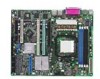
... 2: Hardware information Power Supply SMBus connector (5-pin PSUSMB1) 10. System panel auxiliary connector (20-pin AUX_PANEL1) 11. ATX power connectors (24-pin ATXPWR1, 4-pin ATX12V) 9. Internal connectors 1. Serial ATA connectors (7-pin SATA1, SATA2, SATA3 SATA4, SATA5, SATA6) 4. Serial port connector (10-1 pin COM2) 8. Floppy disk drive connector (34-1 pin FLOPPY) 2. IDE...
... 2: Hardware information Power Supply SMBus connector (5-pin PSUSMB1) 10. System panel auxiliary connector (20-pin AUX_PANEL1) 11. ATX power connectors (24-pin ATXPWR1, 4-pin ATX12V) 9. Internal connectors 1. Serial ATA connectors (7-pin SATA1, SATA2, SATA3 SATA4, SATA5, SATA6) 4. Serial port connector (10-1 pin COM2) 8. Floppy disk drive connector (34-1 pin FLOPPY) 2. IDE...

User Manual
Page 41
... The onboard IDE connector is for the Ultra DMA 133/100/66 signal cable. M2N-LR/SATA ® FLOPPY1 PIN 1 NOTE: Orient the red markings on the IDE ribbon cable to PIN 1. M2N-LR/SATA Floppy Disk Drive Connector 2. Floppy disk drive connector (34-1 pin FLOPPY) This ... the following modes to prevent incorrect cable connection when using a FDD cable with a covered Pin 5. 2.7.2 Internal connectors 1. Insert one of the floppy disk drive. M2N-LR/SATA ® PRI_IDE1 M2N-LR/SATA IDE Connector PIN 1 NOTE: Orient the red markings (usually zigzag) on the floppy ribbon cable to PIN...
... The onboard IDE connector is for the Ultra DMA 133/100/66 signal cable. M2N-LR/SATA ® FLOPPY1 PIN 1 NOTE: Orient the red markings on the IDE ribbon cable to PIN 1. M2N-LR/SATA Floppy Disk Drive Connector 2. Floppy disk drive connector (34-1 pin FLOPPY) This ... the following modes to prevent incorrect cable connection when using a FDD cable with a covered Pin 5. 2.7.2 Internal connectors 1. Insert one of the floppy disk drive. M2N-LR/SATA ® PRI_IDE1 M2N-LR/SATA IDE Connector PIN 1 NOTE: Orient the red markings (usually zigzag) on the floppy ribbon cable to PIN...