
Motherboard DIY Troubleshooting Guide
Page 1
K8N-VM Motherboard
K8N-VM Motherboard

Motherboard DIY Troubleshooting Guide
Page 3
Contents Notices vi Safety information vii k8N-VM specifications summary viii Chapter 1: Product introduction 1.1 Welcome 1-2 1.2 Package contents 1-2 1.3 Special features 1-2 1.3.1 Product highlights 1-2 1.3.2 Innovative ASUS features 1-4 1.4 Before you proceed 1-5 1.5 Motherboard overview 1-6 1.5.1 Motherboard layout 1-6 1.5.2 Placement direction 1-7 1.5.3 Screw holes 1-7 1.5.4 Layout contents 1-8 1.6 Central Processing Unit (CPU 1-9 1.7 System memory 1-11 1.7.1 Overview 1-11 1.7.2 Memory configurations 1-11 1.7.3 Installing a DIMM 1-14...
Contents Notices vi Safety information vii k8N-VM specifications summary viii Chapter 1: Product introduction 1.1 Welcome 1-2 1.2 Package contents 1-2 1.3 Special features 1-2 1.3.1 Product highlights 1-2 1.3.2 Innovative ASUS features 1-4 1.4 Before you proceed 1-5 1.5 Motherboard overview 1-6 1.5.1 Motherboard layout 1-6 1.5.2 Placement direction 1-7 1.5.3 Screw holes 1-7 1.5.4 Layout contents 1-8 1.6 Central Processing Unit (CPU 1-9 1.7 System memory 1-11 1.7.1 Overview 1-11 1.7.2 Memory configurations 1-11 1.7.3 Installing a DIMM 1-14...

Motherboard DIY Troubleshooting Guide
Page 7
Operation safety • Before installing the motherboard and adding devices on it may become wet. • Place the product on a stable surface. • If you are not sure about the voltage of ... supply is set to the correct voltage in your dealer immediately. • To avoid short circuits, keep paper clips, screws, and staples away from the motherboard, ensure that the product (electrical and electronic equipment) should not be placed in any damage, contact your area. If possible, disconnect all the manuals that...
Operation safety • Before installing the motherboard and adding devices on it may become wet. • Place the product on a stable surface. • If you are not sure about the voltage of ... supply is set to the correct voltage in your dealer immediately. • To avoid short circuits, keep paper clips, screws, and staples away from the motherboard, ensure that the product (electrical and electronic equipment) should not be placed in any damage, contact your area. If possible, disconnect all the manuals that...

Motherboard DIY Troubleshooting Guide
Page 11
This chapter describes the motherboard features and the new technologies it supports. 1Product introduction
This chapter describes the motherboard features and the new technologies it supports. 1Product introduction
Motherboard DIY Troubleshooting Guide
Page 12
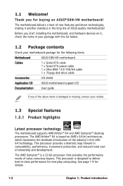
..., which represents the landmark introduction of the industryʼs first x8664 technology. Before you for everyday computing. The motherboard delivers a host of value-conscious buyers. See page 1-9 for the following items. Motherboard ASUS K8N-VM motherboard Cables 1 x Serial ATA cable 1 x Serial ATA power cable 1 x Ultra DMA 133/100/66 cable 1 x Floppy disk drive cable Accessories...
..., which represents the landmark introduction of the industryʼs first x8664 technology. Before you for everyday computing. The motherboard delivers a host of value-conscious buyers. See page 1-9 for the following items. Motherboard ASUS K8N-VM motherboard Cables 1 x Serial ATA cable 1 x Serial ATA power cable 1 x Ultra DMA 133/100/66 cable 1 x Floppy disk drive cable Accessories...
Motherboard DIY Troubleshooting Guide
Page 13
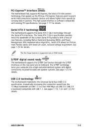
... turns your computer into a high-end entertainment system with lower pin count, reduced voltage requirement. ASUS K8N-VM 1-3 See page 1-17 for details. Serial ATA II technology The motherboard supports the Serial ATA 3 Gb/s technology through the S/PDIF interfaces on USB 2.0. PCI Express ... a host of new features, including Native Command Queueing (NCQ), and Power Management (PM) Implementation Algorithm. USB 2.0 technology The motherboard implements the Universal Serial Bus (USB) 2.0 specification, dramatically increasing the connection speed from the 12 Mbps bandwidth on USB...
... turns your computer into a high-end entertainment system with lower pin count, reduced voltage requirement. ASUS K8N-VM 1-3 See page 1-17 for details. Serial ATA II technology The motherboard supports the Serial ATA 3 Gb/s technology through the S/PDIF interfaces on USB 2.0. PCI Express ... a host of new features, including Native Command Queueing (NCQ), and Power Management (PM) Implementation Algorithm. USB 2.0 technology The motherboard implements the Universal Serial Bus (USB) 2.0 specification, dramatically increasing the connection speed from the 12 Mbps bandwidth on USB...
Motherboard DIY Troubleshooting Guide
Page 14
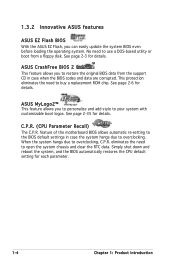
...feature allows you can easily update the system BIOS even before loading the operating system. 1.3.2 Innovative ASUS features ASUS EZ Flash BIOS With the ASUS EZ Flash, you to restore the original BIOS data from a floppy disk. See ...each parameter. 1-4 Chapter 1: Product introduction When the system hangs due to your system with customizable boot logos. ASUS MyLogo2™ This feature allows you to personalize and add style to overclocking, C.P.R. No need to use a... and data are corrupted. feature of the motherboard BIOS allows automatic re-setting to overclocking.
...feature allows you can easily update the system BIOS even before loading the operating system. 1.3.2 Innovative ASUS features ASUS EZ Flash BIOS With the ASUS EZ Flash, you to restore the original BIOS data from a floppy disk. See ...each parameter. 1-4 Chapter 1: Product introduction When the system hangs due to your system with customizable boot logos. ASUS MyLogo2™ This feature allows you to personalize and add style to overclocking, C.P.R. No need to use a... and data are corrupted. feature of the motherboard BIOS allows automatic re-setting to overclocking.
Motherboard DIY Troubleshooting Guide
Page 15
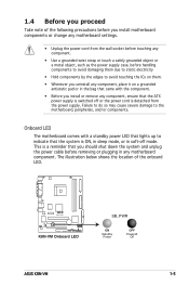
R K8N-VM K8N-VM Onboard LED SB_PWR ON Standby Power OFF Powered Off ASUS K8N-VM 1-5 The illustration below shows the location of the following precautions before you install motherboard components or change any motherboard settings. • Unplug the power cord from the power supply. This is a reminder that you ...8226; Hold components by the edges to avoid touching the ICs on them. • Whenever you uninstall any motherboard component. Onboard LED The motherboard comes with the component. • Before you should shut down the system and unplug the power cable before ...
R K8N-VM K8N-VM Onboard LED SB_PWR ON Standby Power OFF Powered Off ASUS K8N-VM 1-5 The illustration below shows the location of the following precautions before you install motherboard components or change any motherboard settings. • Unplug the power cord from the power supply. This is a reminder that you ...8226; Hold components by the edges to avoid touching the ICs on them. • Whenever you uninstall any motherboard component. Onboard LED The motherboard comes with the component. • Before you should shut down the system and unplug the power cable before ...

Motherboard DIY Troubleshooting Guide
Page 16
1.5 Motherboard overview 1.5.1 Motherboard layout 19.3cm (7.6in) PS/2 T: Mouse KBPWR B: Keyboard COM1 ATX12V CPU_FAN EATXPWR DDR DIMM1 (64 bit, 184-pin module) DDR DIMM2 (64 bit, 184-pin ... USBPW1234 Bottom: USB3 USB4 Top: RJ-45 Top:Line In Center:Line Out Below:Mic In Realtek 4Mb Flash ROM PCIEX1_1 Super I/O nVidia GeForce 6100 R K8N-VM PCIEX16 CD AAFP Audio SPDIF_OUT PCI1 SB_PWR PCI2 FLOPPY CR2032 3V Lithium Cell CMOS Powe nVidia nForce 410 SATA2 USBPW5678 USB56 USB78 SATA1 CLRTC PANEL...
1.5 Motherboard overview 1.5.1 Motherboard layout 19.3cm (7.6in) PS/2 T: Mouse KBPWR B: Keyboard COM1 ATX12V CPU_FAN EATXPWR DDR DIMM1 (64 bit, 184-pin module) DDR DIMM2 (64 bit, 184-pin ... USBPW1234 Bottom: USB3 USB4 Top: RJ-45 Top:Line In Center:Line Out Below:Mic In Realtek 4Mb Flash ROM PCIEX1_1 Super I/O nVidia GeForce 6100 R K8N-VM PCIEX16 CD AAFP Audio SPDIF_OUT PCI1 SB_PWR PCI2 FLOPPY CR2032 3V Lithium Cell CMOS Powe nVidia nForce 410 SATA2 USBPW5678 USB56 USB78 SATA1 CLRTC PANEL...

Motherboard DIY Troubleshooting Guide
Page 17
Doing so can damage the motherboard. Place this side towards the rear of the chassis as indicated in the image below. 1.5.3 Screw holes Place six (6) screws into the chassis in the correct orientation. The edge with external ports goes to the chassis. Do not overtighten the screws! 1.5.2 Placement direction When installing the motherboard, make sure that you place it into the holes indicated by circles to secure the motherboard to the rear part of the chassis R K8N-VM ASUS K8N-VM 1-7
Doing so can damage the motherboard. Place this side towards the rear of the chassis as indicated in the image below. 1.5.3 Screw holes Place six (6) screws into the chassis in the correct orientation. The edge with external ports goes to the chassis. Do not overtighten the screws! 1.5.2 Placement direction When installing the motherboard, make sure that you place it into the holes indicated by circles to secure the motherboard to the rear part of the chassis R K8N-VM ASUS K8N-VM 1-7
Motherboard DIY Troubleshooting Guide
Page 19
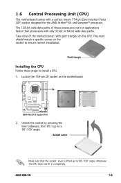
R K8N-VM K8N-VM CPU Socket 754 2. Unlock the socket by pressing the lever sideways, then lift it up to a 90°-100° angle. ASUS K8N-VM 1-9 Socket Lever Make sure that the socket lever is lifted up to 90°-100° angle, otherwise the CPU does not fit in ...completely. 1.6 Central Processing Unit (CPU) The motherboard comes with gold triangle) on the CPU. This mark should...
R K8N-VM K8N-VM CPU Socket 754 2. Unlock the socket by pressing the lever sideways, then lift it up to a 90°-100° angle. ASUS K8N-VM 1-9 Socket Lever Make sure that the socket lever is lifted up to 90°-100° angle, otherwise the CPU does not fit in ...completely. 1.6 Central Processing Unit (CPU) The motherboard comes with gold triangle) on the CPU. This mark should...

Motherboard DIY Troubleshooting Guide
Page 20
... connector on the side tab to indicate that it fits in place. The lever clicks on the motherboard. Carefully insert the CPU into the socket to connect the CPU fan connector! CPU_FAN R K8N-VM K8N-VM CPU Fan Connector Do not forget to prevent bending the pins and damaging the CPU! 5. Position the CPU...
... connector on the side tab to indicate that it fits in place. The lever clicks on the motherboard. Carefully insert the CPU into the socket to connect the CPU fan connector! CPU_FAN R K8N-VM K8N-VM CPU Fan Connector Do not forget to prevent bending the pins and damaging the CPU! 5. Position the CPU...
Motherboard DIY Troubleshooting Guide
Page 21
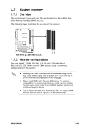
...any of the sockets: R K8N-VM K8N-VM 184-pin DDR DIMM Sockets 1.7.2 Memory configurations You may install 128 MB, 256 MB, 512 MB, and 1 GB unbuffered ECC/non-ECC DDR DIMMs into the DIMM sockets using the memory configurations in this motherboard does not support DIMM modules ...with less than the recommended configurations may cause memory sizing error or system boot failure. DIMM1 DIMM2 ASUS K8N-VM 1-11 1.7 System memory 1.7.1 Overview The motherboard comes with the same CAS latency. Refer to 128 Mb memory chips. For optimum compatibility, it is recommended that ...
...any of the sockets: R K8N-VM K8N-VM 184-pin DDR DIMM Sockets 1.7.2 Memory configurations You may install 128 MB, 256 MB, 512 MB, and 1 GB unbuffered ECC/non-ECC DDR DIMMs into the DIMM sockets using the memory configurations in this motherboard does not support DIMM modules ...with less than the recommended configurations may cause memory sizing error or system boot failure. DIMM1 DIMM2 ASUS K8N-VM 1-11 1.7 System memory 1.7.1 Overview The motherboard comes with the same CAS latency. Refer to 128 Mb memory chips. For optimum compatibility, it is recommended that ...

Motherboard DIY Troubleshooting Guide
Page 24
... fingers when pressing the retaining clips. Unlock a DIMM socket by pressing the retaining clips outward. 2. Simultaneously press the retaining clips outward to both the motherboard and the components. 1. DO NOT force a DIMM into the socket until the retaining clips snap back in place and the DIMM is keyed with extra...
... fingers when pressing the retaining clips. Unlock a DIMM socket by pressing the retaining clips outward. 2. Simultaneously press the retaining clips outward to both the motherboard and the components. 1. DO NOT force a DIMM into the socket until the retaining clips snap back in place and the DIMM is keyed with extra...

Motherboard DIY Troubleshooting Guide
Page 25
...an IRQ to the chassis with the screw you removed earlier. 6. ASUS K8N-VM 1-15 The following sub-sections describe the slots and the expansion cards that you intend to use . 4. Remove the system unit cover (if your motherboard is completely seated on the next page. 3. Turn on BIOS setup...the power cord before adding or removing expansion cards. 1.8 Expansion slots In the future, you may cause you physical injury and damage motherboard components. 1.8.1 Installing an expansion card To install an expansion card: 1. Make sure to install expansion cards. Remove the bracket opposite the...
...an IRQ to the chassis with the screw you removed earlier. 6. ASUS K8N-VM 1-15 The following sub-sections describe the slots and the expansion cards that you intend to use . 4. Remove the system unit cover (if your motherboard is completely seated on the next page. 3. Turn on BIOS setup...the power cord before adding or removing expansion cards. 1.8 Expansion slots In the future, you may cause you physical injury and damage motherboard components. 1.8.1 Installing an expansion card To install an expansion card: 1. Make sure to install expansion cards. Remove the bracket opposite the...

Motherboard DIY Troubleshooting Guide
Page 26
...* IRQ holder for PCI steering* PS/2 Compatible Mouse Port* Numeric Data Processor Primary IDE Channel Secondary IDE Channel * These IRQs are usually available for this motherboard PCI slot 1 PCI slot 2 A B C D - -
...* IRQ holder for PCI steering* PS/2 Compatible Mouse Port* Numeric Data Processor Primary IDE Channel Secondary IDE Channel * These IRQs are usually available for this motherboard PCI slot 1 PCI slot 2 A B C D - -
Motherboard DIY Troubleshooting Guide
Page 27
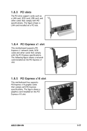
...;gure shows a LAN card installed on a PCI slot. 1.8.4 PCI Express x1 slot This motherboard supports PCI Express x1 network cards, SCSI cards and other cards that comply with PCI specifications. ASUS K8N-VM 1-17 The figure shows a graphics card installed on the PCI Express x1 slot. ...1.8.5 PCI Express x16 slot This motherboard has supports PCI Express x16 graphic cards that comply with PCI Express speci&#...
...;gure shows a LAN card installed on a PCI slot. 1.8.4 PCI Express x1 slot This motherboard supports PCI Express x1 network cards, SCSI cards and other cards that comply with PCI specifications. ASUS K8N-VM 1-17 The figure shows a graphics card installed on the PCI Express x1 slot. ...1.8.5 PCI Express x16 slot This motherboard has supports PCI Express x16 graphic cards that comply with PCI Express speci&#...
Motherboard DIY Troubleshooting Guide
Page 33
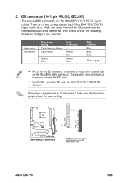
...gure your devices. Single device Two devices Drive jumper setting Cable-Select or Master Cable-Select Master Slave Mode of the following modes to the motherboardʼs IDE connector, then select one of device(s) Master Slave Master Slave Cable connector Black Black Gray Black or gray • Pin 20... zigzag) on the IDE ribbon cable to match the covered hole on each Ultra DMA 133/100/66 signal cable: blue, black, and gray. ASUS K8N-VM 1-23 There are for Ultra DMA 133/100/66 IDE devices. IDE connectors (40-1 pin PRI_IDE, SEC_IDE) The onboard IDE connectors are three connectors...
...gure your devices. Single device Two devices Drive jumper setting Cable-Select or Master Cable-Select Master Slave Mode of the following modes to the motherboardʼs IDE connector, then select one of device(s) Master Slave Master Slave Cable connector Black Black Gray Black or gray • Pin 20... zigzag) on the IDE ribbon cable to match the covered hole on each Ultra DMA 133/100/66 signal cable: blue, black, and gray. ASUS K8N-VM 1-23 There are for Ultra DMA 133/100/66 IDE devices. IDE connectors (40-1 pin PRI_IDE, SEC_IDE) The onboard IDE connectors are three connectors...
Motherboard DIY Troubleshooting Guide
Page 36
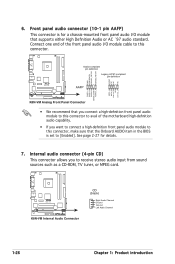
... this connector to avail of the motherboard high-definition audio capability. • If you to [Enabled]. See page 2-27 for a chassis-mounted front panel audio I /O module cable to this connector, make sure that the Onboard AUDIO item in the BIOS is for details. 7. 6. R K8N-VM GND PRESENCE# SENSE1_RETUR SENSE2_RETUR Azalia-compliant...
... this connector to avail of the motherboard high-definition audio capability. • If you to [Enabled]. See page 2-27 for a chassis-mounted front panel audio I /O module cable to this connector, make sure that the Onboard AUDIO item in the BIOS is for details. 7. 6. R K8N-VM GND PRESENCE# SENSE1_RETUR SENSE2_RETUR Azalia-compliant...
Motherboard DIY Troubleshooting Guide
Page 40
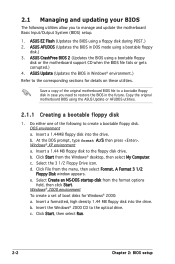
... a. Copy the original motherboard BIOS using a floppy disk during POST.) 2. Windows® 2000 environment To create a set of boot disks for details on these utilities. b. Click Start, then select Run. 2-2 Chapter 2: BIOS setup ASUS EZ Flash (Updates the BIOS using the ASUS Update or AFUDOS utilities.... Insert a formatted, high density 1.44 MB floppy disk into the drive. ASUS CrashFree BIOS 2 (Updates the BIOS using a bootable floppy disk.) 3. Do either one of the original motherboard BIOS file to a bootable floppy disk in case you to manage and...
... a. Copy the original motherboard BIOS using a floppy disk during POST.) 2. Windows® 2000 environment To create a set of boot disks for details on these utilities. b. Click Start, then select Run. 2-2 Chapter 2: BIOS setup ASUS EZ Flash (Updates the BIOS using the ASUS Update or AFUDOS utilities.... Insert a formatted, high density 1.44 MB floppy disk into the drive. ASUS CrashFree BIOS 2 (Updates the BIOS using a bootable floppy disk.) 3. Do either one of the original motherboard BIOS file to a bootable floppy disk in case you to manage and...


