
K8N-E User's Manual
Page 1
Motherboard K8N-E User Guide
Motherboard K8N-E User Guide

K8N-E User's Manual
Page 3
... vi Safety information vii About this guide viii Conventions used in this guide viii Typography viii K8N-E specifications summary ix Chapter 1: Product introduction 1.1 Welcome 1-2 1.2 Package contents 1-2 1.3 Special features 1-3 1.3.1 Product Highlights 1-3 1.3.2 Unique ASUS features 1-4 1.4 Before you proceed 1-5 1.5 Motherboard overview 1-6 1.5.1 Motherboard layout 1-6 1.5.2 Placement direction 1-7 1.5.3 Screw holes 1-7 1.6 Central Processing Unit (CPU 1-8 1.6.1 Overview 1-8 1.6.2 Installing the CPU 1-9 1.7 System memory...
... vi Safety information vii About this guide viii Conventions used in this guide viii Typography viii K8N-E specifications summary ix Chapter 1: Product introduction 1.1 Welcome 1-2 1.2 Package contents 1-2 1.3 Special features 1-3 1.3.1 Product Highlights 1-3 1.3.2 Unique ASUS features 1-4 1.4 Before you proceed 1-5 1.5 Motherboard overview 1-6 1.5.1 Motherboard layout 1-6 1.5.2 Placement direction 1-7 1.5.3 Screw holes 1-7 1.6 Central Processing Unit (CPU 1-8 1.6.1 Overview 1-8 1.6.2 Installing the CPU 1-9 1.7 System memory...

K8N-E User's Manual
Page 7
...and staples away from connectors, slots, sockets and circuitry. • Avoid dust, humidity, and temperature extremes. Operation safety • Before installing the motherboard and adding devices on it may become wet. • Place the product on a stable surface. • If you encounter technical problems with the...the power cables for the devices are unplugged before you add a device. • Before connecting or removing signal cables from the motherboard, ensure that all cables are correctly connected and the power cables are not damaged. If you detect any area where it , carefully...
...and staples away from connectors, slots, sockets and circuitry. • Avoid dust, humidity, and temperature extremes. Operation safety • Before installing the motherboard and adding devices on it may become wet. • Place the product on a stable surface. • If you encounter technical problems with the...the power cables for the devices are unplugged before you add a device. • Before connecting or removing signal cables from the motherboard, ensure that all cables are correctly connected and the power cables are not damaged. If you detect any area where it , carefully...

K8N-E User's Manual
Page 11
Chapter 1 This chapter describes the features of the layout, jumper settings, and connectors. Product introduction It includes brief descriptions of the motherboard components, and illustrations of the motherboard.
Chapter 1 This chapter describes the features of the layout, jumper settings, and connectors. Product introduction It includes brief descriptions of the motherboard components, and illustrations of the motherboard.

K8N-E User's Manual
Page 12
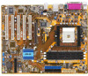
...AMD Sempron™ processor with the list below. 1.2 Package contents Check your retailer. 1-2 Chapter 1: Product introduction Before you for the following items. ASUS K8N-E motherboard ASUS motherboard support CD 1 x Ultra DMA 133/100/66 cables 1 x Serial ATA module (SATA cable + Power cable) 1 x Floppy disk cable ...I/O shield Bag of extra jumper caps User guide If any of ASUS quality motherboards! The motherboard delivers a host of new features and latest technologies making it , check the items in the long line of the above items...
...AMD Sempron™ processor with the list below. 1.2 Package contents Check your retailer. 1-2 Chapter 1: Product introduction Before you for the following items. ASUS K8N-E motherboard ASUS motherboard support CD 1 x Ultra DMA 133/100/66 cables 1 x Serial ATA module (SATA cable + Power cable) 1 x Floppy disk cable ...I/O shield Bag of extra jumper caps User guide If any of ASUS quality motherboards! The motherboard delivers a host of new features and latest technologies making it , check the items in the long line of the above items...

K8N-E User's Manual
Page 13
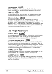
...-in RAID controller enhances hard disk performance and data backup protection without the cost of ownership and development. ASUS K8N-E 1-3 Cool 'n' Quiet!™ Technology The motherboard supports the AMD® Cool 'n' Quiet!™ Technology that spans across the IDE and Serial ATA drives... AMD Sempron™ is designed to 150 MB/s data transfer rate. 1.3 Special features 1.3.1 Product Highlights Latest processor technology The motherboard supports the AMD Athlon™ 64 and AMD Sempron™ desktop processors. This processor provides a dramatic leap forward in -class...
...-in RAID controller enhances hard disk performance and data backup protection without the cost of ownership and development. ASUS K8N-E 1-3 Cool 'n' Quiet!™ Technology The motherboard supports the AMD® Cool 'n' Quiet!™ Technology that spans across the IDE and Serial ATA drives... AMD Sempron™ is designed to 150 MB/s data transfer rate. 1.3 Special features 1.3.1 Product Highlights Latest processor technology The motherboard supports the AMD Athlon™ 64 and AMD Sempron™ desktop processors. This processor provides a dramatic leap forward in -class...
K8N-E User's Manual
Page 14
...the RTC data. When the system hangs due to eight USB 2.0 ports. feature of the motherboard BIOS allows automatic re-setting to the BIOS default settings in the motherboard allows you to personalize and add style to buy a replacement ROM chip. See page 2-6. Simply.../s. C.P.R. (CPU Parameter Recall) The C.P.R. USB 2.0 is the VGA interface specification that enables enhanced graphics performance with USB 1.1. 1.3.2 Unique ASUS features CrashFree BIOS 2 This feature allows you can easily update the system BIOS even before loading the operating system. No need to restore ...
...the RTC data. When the system hangs due to eight USB 2.0 ports. feature of the motherboard BIOS allows automatic re-setting to the BIOS default settings in the motherboard allows you to personalize and add style to buy a replacement ROM chip. See page 2-6. Simply.../s. C.P.R. (CPU Parameter Recall) The C.P.R. USB 2.0 is the VGA interface specification that enables enhanced graphics performance with USB 1.1. 1.3.2 Unique ASUS features CrashFree BIOS 2 This feature allows you can easily update the system BIOS even before loading the operating system. No need to restore ...

K8N-E User's Manual
Page 15
...place it on them. 4. 1.4 Before you proceed Take note of the onboard LED. ® K8N-E K8N-E Onboard LED SB_PWR ON Standby Power OFF Powered Off ASUS K8N-E 1-5 Before you install motherboard components or change any component, ensure that came with a stand-by the edges to static electricity.... 3. Onboard LED The motherboard comes with the component. 5. Unplug the power cord ...
...place it on them. 4. 1.4 Before you proceed Take note of the onboard LED. ® K8N-E K8N-E Onboard LED SB_PWR ON Standby Power OFF Powered Off ASUS K8N-E 1-5 Before you install motherboard components or change any component, ensure that came with a stand-by the edges to static electricity.... 3. Onboard LED The motherboard comes with the component. 5. Unplug the power cord ...
K8N-E User's Manual
Page 16
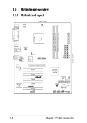
1.5 Motherboard overview 1.5.1 Motherboard layout PS/2KBMS T: Mouse B: Keyboard SPDIF_O1 ATX12V 24.5cm (9.6in) CPU_FAN ATX Power Connector DDR DIMM1 (64 bit,184-pin module) DDR DIMM2 (64 bit,... Center:Line Out Below:Mic In FP_AUDIO ALC850 SPDIF_OUT Super I/O CD AUX LAN PHY PWR_FAN SATA2 SATA1 Accelerated Graphics Port (AGP) PCI1 PCI2 R PCI3 PCI4 K8N-E PCI5 GAME nVIDIA nForce3 250Gb 4Mbit BIOS CHA_FAN USBPW56 USBPW78 FLOPPY CR2032 3V SB_PWR Lithium Cell CMOS Power USB56 USB78 CLRTC CHASSIS PANEL PRI_IDE SEC_IDE...
1.5 Motherboard overview 1.5.1 Motherboard layout PS/2KBMS T: Mouse B: Keyboard SPDIF_O1 ATX12V 24.5cm (9.6in) CPU_FAN ATX Power Connector DDR DIMM1 (64 bit,184-pin module) DDR DIMM2 (64 bit,... Center:Line Out Below:Mic In FP_AUDIO ALC850 SPDIF_OUT Super I/O CD AUX LAN PHY PWR_FAN SATA2 SATA1 Accelerated Graphics Port (AGP) PCI1 PCI2 R PCI3 PCI4 K8N-E PCI5 GAME nVIDIA nForce3 250Gb 4Mbit BIOS CHA_FAN USBPW56 USBPW78 FLOPPY CR2032 3V SB_PWR Lithium Cell CMOS Power USB56 USB78 CLRTC CHASSIS PANEL PRI_IDE SEC_IDE...

K8N-E User's Manual
Page 17
Do not overtighten the screws! Place this side towards the rear of the chassis as indicated in the correct orientation. Doing so may damage the motherboard. 1.5.2 Placement direction When installing the motherboard, make sure that you place it into the chassis in the image below. 1.5.3 Screw holes Place nine (9) screws into the holes indicated by circles to secure the motherboard to the chassis. The edge with external ports goes to the rear part of the chassis ® K8N-E ASUS K8N-E 1-7
Do not overtighten the screws! Place this side towards the rear of the chassis as indicated in the correct orientation. Doing so may damage the motherboard. 1.5.2 Placement direction When installing the motherboard, make sure that you place it into the chassis in the image below. 1.5.3 Screw holes Place nine (9) screws into the holes indicated by circles to secure the motherboard to the chassis. The edge with external ports goes to the rear part of the chassis ® K8N-E ASUS K8N-E 1-7

K8N-E User's Manual
Page 18
1.6 Central Processing Unit (CPU) 1.6.1 Overview The motherboard comes with only 32-bit or 64-bit wide data paths. ® K8N-E K8N-E CPU Socket 754 Gold Arrow Incorrect installation of these processors can run applications faster than processors with a surface mount 754-pin Zero Insertion Force (ZIF) socket designed for the AMD Athlon™ 64 and AMD Sempron™ processors. The 128-bit-wide data paths of the CPU into the socket may bend the pins and severely damage the CPU! 1-8 Chapter 1: Product introduction
1.6 Central Processing Unit (CPU) 1.6.1 Overview The motherboard comes with only 32-bit or 64-bit wide data paths. ® K8N-E K8N-E CPU Socket 754 Gold Arrow Incorrect installation of these processors can run applications faster than processors with a surface mount 754-pin Zero Insertion Force (ZIF) socket designed for the AMD Athlon™ 64 and AMD Sempron™ processors. The 128-bit-wide data paths of the CPU into the socket may bend the pins and severely damage the CPU! 1-8 Chapter 1: Product introduction

K8N-E User's Manual
Page 19
... lift it is locked. 6. ASUS K8N-E 1-9 Locate the 754-pin ZIF socket on the side tab to 90°-100° angle, otherwise the CPU does not fit in place. Socket Lever Make sure that the socket lever is in one correct orientation. The lever clicks on the motherboard. 2. DO NOT force the...
... lift it is locked. 6. ASUS K8N-E 1-9 Locate the 754-pin ZIF socket on the side tab to 90°-100° angle, otherwise the CPU does not fit in place. Socket Lever Make sure that the socket lever is in one correct orientation. The lever clicks on the motherboard. 2. DO NOT force the...

K8N-E User's Manual
Page 20
...figure illustrates the location of the memory configurations in this motherboard. 1-10 Chapter 1: Product introduction DIMM1 DIMM2 DIMM3 104 Pins 80 Pins ® K8N-E K8N-E 184-pin DDR DIMM sockets Make sure to both the motherboard and the components. 1.7.2 Memory configurations You may cause ...memory sizing error or system boot failure. Visit the ASUS website (www.asus.com) for the latest DDR 400 Qualified...
...figure illustrates the location of the memory configurations in this motherboard. 1-10 Chapter 1: Product introduction DIMM1 DIMM2 DIMM3 104 Pins 80 Pins ® K8N-E K8N-E 184-pin DDR DIMM sockets Make sure to both the motherboard and the components. 1.7.2 Memory configurations You may cause ...memory sizing error or system boot failure. Visit the ASUS website (www.asus.com) for the latest DDR 400 Qualified...

K8N-E User's Manual
Page 21
... 512MB 256MB 512MB 256MB 512MB 512MB 256MB 512MB 256MB 512MB 256MB 256MB 256MB 512MB 256MB 512MB 256MB 512MB 256MB 512MB 256MB 512MB ASUS K8N-E 1-11 Single Side Single Side Single Side Single Side Double Side Double Side Double Side Double Side Single Side Single Side ...200 DDR Qualified Vendors List The following table lists the PC3200 (DDR400) memory modules that have been tested and qualified for this motherboard. DIMM Vendor Chip Number KINGSTON KINGSTON KINGSTON KINGSTON KINGSTON KINGSTON KINGSTON KINGSTON KINGSTON SAMSUNG SAMSUNG SAMSUNG SAMSUNG SAMSUNG SAMSUNG Hynix Hynix MICRON...
... 512MB 256MB 512MB 256MB 512MB 512MB 256MB 512MB 256MB 512MB 256MB 256MB 256MB 512MB 256MB 512MB 256MB 512MB 256MB 512MB 256MB 512MB ASUS K8N-E 1-11 Single Side Single Side Single Side Single Side Double Side Double Side Double Side Double Side Single Side Single Side ...200 DDR Qualified Vendors List The following table lists the PC3200 (DDR400) memory modules that have been tested and qualified for this motherboard. DIMM Vendor Chip Number KINGSTON KINGSTON KINGSTON KINGSTON KINGSTON KINGSTON KINGSTON KINGSTON KINGSTON SAMSUNG SAMSUNG SAMSUNG SAMSUNG SAMSUNG SAMSUNG Hynix Hynix MICRON...

K8N-E User's Manual
Page 23
used When using PCI cards on shared slots, ensure that the drivers support "Share IRQ" or that comply with PCI specifications. INT B - used - - INT E - - - - - ASUS K8N-E 1-13 shared - - - - shared - - - INT C - - shared - INT D - - - Otherwise, conflicts will arise between the two PCI groups, making the system unstable and the card inoperable... a LAN card, SCSI card, USB card, and other cards that the cards do not need IRQ assignments. 1.8.2 IRQ assignments for this motherboard PCI slot 1 PCI slot 2 PCI slot 3 PCI slot 4 PCI slot 5 AGP slot INT A shared - - -
used When using PCI cards on shared slots, ensure that the drivers support "Share IRQ" or that comply with PCI specifications. INT B - used - - INT E - - - - - ASUS K8N-E 1-13 shared - - - - shared - - - INT C - - shared - INT D - - - Otherwise, conflicts will arise between the two PCI groups, making the system unstable and the card inoperable... a LAN card, SCSI card, USB card, and other cards that the cards do not need IRQ assignments. 1.8.2 IRQ assignments for this motherboard PCI slot 1 PCI slot 2 PCI slot 3 PCI slot 4 PCI slot 5 AGP slot INT A shared - - -

K8N-E User's Manual
Page 24
1.8.4 AGP slot The Accelerated Graphics Port (AGP) slot supports AGP 8X/4X (+1.5V) cards. Note the notches on the card golden fingers to ensure that you buy an AGP card, make sure that they fit the AGP slot on the motherboard. Install only +1.5V AGP cards. ® K8N-E Keyed for 1.5v K8N-E Accelerated Graphics Port (AGP) If installing the ATi 9500 or 9700 Pro Series VGA cards, use only the card version PN xxx-xxxxx-30 or later, for one with +1.5V specification. When you ask for optimum performance and overclocking stability. 1-14 Chapter 1: Product introduction
1.8.4 AGP slot The Accelerated Graphics Port (AGP) slot supports AGP 8X/4X (+1.5V) cards. Note the notches on the card golden fingers to ensure that you buy an AGP card, make sure that they fit the AGP slot on the motherboard. Install only +1.5V AGP cards. ® K8N-E Keyed for 1.5v K8N-E Accelerated Graphics Port (AGP) If installing the ATi 9500 or 9700 Pro Series VGA cards, use only the card version PN xxx-xxxxx-30 or later, for one with +1.5V specification. When you ask for optimum performance and overclocking stability. 1-14 Chapter 1: Product introduction

K8N-E User's Manual
Page 27
Line In port. This Line In (light blue) port connects a tape player or other devices. 3. Microphone port. 1.10 Connectors This section describes and illustrates the motherboard rear panel and internal connectors. 1.10.1 Rear panel connectors 1 2 3 4 5 6 11 10 9 8 7 1. This green 6-pin connector is for a PS/2 mouse. 2....Pink Line In Line Out Mic In Rear Speaker Out Front Speaker Out Mic In Rear Speaker Out Front Speaker Out Bass/Center Speaker ASUS K8N-E 1-17 This Mic (pink) port connects a microphone. PS/2 mouse port. LAN port LED indications ACT/LINK LED SPEED LED ...
Line In port. This Line In (light blue) port connects a tape player or other devices. 3. Microphone port. 1.10 Connectors This section describes and illustrates the motherboard rear panel and internal connectors. 1.10.1 Rear panel connectors 1 2 3 4 5 6 11 10 9 8 7 1. This green 6-pin connector is for a PS/2 mouse. 2....Pink Line In Line Out Mic In Rear Speaker Out Front Speaker Out Mic In Rear Speaker Out Front Speaker Out Bass/Center Speaker ASUS K8N-E 1-17 This Mic (pink) port connects a microphone. PS/2 mouse port. LAN port LED indications ACT/LINK LED SPEED LED ...

K8N-E User's Manual
Page 29
K8N-E Floppy disk drive connector 3. Serial ATA connectors (7-pin SATA1, SATA2) These next generation connectors support the thin Serial ATA cables for primary internal storage devices. 2. After connecting one end to the motherboard, connect the other end to the floppy drive. (Pin 5 is removed to prevent incorrect insertion ...133MB/s (Ultra ATA/133).These connectors support two Serial ATA hard disk drives that you can combine with pin 5 plug). ® K8N-E FLOPPY PIN 1 NOTE: Orient the red markings on the floppy ribbon cable to configure a RAID set through the built-in RAID controller. &#...
K8N-E Floppy disk drive connector 3. Serial ATA connectors (7-pin SATA1, SATA2) These next generation connectors support the thin Serial ATA cables for primary internal storage devices. 2. After connecting one end to the motherboard, connect the other end to the floppy drive. (Pin 5 is removed to prevent incorrect insertion ...133MB/s (Ultra ATA/133).These connectors support two Serial ATA hard disk drives that you can combine with pin 5 plug). ® K8N-E FLOPPY PIN 1 NOTE: Orient the red markings on the floppy ribbon cable to configure a RAID set through the built-in RAID controller. &#...

K8N-E User's Manual
Page 30
The minimum recommended wattage is inadequate. ATX12V GND +12V DC GND +12V DC ® K8N-E K8N-E ATX power connectors ATXPWR Pin 1 +12.0VDC +5VSB PWR_OK COM +5.0VDC COM +5.0VDC COM +3.3VDC +3.3VDC +5.0VDC +5.0VDC -5.0VDC COM COM COM PS_ON# COM -12.... sources such as a CD-ROM, TV tuner, or MPEG card. ® K8N-E CD (Black) AUX (White) Right Audio Channel Ground Left Audio Channel K8N-E Internal audio connectors 1-20 Chapter 1: Product introduction 4. In addition to the 20-pin ATX power connector, this motherboard requires that your ATX 12V power supply can provide 8A on...
The minimum recommended wattage is inadequate. ATX12V GND +12V DC GND +12V DC ® K8N-E K8N-E ATX power connectors ATXPWR Pin 1 +12.0VDC +5VSB PWR_OK COM +5.0VDC COM +5.0VDC COM +3.3VDC +3.3VDC +5.0VDC +5.0VDC -5.0VDC COM COM COM PS_ON# COM -12.... sources such as a CD-ROM, TV tuner, or MPEG card. ® K8N-E CD (Black) AUX (White) Right Audio Channel Ground Left Audio Channel K8N-E Internal audio connectors 1-20 Chapter 1: Product introduction 4. In addition to the 20-pin ATX power connector, this motherboard requires that your ATX 12V power supply can provide 8A on...

K8N-E User's Manual
Page 31
Do not forget to connect the fan cables to the fan connectors on the fan connectors! DO NOT place jumper caps on the motherboard, making sure that the black wire of each cable matches the ground pin of sufficient air flow within the system may install the USB ... Connect the USB cable of 1A~2.22A (26.64W max.) at +12V. CPU_FAN Rotation +12V GND ® K8N-E K8N-E Fan connectors PWR_FAN GND +12V Rotation CHA_FAN Rotation +12V GND 7. You may damage the motherboard components. ASUS K8N-E USB+5V USB_P7USB_P7+ GND 1-21 USB header (10-1 pin USB56, USB78) If the USB ports on the ...
Do not forget to connect the fan cables to the fan connectors on the fan connectors! DO NOT place jumper caps on the motherboard, making sure that the black wire of each cable matches the ground pin of sufficient air flow within the system may install the USB ... Connect the USB cable of 1A~2.22A (26.64W max.) at +12V. CPU_FAN Rotation +12V GND ® K8N-E K8N-E Fan connectors PWR_FAN GND +12V Rotation CHA_FAN Rotation +12V GND 7. You may damage the motherboard components. ASUS K8N-E USB+5V USB_P7USB_P7+ GND 1-21 USB header (10-1 pin USB56, USB78) If the USB ports on the ...


