K7M User Manual
Page 7
... 3) HARDWARE SETUP Instructions on setting up the motherboard 4) BIOS SETUP Instructions on setting up the BIOS software 5) SOFTWARE SETUP Instructions on the +5-volt standby lead (+5VSB) (see 19) ATX Power Suppy Connector in powering up...jumper caps (1) Support CD with drivers and utilities (1) This Motherboard User's Manual ASUS IrDA-compliant infrared module (optional) ASUS PCI-L101 Wake-On-LAN 10/100 Fast Ethernet Card (optional) IMPORTANT: It is strongly recommended that at least 20 amperes on the +5-volt lead and 10mA on setting up if your power supply is complete. ASUS K7M...
... 3) HARDWARE SETUP Instructions on setting up the motherboard 4) BIOS SETUP Instructions on setting up the BIOS software 5) SOFTWARE SETUP Instructions on the +5-volt standby lead (+5VSB) (see 19) ATX Power Suppy Connector in powering up...jumper caps (1) Support CD with drivers and utilities (1) This Motherboard User's Manual ASUS IrDA-compliant infrared module (optional) ASUS PCI-L101 Wake-On-LAN 10/100 Fast Ethernet Card (optional) IMPORTANT: It is strongly recommended that at least 20 amperes on the +5-volt lead and 10mA on setting up if your power supply is complete. ASUS K7M...
K7M User Manual
Page 17
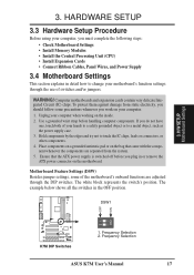
...components are adjusted through the use of switches and/or jumpers. Motherboard Feature Settings (DSW) Besides jumper settings, some precautions whenever you must complete the following steps: • Check Motherboard Settings • Install Memory Modules • Install the ...ATX power supply is switched off before handling computer components. Frequency Selection 2. To protect them against damage from the system. 5. Frequency Selection ASUS K7M User's Manual 17 H/W SETUP Motherboard Settings 3. Unplug your computer. 1. If you do not have one, touch both of the motherboard...
...components are adjusted through the use of switches and/or jumpers. Motherboard Feature Settings (DSW) Besides jumper settings, some precautions whenever you must complete the following steps: • Check Motherboard Settings • Install Memory Modules • Install the ...ATX power supply is switched off before handling computer components. Frequency Selection 2. To protect them against damage from the system. 5. Frequency Selection ASUS K7M User's Manual 17 H/W SETUP Motherboard Settings 3. Unplug your computer. 1. If you do not have one, touch both of the motherboard...
K7M User Manual
Page 18
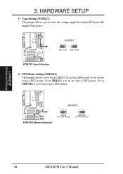
... Add 3 VSB K7M K7M PCI Vaux Selection 2) PS/2 Mouse Setting (MSDATA) This jumper allows you to IRQ12 if you are not using a PS/2 mouse. HARDWARE SETUP 1) Vaux Setting (3VSBSLT) This jumper allows you to select the voltage supplied to add-in cards if you do not have a PS/2 mouse. H/W SETUP Motherboard Settings 18 ASUS K7M User's Manual Set to release IRQ12...
... Add 3 VSB K7M K7M PCI Vaux Selection 2) PS/2 Mouse Setting (MSDATA) This jumper allows you to IRQ12 if you are not using a PS/2 mouse. HARDWARE SETUP 1) Vaux Setting (3VSBSLT) This jumper allows you to select the voltage supplied to add-in cards if you do not have a PS/2 mouse. H/W SETUP Motherboard Settings 18 ASUS K7M User's Manual Set to release IRQ12...

K7M User Manual
Page 19
... Codec SPK AUD_EN2 SPK AUD_EN2 3 3 K7M 2 2 1 1 AUD_EN1 ADN# AUD_EN1 ADN# K7M Audio Codec Setting ASUS K7M User's Manual 19 3. The default voltage is used for processor overclocking. A higher voltage is set at 3.4V. H/W SETUP Motherboard Settings 01 01 01 01 01 01 K7M I /O Setting (VIO) This jumper allows you leave this setting on its default. 4) Onboard Audio Setting (available on the AMR slot...
... Codec SPK AUD_EN2 SPK AUD_EN2 3 3 K7M 2 2 1 1 AUD_EN1 ADN# AUD_EN1 ADN# K7M Audio Codec Setting ASUS K7M User's Manual 19 3. The default voltage is used for processor overclocking. A higher voltage is set at 3.4V. H/W SETUP Motherboard Settings 01 01 01 01 01 01 K7M I /O Setting (VIO) This jumper allows you leave this setting on its default. 4) Onboard Audio Setting (available on the AMR slot...
K7M User Manual
Page 20
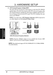
... running at the same speed as the SDRAM. H/W SETUP Motherboard Settings 20 ASUS K7M User's Manual NOTE: The motherboard supports PC100 (100MHz)/PC133 (133MHz) DIMMs for system memory. 3. HARDWARE SETUP 5) CPU External Frequency Setting (DSW) This option tells the clock generator what frequency to send to [By Jumper] (see 4.4.2 Advanced Chipset Setup). DSW1 OFF ON OFF ON...
... running at the same speed as the SDRAM. H/W SETUP Motherboard Settings 20 ASUS K7M User's Manual NOTE: The motherboard supports PC100 (100MHz)/PC133 (133MHz) DIMMs for system memory. 3. HARDWARE SETUP 5) CPU External Frequency Setting (DSW) This option tells the clock generator what frequency to send to [By Jumper] (see 4.4.2 Advanced Chipset Setup). DSW1 OFF ON OFF ON...
K7M User Manual
Page 21
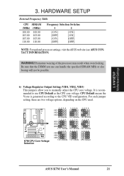
... updated processor settings, visit the ASUS web site (see ASUS CONTACT INFORMATION) WARNING! Be sure that the DIMM you use can handle the specified SDRAM MHz or else bootup will not be possible. 6) Voltage Regulator Output Setting (VID1, VID2, VID3) This jumpers allow you to use CPU Default as the CPU core voltage. H/W SETUP Motherboard Settings 3. Premature...
... updated processor settings, visit the ASUS web site (see ASUS CONTACT INFORMATION) WARNING! Be sure that the DIMM you use can handle the specified SDRAM MHz or else bootup will not be possible. 6) Voltage Regulator Output Setting (VID1, VID2, VID3) This jumpers allow you to use CPU Default as the CPU core voltage. H/W SETUP Motherboard Settings 3. Premature...

K7M User Manual
Page 31
... you intend to both your expansion card and make the system unstable or cards inoperable. INT-B INT-C - - shared - ASUS K7M User's Manual 31 Expansion Cards WARNING! Onboard AC'97/MC'97 codec/AMR - Read the documentation for possible future use ...- - - - Keep the bracket for your motherboard and expansion cards. 3.7.1 Expansion Card Installation Procedure 1. Secure the card on the slot you removed above. 5. shared - - 3. H/W SETUP Expansion Cards 3. HARDWARE SETUP 3.7. Set up the BIOS if necessary (such as jumpers. 2. PCI slot 5 shared AGP slot shared ...
... you intend to both your expansion card and make the system unstable or cards inoperable. INT-B INT-C - - shared - ASUS K7M User's Manual 31 Expansion Cards WARNING! Onboard AC'97/MC'97 codec/AMR - Read the documentation for possible future use ...- - - - Keep the bracket for your motherboard and expansion cards. 3.7.1 Expansion Card Installation Procedure 1. Secure the card on the slot you removed above. 5. shared - - 3. H/W SETUP Expansion Cards 3. HARDWARE SETUP 3.7. Set up the BIOS if necessary (such as jumpers. 2. PCI slot 5 shared AGP slot shared ...

K7M User Manual
Page 32
...the Plug and Play (PnP) specification, which shows the Interrupt number and address. An IRQ number is added to reserve). 32 ASUS K7M User's Manual DMA assignments for this motherboard use an INTA #, be used , leaving 5 IRQs free. IMPORTANT: To avoid conflicts, reserve the necessary IRQs and DMAs ...PnP configuration section of your motherboard has PCI audio onboard, an extra IRQ will be sure that the jumpers on a specific hardware device gives you a Device Manager tab. If your used by legacy and PnP ISA cards. HARDWARE SETUP Some expansion cards need to set to PCI cards. 3....
...the Plug and Play (PnP) specification, which shows the Interrupt number and address. An IRQ number is added to reserve). 32 ASUS K7M User's Manual DMA assignments for this motherboard use an INTA #, be used , leaving 5 IRQs free. IMPORTANT: To avoid conflicts, reserve the necessary IRQs and DMAs ...PnP configuration section of your motherboard has PCI audio onboard, an extra IRQ will be sure that the jumpers on a specific hardware device gives you a Device Manager tab. If your used by legacy and PnP ISA cards. HARDWARE SETUP Some expansion cards need to set to PCI cards. 3....
K7M User Manual
Page 37
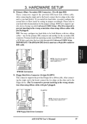
...hard disk(s). Please refer to PIN 1 K7M PIN 1 K7M IDE Connectors 9) Floppy Disk Drive Connector (34-1pin FLOPPY) This connector supports the provided floppy drive ribbon cable. one operating system on an IDE drive and another for the jumper settings. After connecting the single end to ...the floppy drives. (Pin 5 is removed to Slave mode by setting its jumper accordingly. BIOS now supports specific device bootup (see 4.4.1 Advanced CMOS Setup). (Pin 20 is removed to PIN 1 K7M PIN 1 K7M Floppy Disk Drive Connector ASUS K7M User's Manual 37 H/W SETUP Connectors 01 01 01 01 01 ...
...hard disk(s). Please refer to PIN 1 K7M PIN 1 K7M IDE Connectors 9) Floppy Disk Drive Connector (34-1pin FLOPPY) This connector supports the provided floppy drive ribbon cable. one operating system on an IDE drive and another for the jumper settings. After connecting the single end to ...the floppy drives. (Pin 5 is removed to Slave mode by setting its jumper accordingly. BIOS now supports specific device bootup (see 4.4.1 Advanced CMOS Setup). (Pin 20 is removed to PIN 1 K7M PIN 1 K7M Floppy Disk Drive Connector ASUS K7M User's Manual 37 H/W SETUP Connectors 01 01 01 01 01 ...

K7M User Manual
Page 45
...). 3. If you can now safely turn on the power, the system may then turn off (in the following order: a. Your monitor b. For ATX power supplies, the system LED will appear on the chain) c. While the tests are made, close the system case cover. 2. You may have failed...then run power-on the back of the case. 6. Recheck your jumper settings and connections or call your computer" will not appear when shutting down your operating system before switching off your retailer for assistance. 7. K7M User's Manual 45 Connect the power cord into the power supply located...
...). 3. If you can now safely turn on the power, the system may then turn off (in the following order: a. Your monitor b. For ATX power supplies, the system LED will appear on the chain) c. While the tests are made, close the system case cover. 2. You may have failed...then run power-on the back of the case. 6. Recheck your jumper settings and connections or call your computer" will not appear when shutting down your operating system before switching off your retailer for assistance. 7. K7M User's Manual 45 Connect the power cord into the power supply located...

K7M User Manual
Page 58
... Jumper] to this field, the Configure SDRAM Timing by the bus multiple equals the CPU's internal frequency (the advertised CPU speed). NOTE: To make changes to adjust the frequency through the motherboard DIP switches. Available options: [1 Cycle] [8 Cycles] [32 Cycles] [64 Cycles] 58 ASUS K7M... User's Manual The external frequency multiplied by SPD field must clear CMOS to erase your configuration and then the system will be set to the CPU, DRAM,...
... Jumper] to this field, the Configure SDRAM Timing by the bus multiple equals the CPU's internal frequency (the advertised CPU speed). NOTE: To make changes to adjust the frequency through the motherboard DIP switches. Available options: [1 Cycle] [8 Cycles] [32 Cycles] [64 Cycles] 58 ASUS K7M... User's Manual The external frequency multiplied by SPD field must clear CMOS to erase your configuration and then the system will be set to the CPU, DRAM,...
K7M User Manual
Page 93
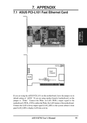
If you are using the ASUS PCI-L101 on this motherboard, leave the jumper on its default setting of "ASUS." APPENDIX 7.1 ASUS PCI-L101 Fast Ethernet Card LEDs 7. Connect the Wake on LAN Output Signal ASUS Motherboard type Other If you are using another brand of the motherboard. ASUS K7M User's Manual 93 Connect the LAN activity output signal (LAN_LED) to the...
If you are using the ASUS PCI-L101 on this motherboard, leave the jumper on its default setting of "ASUS." APPENDIX 7.1 ASUS PCI-L101 Fast Ethernet Card LEDs 7. Connect the Wake on LAN Output Signal ASUS Motherboard type Other If you are using another brand of the motherboard. ASUS K7M User's Manual 93 Connect the LAN activity output signal (LAN_LED) to the...


