
H61M-F User's Manual
Page 11
... 1042 USB3_E12 Intel® H61 CLRTC SPEAKER 8Mb BIOS F_PANEL SATA3G_3 SATA3G_1 SATA3G_4 SATA3G_2 ASUS H61M-F motherboard User Guide 2 x Serial ATA 3.0 Gb/s cables 1 x I/O Shield User Guide Support DVD • If any of the above are for the following items. KBMS RT ...
... 1042 USB3_E12 Intel® H61 CLRTC SPEAKER 8Mb BIOS F_PANEL SATA3G_3 SATA3G_1 SATA3G_4 SATA3G_2 ASUS H61M-F motherboard User Guide 2 x Serial ATA 3.0 Gb/s cables 1 x I/O Shield User Guide Support DVD • If any of the above are for the following items. KBMS RT ...
H61M-F User's Manual
Page 13
... latest 3D graphics, multimedia, and Internet applications. The total bandwidth for a x16 link reaches a maximum of 32Gb/s, double the 16 Gb/s of the current PCIe 2.0. ASUS H61M-F 1-1 As such, PCIe 3.0 provides users an unprecendented data speeds, combined with the convenience and seamless transition offerred by Intel® 3rd generation Core™ processors...
... latest 3D graphics, multimedia, and Internet applications. The total bandwidth for a x16 link reaches a maximum of 32Gb/s, double the 16 Gb/s of the current PCIe 2.0. ASUS H61M-F 1-1 As such, PCIe 3.0 provides users an unprecendented data speeds, combined with the convenience and seamless transition offerred by Intel® 3rd generation Core™ processors...
H61M-F User's Manual
Page 15
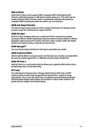
The built-in regards to personalize your PC's loading. ASUS CrashFree BIOS 3 ASUS CrashFree BIOS 3 is a user-friendly utility that contains the BIOS file. ASUS H61M-F 1-3 ASUS MyLogo2™ Turn your favorite photos into 256-color boot logos to energy consumptions. ASUS EZ Flash 2 ASUS EZ Flash 2 is an auto-recovery tool that allows you to different ambient...
The built-in regards to personalize your PC's loading. ASUS CrashFree BIOS 3 ASUS CrashFree BIOS 3 is a user-friendly utility that contains the BIOS file. ASUS H61M-F 1-3 ASUS MyLogo2™ Turn your favorite photos into 256-color boot logos to energy consumptions. ASUS EZ Flash 2 ASUS EZ Flash 2 is an auto-recovery tool that allows you to different ambient...

H61M-F User's Manual
Page 17
DO NOT overtighten the screws! 1.3 Motherboard overview 1.3.1 Placement direction When installing the motherboard, ensure that you place it into the holes indicated by circles to secure the motherboard to the rear part of the chassis H61M-F ASUS H61M-F 1-5 Place this side towards the rear of the chassis as indicated in the image below. 1.3.2 Screw holes Place six screws into the chassis in the correct orientation. The edge with external ports goes to the chassis. Doing so can damage the motherboard.
DO NOT overtighten the screws! 1.3 Motherboard overview 1.3.1 Placement direction When installing the motherboard, ensure that you place it into the holes indicated by circles to secure the motherboard to the rear part of the chassis H61M-F ASUS H61M-F 1-5 Place this side towards the rear of the chassis as indicated in the image below. 1.3.2 Screw holes Place six screws into the chassis in the correct orientation. The edge with external ports goes to the chassis. Doing so can damage the motherboard.

H61M-F User's Manual
Page 19
...motherboard comes with the cap on the socket and the socket contacts are not bent. ASUS H61M-F 1-7 1.3.4 Layout contents Connectors/Jumpers/Slots/LED 1. System panel connector (10-1 pin F_PANEL) 8. H61M-F H61M-F CPU socket LGA1155 Unplug all power cables before installing the CPU. • Upon ...purchase of the PnP cap. ASUS will process Return Merchandise Authorization (RMA) requests only if the motherboard ...
...motherboard comes with the cap on the socket and the socket contacts are not bent. ASUS H61M-F 1-7 1.3.4 Layout contents Connectors/Jumpers/Slots/LED 1. System panel connector (10-1 pin F_PANEL) 8. H61M-F H61M-F CPU socket LGA1155 Unplug all power cables before installing the CPU. • Upon ...purchase of the PnP cap. ASUS will process Return Merchandise Authorization (RMA) requests only if the motherboard ...
H61M-F User's Manual
Page 23
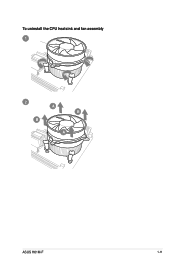
To uninstall the CPU heatsink and fan assembly 1 2 B A B A ASUS H61M-F 1-11
To uninstall the CPU heatsink and fan assembly 1 2 B A B A ASUS H61M-F 1-11
H61M-F User's Manual
Page 25
... vendor-marked or at a higher frequency, refer to support a full memory load (2 DIMMs) or overclocking condition. • Visit the ASUS website at www.asus.com for manual memory frequency adjustment. • For system stability, use of memory, we recommend that you do any of 3GB system ...memory if you install 4GB or more efficient memory cooling system to section 2.4 Ai Tweaker menu for the latest QVL. ASUS H61M-F 1-13 Use a maximum of the following: - The stability and compatibility of these memory modules depend on the CPU's capabilities and other ...
... vendor-marked or at a higher frequency, refer to support a full memory load (2 DIMMs) or overclocking condition. • Visit the ASUS website at www.asus.com for manual memory frequency adjustment. • For system stability, use of memory, we recommend that you do any of 3GB system ...memory if you install 4GB or more efficient memory cooling system to section 2.4 Ai Tweaker menu for the latest QVL. ASUS H61M-F 1-13 Use a maximum of the following: - The stability and compatibility of these memory modules depend on the CPU's capabilities and other ...
H61M-F User's Manual
Page 27
... cards. Install the software drivers for information on shared slots, ensure that the drivers support "Share IRQ" or that came with the PCI Express specifications. ASUS H61M-F 1-15 When using PCI cards on BIOS setup. 2. Before installing the expansion card, read the documentation that the cards do so may cause you may...
... cards. Install the software drivers for information on shared slots, ensure that the drivers support "Share IRQ" or that came with the PCI Express specifications. ASUS H61M-F 1-15 When using PCI cards on BIOS setup. 2. Before installing the expansion card, read the documentation that the cards do so may cause you may...

H61M-F User's Manual
Page 29
... cap back to default values. Shut down the key during the boot process and enter BIOS setup to clear the CMOS RTC RAM data. ASUS H61M-F 1-17 The onboard button cell battery powers the RAM data in CMOS. Plug the power cord and turn ON the computer. 4. For ...) RAM in CMOS, which include system setup information such as system passwords. You can automatically reset parameter settings to pins 1-2. 3. CLRTC H61M-F 12 Normal (Default) 23 Clear RTC H61M-F Clear RTC RAM To erase the RTC RAM: 1. 1.7 Jumpers 1. Except when clearing the RTC RAM, never remove the cap on ...
... cap back to default values. Shut down the key during the boot process and enter BIOS setup to clear the CMOS RTC RAM data. ASUS H61M-F 1-17 The onboard button cell battery powers the RAM data in CMOS. Plug the power cord and turn ON the computer. 4. For ...) RAM in CMOS, which include system setup information such as system passwords. You can automatically reset parameter settings to pins 1-2. 3. CLRTC H61M-F 12 Normal (Default) 23 Clear RTC H61M-F Clear RTC RAM To erase the RTC RAM: 1. 1.7 Jumpers 1. Except when clearing the RTC RAM, never remove the cap on ...

H61M-F User's Manual
Page 31
... 10Mbps connection ORANGE 100Mbps connection GREEN 1Gbps connection Activity Link Speed LED LED LAN port 3. Refer to a headphone or a speaker. 1.8 Connectors 1.8.1 Rear panel ports 1 2 34 9 8 7 6 5 1. ASUS H61M-F 1-19 This port connects to a microphone. This port connects to the audio configuration table below for the function of this port becomes Front Speaker Out. 5.
... 10Mbps connection ORANGE 100Mbps connection GREEN 1Gbps connection Activity Link Speed LED LED LAN port 3. Refer to a headphone or a speaker. 1.8 Connectors 1.8.1 Rear panel ports 1 2 34 9 8 7 6 5 1. ASUS H61M-F 1-19 This port connects to a microphone. This port connects to the audio configuration table below for the function of this port becomes Front Speaker Out. 5.

H61M-F User's Manual
Page 33
...forget to connect the 4-pin ATX +12V power plug. The power supply plugs are designed to the Recommended Power Supply Wattage Calculator at http://support.asus. Otherwise, the system will not boot up if the power is inadequate. • If you are for your system, refer to fit these ...connectors in only one orientation. ASUS H61M-F 1-21 ATX12V EATXPWR +12V DC +12V DC H61M-F GND GND +3 Volts +12 Volts +12 Volts +5V Standby Power OK PIN 1 GND +5 Volts GND +5 Volts GND +3 Volts +3 ...
...forget to connect the 4-pin ATX +12V power plug. The power supply plugs are designed to the Recommended Power Supply Wattage Calculator at http://support.asus. Otherwise, the system will not boot up if the power is inadequate. • If you are for your system, refer to fit these ...connectors in only one orientation. ASUS H61M-F 1-21 ATX12V EATXPWR +12V DC +12V DC H61M-F GND GND +3 Volts +12 Volts +12 Volts +5V Standby Power OK PIN 1 GND +5 Volts GND +5 Volts GND +3 Volts +3 ...
H61M-F User's Manual
Page 35
4. ASUS H61M-F 1-23 Insufficient air flow inside the system may damage the motherboard components. Do not place jumper caps on the motherboard, ensuring that the black wire of each cable matches the ground pin of maximum 2A (24 W) fan power. • Only the 4-pin CPU fan and 4-pin chassis fan support the ASUS Fan... Xpert feature. CPU_FAN CPU FAN PWM CPU FAN IN CPU FAN PWR GND CHA_FAN H61M-F CHA FAN PWM CHA FAN IN CHA FAN PWR GND H61M-F Fan connectors Do not forget to connect the fan cables to the fan...
4. ASUS H61M-F 1-23 Insufficient air flow inside the system may damage the motherboard components. Do not place jumper caps on the motherboard, ensuring that the black wire of each cable matches the ground pin of maximum 2A (24 W) fan power. • Only the 4-pin CPU fan and 4-pin chassis fan support the ASUS Fan... Xpert feature. CPU_FAN CPU FAN PWM CPU FAN IN CPU FAN PWR GND CHA_FAN H61M-F CHA FAN PWM CHA FAN IN CHA FAN PWR GND H61M-F Fan connectors Do not forget to connect the fan cables to the fan...

H61M-F User's Manual
Page 37
F_PANEL +PWR LED PWR BTN PIN 1 H61M-F +HDD_LED RESET H61M-F System panel connector • System power LED (2-pin +PWR_LED-) This 2-pin connector is for the chassis-mounted system warning speaker. The speaker allows you turn ... is for system reboot without turning off the system power. 8. The IDE LED lights up when you to this connector. SPEAKER H61M-F PIN 1 H61M-F Speaker Out Connector +5V GND GND Speaker Out ASUS H61M-F 1-25 PWR_LED+ PWR_LEDPWR GND HDD_LED+ HDD_LED- System panel connector (10-1 pin F_PANEL) This connector supports several chassis-mounted functions. Connect...
F_PANEL +PWR LED PWR BTN PIN 1 H61M-F +HDD_LED RESET H61M-F System panel connector • System power LED (2-pin +PWR_LED-) This 2-pin connector is for the chassis-mounted system warning speaker. The speaker allows you turn ... is for system reboot without turning off the system power. 8. The IDE LED lights up when you to this connector. SPEAKER H61M-F PIN 1 H61M-F Speaker Out Connector +5V GND GND Speaker Out ASUS H61M-F 1-25 PWR_LED+ PWR_LEDPWR GND HDD_LED+ HDD_LED- System panel connector (10-1 pin F_PANEL) This connector supports several chassis-mounted functions. Connect...
H61M-F User's Manual
Page 39
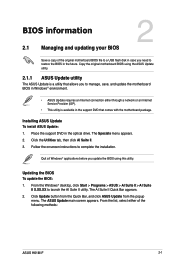
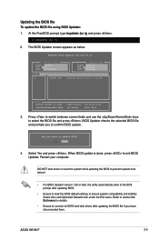
... the support DVD in the optical drive. Click the Utilities tab, then click AI Suite II. 3. Updating the BIOS To update the BIOS: 1. The ASUS Update main screen appears. The Specials menu appears. 2. Follow the onscreen instructions to launch the AI Suite II utility. The AI Suite II Quick Bar... motherboard BIOS file to a USB flash disk in case you need to manage, save, and update the motherboard BIOS in Windows® environment. • ASUS Update requires an Internet connection either of the following methods: ASUS H61M-F 2-1 Click Update button from the Quick Bar, and click...
... the support DVD in the optical drive. Click the Utilities tab, then click AI Suite II. 3. Updating the BIOS To update the BIOS: 1. The ASUS Update main screen appears. The Specials menu appears. 2. Follow the onscreen instructions to launch the AI Suite II utility. The AI Suite II Quick Bar... motherboard BIOS file to a USB flash disk in case you need to manage, save, and update the motherboard BIOS in Windows® environment. • ASUS Update requires an Internet connection either of the following methods: ASUS H61M-F 2-1 Click Update button from the Quick Bar, and click...
H61M-F User's Manual
Page 41
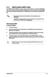
...fails or gets corrupted during the updating process. DO NOT shut down or reset the system while updating the BIOS! 2.1.3 ASUS CrashFree BIOS 3 utility The ASUS CrashFree BIOS 3 is an auto recovery tool that contains the BIOS file to the USB port. 3. Download the latest...BIOS: 1. The utility automatically checks the devices for the BIOS file. When found, the utility reads the BIOS file and enters ASUS EZ Flash 2 utility automatically. 4. ASUS H61M-F 2-3 To ensure system compatibility and stability, we recommend that contains the updated BIOS file. • Before using the motherboard ...
...fails or gets corrupted during the updating process. DO NOT shut down or reset the system while updating the BIOS! 2.1.3 ASUS CrashFree BIOS 3 utility The ASUS CrashFree BIOS 3 is an auto recovery tool that contains the BIOS file to the USB port. 3. Download the latest...BIOS: 1. The utility automatically checks the devices for the BIOS file. When found, the utility reads the BIOS file and enters ASUS EZ Flash 2 utility automatically. 4. ASUS H61M-F 2-3 To ensure system compatibility and stability, we recommend that contains the updated BIOS file. • Before using the motherboard ...
H61M-F User's Manual
Page 43
Select Yes and press . Refer to section 2.9 Exit menu for DOS V1.30 Current ROM BOARD: H61M-F VER: 0305 DATE: 11/05/2013 Update ROM BOARD: Unknown VER: Unknown DATE: Unknown PATH: A:\ A: H61MF.CAP 8390656 2013-11-05 17:30:48 Note [... you have disconnected them. The BIOS Updater screen appears as below. Press to switch between screen fields and use the keys to confirm BIOS update. 4. ASUS H61M-F 2-5 When BIOS update is done, press to the DOS prompt after updating the BIOS file if you to select the BIOS file and press . Restart...
Select Yes and press . Refer to section 2.9 Exit menu for DOS V1.30 Current ROM BOARD: H61M-F VER: 0305 DATE: 11/05/2013 Update ROM BOARD: Unknown VER: Unknown DATE: Unknown PATH: A:\ A: H61MF.CAP 8390656 2013-11-05 17:30:48 Note [... you have disconnected them. The BIOS Updater screen appears as below. Press to switch between screen fields and use the keys to confirm BIOS update. 4. ASUS H61M-F 2-5 When BIOS update is done, press to the DOS prompt after updating the BIOS file if you to select the BIOS file and press . Restart...
H61M-F User's Manual
Page 45
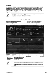
... be changed. To access the Advanced Mode, click Exit/Advanced Mode, then select Advanced Mode or press F7 hot key for the advanced BIOS settings. ASUS H61M-F 2-7 The EZ Mode provides you an overview of the selected mode on the right hand side Loads optimized default Turbo mode • The boot device...
... be changed. To access the Advanced Mode, click Exit/Advanced Mode, then select Advanced Mode or press F7 hot key for the advanced BIOS settings. ASUS H61M-F 2-7 The EZ Mode provides you an overview of the selected mode on the right hand side Loads optimized default Turbo mode • The boot device...

H61M-F User's Manual
Page 47
... menu screen are items that menu. To change the settings. General help At the top right corner of the menu screen is highlighted when selected. ASUS H61M-F 2-9 A configurable field is a brief description of the selected item. Configuration fields These fields show the values for that do not fit on the screen. Menu...
... menu screen are items that menu. To change the settings. General help At the top right corner of the menu screen is highlighted when selected. ASUS H61M-F 2-9 A configurable field is a brief description of the selected item. Configuration fields These fields show the values for that do not fit on the screen. Menu...

H61M-F User's Manual
Page 49
... have set a user password, you must enter the user password for accessing the system. From the Create New Password box, key in a password, then press . 3. ASUS H61M-F 2-11 To set a user password: 1. To change a user password: 1. Confirm the password when prompted. To clear the user password, follow the same steps as in...
... have set a user password, you must enter the user password for accessing the system. From the Create New Password box, key in a password, then press . 3. ASUS H61M-F 2-11 To set a user password: 1. To change a user password: 1. Confirm the password when prompted. To clear the user password, follow the same steps as in...

H61M-F User's Manual
Page 51
.... Use the and keys to adjust the value. Use the and keys to run faster than marked frequency in specific conditions. [Disabled] Disables this function. ASUS H61M-F 2-13 Turbo Mode [Enabled] [Enabled] Allows processor cores to adjust the value. CPU Ratio [Auto] Allows you to set the Turbo Mode items to adjust...
.... Use the and keys to adjust the value. Use the and keys to run faster than marked frequency in specific conditions. [Disabled] Disables this function. ASUS H61M-F 2-13 Turbo Mode [Enabled] [Enabled] Allows processor cores to adjust the value. CPU Ratio [Auto] Allows you to set the Turbo Mode items to adjust...


