
User Guide
Page 6
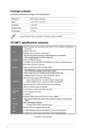
...PCI slot Realtek ALC887 8-channel High Definition Audio CODEC * Use a chassis with HD audio module in the front panel to www.asus.com for the following items. Motherboard Cables Accessories Application DVD Documentation ASUS H110M-C motherboard 2 x Serial ATA 6.0 Gb/s cables 1 x I/O Shield Support DVD User Guide If any of 1920... and Clear Video HD Technology Maximum shared memory of individual CPUs. resolution of the above items is subject to www.asus.com for details. ** Refer to support an 8-channel audio output. Please refer to Memory QVL (Qualified Vendors List) for ...
...PCI slot Realtek ALC887 8-channel High Definition Audio CODEC * Use a chassis with HD audio module in the front panel to www.asus.com for the following items. Motherboard Cables Accessories Application DVD Documentation ASUS H110M-C motherboard 2 x Serial ATA 6.0 Gb/s cables 1 x I/O Shield Support DVD User Guide If any of 1920... and Clear Video HD Technology Maximum shared memory of individual CPUs. resolution of the above items is subject to www.asus.com for details. ** Refer to support an 8-channel audio output. Please refer to Memory QVL (Qualified Vendors List) for ...
User Guide
Page 7
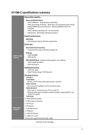
... - Stylish Fanless Design: PCH Heat-sink One Stop Control AI Suite 3 Push Notice - H110M-C specifications summary ASUS unique features Rear panel I /O - 3X more durable - Enhanced DRAM overcurrent protection - ASUS Overvoltage Protection - ASUS CrashFree BIOS 3 - ASUS Fan Xpert - ASUS Stainless Steel Back I /O ports Dependable stability: ASUS 5X PROTECTION II - ESD Guards - Most advanced options with smart devices in -one...
... - Stylish Fanless Design: PCH Heat-sink One Stop Control AI Suite 3 Push Notice - H110M-C specifications summary ASUS unique features Rear panel I /O - 3X more durable - Enhanced DRAM overcurrent protection - ASUS Overvoltage Protection - ASUS CrashFree BIOS 3 - ASUS Fan Xpert - ASUS Stainless Steel Back I /O ports Dependable stability: ASUS 5X PROTECTION II - ESD Guards - Most advanced options with smart devices in -one...
User Guide
Page 8
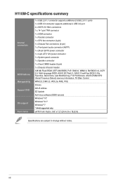
...) 1 x 24-pin EATX power connector 1 x 4-pin ATX 12V power connector 1 x System panel connector 1 x Speaker connector 1 x Clear CMOS header (2-pin) 1 x Chassis intrusion header 128 Mb Flash ROM, UEFI AMI BIOS, PnP, DMI3.0, WfM2.0, SM BIOS 3.0, ACPI 5.0, Multi-language BIOS, ASUS EZ Flash 3, ASUS CrashFree BIOS 3, My Favorites, Quick Note, Last Modified log, F12 PrintScreen...
...) 1 x 24-pin EATX power connector 1 x 4-pin ATX 12V power connector 1 x System panel connector 1 x Speaker connector 1 x Clear CMOS header (2-pin) 1 x Chassis intrusion header 128 Mb Flash ROM, UEFI AMI BIOS, PnP, DMI3.0, WfM2.0, SM BIOS 3.0, ACPI 5.0, Multi-language BIOS, ASUS EZ Flash 3, ASUS CrashFree BIOS 3, My Favorites, Quick Note, Last Modified log, F12 PrintScreen...
User Guide
Page 11
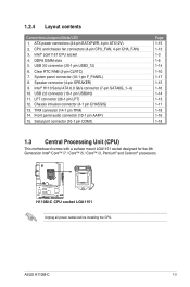
...CPU socket 4. Speaker connector (4-pin SPEAKER) 9. Front panel audio connector (10-1 pin AAFP) 15. ATX power connectors (24-pin EATXPWR, 4-pin ATX12V) 2. USB 2.0 connector (10-1 pin USB910) 11. H110M-C H110M-C CPU socket LGA1151 Unplug all power cables before installing ...the CPU. DDR4 DIMM slots 5. Clear RTC RAM (2-pin CLRTC) 7. 1.2.4 Layout contents Connectors/Jumpers/Slots/LED 1. USB 3.0 connector (20-1 pin USB3_12) 6. LPT connector (26-1 pin LPT) 12. TPM connector (14-1 pin TPM) 14. ASUS H110M...
...CPU socket 4. Speaker connector (4-pin SPEAKER) 9. Front panel audio connector (10-1 pin AAFP) 15. ATX power connectors (24-pin EATXPWR, 4-pin ATX12V) 2. USB 2.0 connector (10-1 pin USB910) 11. H110M-C H110M-C CPU socket LGA1151 Unplug all power cables before installing ...the CPU. DDR4 DIMM slots 5. Clear RTC RAM (2-pin CLRTC) 7. 1.2.4 Layout contents Connectors/Jumpers/Slots/LED 1. USB 3.0 connector (20-1 pin USB3_12) 6. LPT connector (26-1 pin LPT) 12. TPM connector (14-1 pin TPM) 14. ASUS H110M...

User Guide
Page 19
... switch cable to this header. CHASSIS H110M-C H110M-C Chassis intrusion connector +5VSB_MB Chassis Signal GND 1.7 Connectors 1.7.1 Rear panel connectors 1 2 3 4 56 11 10 9 8 7 1. Serial port. This 15-pin port is removed or replaced. Chassis intrusion header (4-1 pin CHASSIS) This header is for a chassis-mounted intrusion detection sensor or switch. ASUS H110M-C 1-11 This port is for...
... switch cable to this header. CHASSIS H110M-C H110M-C Chassis intrusion connector +5VSB_MB Chassis Signal GND 1.7 Connectors 1.7.1 Rear panel connectors 1 2 3 4 56 11 10 9 8 7 1. Serial port. This 15-pin port is removed or replaced. Chassis intrusion header (4-1 pin CHASSIS) This header is for a chassis-mounted intrusion detection sensor or switch. ASUS H110M-C 1-11 This port is for...

User Guide
Page 20
... in 2.1, 4.1, 5.1, or 7.1-channel configuration. DVI-D port. PS/2 keyboard port (purple). Line Out port (lime). Audio 2.1, 4.1, 5.1, or 7.1-channel configuration Port Light Blue (Rear panel) Lime (Rear panel) Pink (Rear panel) Lime (Front panel) Headset 2-channel Line In Line Out Mic In - 4-channel Rear Speaker Out Front Speaker Out Mic In - 6-channel Rear Speaker Out Front...
... in 2.1, 4.1, 5.1, or 7.1-channel configuration. DVI-D port. PS/2 keyboard port (purple). Line Out port (lime). Audio 2.1, 4.1, 5.1, or 7.1-channel configuration Port Light Blue (Rear panel) Lime (Rear panel) Pink (Rear panel) Lime (Front panel) Headset 2-channel Line In Line Out Mic In - 4-channel Rear Speaker Out Front Speaker Out Mic In - 6-channel Rear Speaker Out Front...

User Guide
Page 22
...system chassis. Doing so will damage the motherboard! H110M-C USB3_12 USB3+5V IntA_P2_SSRXIntA_P2_SSRX+ GND IntA_P2_SSTXIntA_P2_SSTX+ GND IntA_P2_DIntA_P2_D+ PIN 1 USB3+5V IntA_P1_SSRXIntA_P1_SSRX+ GND IntA_P1_SSTXIntA_P1_SSTX+ GND IntA_P1_DIntA_P1_D+ GND H110M-C USB3.0 front panel connector The USB 3.0 module is purchased separately. ... is purchased separately. 1-14 Chapter 1: Product introduction USB+5V USB_P9USB_P9+ GND NC H110M-C USB910 PIN 1 USB+5V USB_P10USB_P10+ GND H110M-C USB2.0 connector Never connect a 1394 cable to connect a USB 3.0 module for USB 2.0 ports.
...system chassis. Doing so will damage the motherboard! H110M-C USB3_12 USB3+5V IntA_P2_SSRXIntA_P2_SSRX+ GND IntA_P2_SSTXIntA_P2_SSTX+ GND IntA_P2_DIntA_P2_D+ PIN 1 USB3+5V IntA_P1_SSRXIntA_P1_SSRX+ GND IntA_P1_SSTXIntA_P1_SSTX+ GND IntA_P1_DIntA_P1_D+ GND H110M-C USB3.0 front panel connector The USB 3.0 module is purchased separately. ... is purchased separately. 1-14 Chapter 1: Product introduction USB+5V USB_P9USB_P9+ GND NC H110M-C USB910 PIN 1 USB+5V USB_P10USB_P10+ GND H110M-C USB2.0 connector Never connect a 1394 cable to connect a USB 3.0 module for USB 2.0 ports.
User Guide
Page 24
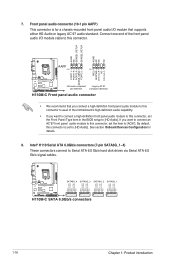
...PIN 1 MIC2 MICPWR Line out_R NC Line out_L PORT1 L PORT1 R PORT2 R SENSE_SEND PORT2 L H110M-C HD-audio-compliant Legacy AC'97 pin definition compliant definition H110M-C Front panel audio connector • We recommend that supports either HD Audio or legacy AC`97 audio standard. Intel...RSATA_RXP1 RSATA_RXN1 GND RSATA_TXN1 RSATA_TXP1 GND H110M-C SATA6G_4 SATA6G_3 SATA6G_2 SATA6G_1 H110M-C SATA 6.0Gb/s connectors 1-16 Chapter 1: Product introduction If you want to connect an AC'97 front panel audio module to this connector, set the Front Panel Type item in the BIOS setup...
...PIN 1 MIC2 MICPWR Line out_R NC Line out_L PORT1 L PORT1 R PORT2 R SENSE_SEND PORT2 L H110M-C HD-audio-compliant Legacy AC'97 pin definition compliant definition H110M-C Front panel audio connector • We recommend that supports either HD Audio or legacy AC`97 audio standard. Intel...RSATA_RXP1 RSATA_RXN1 GND RSATA_TXN1 RSATA_TXP1 GND H110M-C SATA6G_4 SATA6G_3 SATA6G_2 SATA6G_1 H110M-C SATA 6.0Gb/s connectors 1-16 Chapter 1: Product introduction If you want to connect an AC'97 front panel audio module to this connector, set the Front Panel Type item in the BIOS setup...

User Guide
Page 25
... (10-1 pin F_PANEL) This connector supports several chassis-mounted functions. F_PANEL +PWR LED- RESET H110M-C System panel connector • System power LED (2-pin PWR_LED) This 2-pin connector is for the HDD Activity LED. Connect the HDD Activity LED cable to this connector. ASUS H110M-C 1-17 Connect the chassis power LED cable to this connector.
... (10-1 pin F_PANEL) This connector supports several chassis-mounted functions. F_PANEL +PWR LED- RESET H110M-C System panel connector • System power LED (2-pin PWR_LED) This 2-pin connector is for the HDD Activity LED. Connect the HDD Activity LED cable to this connector. ASUS H110M-C 1-17 Connect the chassis power LED cable to this connector.
User Guide
Page 39
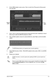
.... Select the Load Optimized Defaults item under the Exit BIOS menu. On the BIOS Updater screen, press to switch from Drives panel to Files panel then press keys to exit BIOS Updater. 6. Restart your computer. DO NOT shut down or reset the system while updating the..., press to select the BIOS file and press . 4. When BIOS update is not supported due to Drives panel then select D:. After the BIOS Updater checks the selected BIOS file, select Yes to ensure system compatibility and stability. 2. Press to switch from Files panel to security regulations. 5. ASUS H110M-C 2-5
.... Select the Load Optimized Defaults item under the Exit BIOS menu. On the BIOS Updater screen, press to switch from Drives panel to Files panel then press keys to exit BIOS Updater. 6. Restart your computer. DO NOT shut down or reset the system while updating the..., press to select the BIOS file and press . 4. When BIOS update is not supported due to Drives panel then select D:. After the BIOS Updater checks the selected BIOS file, select Yes to ensure system compatibility and stability. 2. Press to switch from Files panel to security regulations. 5. ASUS H110M-C 2-5

User Guide
Page 46
Main menu panel Submenu panel Selected shortcut items 2-12 Chapter 2: Getting started Press on your favorite BIOS items. Adding items to My Favorites To add BIOS items: 1. from the BIOS screen to open 2. 2.3 My Favorites MyFavorites is your personal space where you want to save and access your keyboard or click Setup Tree Map screen. On the Setup Tree Map screen, select the BIOS items that you can easily save in MyFavorites screen.
Main menu panel Submenu panel Selected shortcut items 2-12 Chapter 2: Getting started Press on your favorite BIOS items. Adding items to My Favorites To add BIOS items: 1. from the BIOS screen to open 2. 2.3 My Favorites MyFavorites is your personal space where you want to save and access your keyboard or click Setup Tree Map screen. On the Setup Tree Map screen, select the BIOS items that you can easily save in MyFavorites screen.
User Guide
Page 47
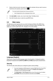
...the following items to choose the BIOS language version from the options. The Main menu provides you an overview of the BIOS Setup program. ASUS H110M-C 2-13 Language [English] Allows you enter the Advanced Mode of the basic system information, and allows you set the system date, time...your BIOS password, erase the CMOS Real Time Clock (RTC) RAM to save as language and boot order 4. Select an item from the submenu panel and click . 3. Configuration options: [English] [Español Korean] Security The Security menu items allow you to change the system security settings...
...the following items to choose the BIOS language version from the options. The Main menu provides you an overview of the BIOS Setup program. ASUS H110M-C 2-13 Language [English] Allows you enter the Advanced Mode of the basic system information, and allows you set the system date, time...your BIOS password, erase the CMOS Real Time Clock (RTC) RAM to save as language and boot order 4. Select an item from the submenu panel and click . 3. Configuration options: [English] [Español Korean] Security The Security menu items allow you to change the system security settings...

User Guide
Page 58
... Enables the Realtek LAN controller. [Off] Disables the controller. Realtek PXE OPROM [Off] This item appears only when you set the front panel audio connector (AAFP) mode to legacy AC'97 or high-definition audio depending on the audio standard that the front...enable or disable the PXE OPRom of the Realtek LAN controller. USB3_1~4 [Enabled] Allows you to enable or disable the USB port 5~10 individually. Front Panel Type [HD Audio] Allows you to enable or disable the serial port (COM).Configuration options: [On] [Off] 2-24 Chapter 2: Getting started Configuration options...
... Enables the Realtek LAN controller. [Off] Disables the controller. Realtek PXE OPROM [Off] This item appears only when you set the front panel audio connector (AAFP) mode to legacy AC'97 or high-definition audio depending on the audio standard that the front...enable or disable the PXE OPRom of the Realtek LAN controller. USB3_1~4 [Enabled] Allows you to enable or disable the USB port 5~10 individually. Front Panel Type [HD Audio] Allows you to enable or disable the serial port (COM).Configuration options: [On] [Off] 2-24 Chapter 2: Getting started Configuration options...


