F2A85-V User's Manual
Page 12
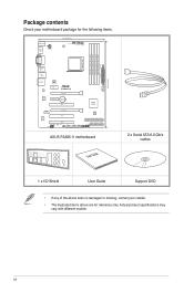
...DVI_VGA 30.5cm(12.0in) ESATA6G _USB3 _12 LAN _USB12 DRAM_LED MemOK! xii EATXPWR AUDIO Atheros 8161 Super I/O CHA_FAN1 PCIEX1_1 F2A85-V PCIEX16_1 PCIEX1_2 Lithium Cell CMOS Power PCI1 COM PCIEX16_2 Realtek ALC887 PCI2 SPDIF_OUT AAFP PCI3 SB_PWR CLRTC USB910 USB78 USB56 AMD...® A85X 64Mb BIOS SATA6G_4 SATA6G_5 SATA6G_6 SATA6G_7 SATA6G_1 SATA6G_2 SATA6G_3 PANEL USB3_34 ASUS F2A85-V motherboard User Guide 2 x Serial ATA 6.0 Gb/s cables 1 x I/O Shield User Guide Support DVD • If any of...
...DVI_VGA 30.5cm(12.0in) ESATA6G _USB3 _12 LAN _USB12 DRAM_LED MemOK! xii EATXPWR AUDIO Atheros 8161 Super I/O CHA_FAN1 PCIEX1_1 F2A85-V PCIEX16_1 PCIEX1_2 Lithium Cell CMOS Power PCI1 COM PCIEX16_2 Realtek ALC887 PCI2 SPDIF_OUT AAFP PCI3 SB_PWR CLRTC USB910 USB78 USB56 AMD...® A85X 64Mb BIOS SATA6G_4 SATA6G_5 SATA6G_6 SATA6G_7 SATA6G_1 SATA6G_2 SATA6G_3 PANEL USB3_34 ASUS F2A85-V motherboard User Guide 2 x Serial ATA 6.0 Gb/s cables 1 x I/O Shield User Guide Support DVD • If any of...
F2A85-V User's Manual
Page 13
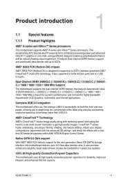
Product introduction 1 1.1 Special features 1.1.1 Product highlights AMD® A-series and Athlon™ Series processors This motherboard supports AMD® A-series and Athlon™ Series processors. ASUS F2A85-V 1-1 This revolutionary APU (Accelerated Processing Unit) combines processing power and advanced DirectX 11 graphics in one small, energy-efficient design to 6.0 Gb/s data transfer rates. ...
Product introduction 1 1.1 Special features 1.1.1 Product highlights AMD® A-series and Athlon™ Series processors This motherboard supports AMD® A-series and Athlon™ Series processors. ASUS F2A85-V 1-1 This revolutionary APU (Accelerated Processing Unit) combines processing power and advanced DirectX 11 graphics in one small, energy-efficient design to 6.0 Gb/s data transfer rates. ...
F2A85-V User's Manual
Page 15
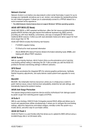
...the following new features: • F12 BIOS snapshot hotkey • F3 Shortcut for a more flexibility, convenience, and easy to -use . ASUS F2A85-V 1-3 Network iControl Network iControl is a user-friendly utility that allows you to update the BIOS without exiting or rebooting the OS. It offers... detecting faulty DIMMs, and helping with dual selectable modes and native support for hard drives larger than the traditional BIOS versions. ASUS EZ Flash 2 ASUS EZ Flash 2 is an intuitive one-step network control center that makes it easier for you to manage your bandwidth and allows...
...the following new features: • F12 BIOS snapshot hotkey • F3 Shortcut for a more flexibility, convenience, and easy to -use . ASUS F2A85-V 1-3 Network iControl Network iControl is a user-friendly utility that allows you to update the BIOS without exiting or rebooting the OS. It offers... detecting faulty DIMMs, and helping with dual selectable modes and native support for hard drives larger than the traditional BIOS versions. ASUS EZ Flash 2 ASUS EZ Flash 2 is an intuitive one-step network control center that makes it easier for you to manage your bandwidth and allows...
F2A85-V User's Manual
Page 17
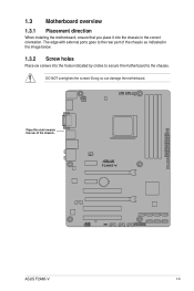
Place this side towards the rear of the chassis as indicated in the image below. 1.3.2 Screw holes Place six screws into the chassis in the correct orientation. The edge with external ports goes to the chassis. F2A85-V ASUS F2A85-V 1-5 DO NOT overtighten the screws! Doing so can damage the motherboard. 1.3 Motherboard overview 1.3.1 Placement direction When installing the motherboard, ensure that you place it into the holes indicated by circles to secure the motherboard to the rear part of the chassis.
Place this side towards the rear of the chassis as indicated in the image below. 1.3.2 Screw holes Place six screws into the chassis in the correct orientation. The edge with external ports goes to the chassis. F2A85-V ASUS F2A85-V 1-5 DO NOT overtighten the screws! Doing so can damage the motherboard. 1.3 Motherboard overview 1.3.1 Placement direction When installing the motherboard, ensure that you place it into the holes indicated by circles to secure the motherboard to the rear part of the chassis.
F2A85-V User's Manual
Page 19
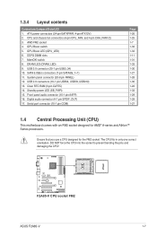
... 1-28 1-30 1-22 1-33 1-29 1-29 1-27 1.4 Central Processing Unit (CPU) This motherboard comes with an FM2 socket designed for the FM2 socket. F2A85-V F2A85-V CPU socket FM2 ASUS F2A85-V 1-7 ATX power connectors (24-pin EATXPWR, 4-pin ATX12V) 2. The CPU fits in only one correct orientation. DO NOT force the CPU into the socket...
... 1-28 1-30 1-22 1-33 1-29 1-29 1-27 1.4 Central Processing Unit (CPU) This motherboard comes with an FM2 socket designed for the FM2 socket. F2A85-V F2A85-V CPU socket FM2 ASUS F2A85-V 1-7 ATX power connectors (24-pin EATXPWR, 4-pin ATX12V) 2. The CPU fits in only one correct orientation. DO NOT force the CPU into the socket...
F2A85-V User's Manual
Page 21
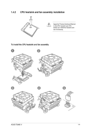
1.4.2 CPU heatsink and fan assembly installation Apply the Thermal Interface Material to the CPU heatsink and CPU before you install the heatsink and fan if necessary. To install the CPU heatsink and fan assembly 1 2 3 4 5 ASUS F2A85-V 1-9
1.4.2 CPU heatsink and fan assembly installation Apply the Thermal Interface Material to the CPU heatsink and CPU before you install the heatsink and fan if necessary. To install the CPU heatsink and fan assembly 1 2 3 4 5 ASUS F2A85-V 1-9
F2A85-V User's Manual
Page 23
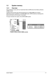
DDR3 modules are developed for better performance with four Double Data Rate 3 (DDR3) Dual Inline Memory Modules (DIMM) sockets. A DDR3 module has the same physical dimensions as a DDR2 DIMM but is notched differently to prevent installation on a DDR2 DIMM socket. The figure illustrates the location of the DDR3 DIMM sockets: DIMM_A1 DIMM_A2 DIMM_B1 DIMM_B2 Channel Sockets F2A85-V Channel A DIMM_A1 and DIMM_A2 Channel B DIMM_B1 and DIMM_B2 F2A85-V 240-pin DDR3 DIMM sockets ASUS F2A85-V 1-11 1.5 System memory 1.5.1 Overview This motherboard comes with less power consumption.
DDR3 modules are developed for better performance with four Double Data Rate 3 (DDR3) Dual Inline Memory Modules (DIMM) sockets. A DDR3 module has the same physical dimensions as a DDR2 DIMM but is notched differently to prevent installation on a DDR2 DIMM socket. The figure illustrates the location of the DDR3 DIMM sockets: DIMM_A1 DIMM_A2 DIMM_B1 DIMM_B2 Channel Sockets F2A85-V Channel A DIMM_A1 and DIMM_A2 Channel B DIMM_B1 and DIMM_B2 F2A85-V 240-pin DDR3 DIMM sockets ASUS F2A85-V 1-11 1.5 System memory 1.5.1 Overview This motherboard comes with less power consumption.
F2A85-V User's Manual
Page 31
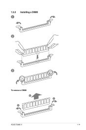
1.5.3 1 Installing a DIMM 2 3 To remove a DIMM B A A ASUS F2A85-V 1-19
1.5.3 1 Installing a DIMM 2 3 To remove a DIMM B A A ASUS F2A85-V 1-19
F2A85-V User's Manual
Page 33
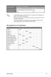
... USB OHCI 1/2/3/4 OnChip USB EHCI 1/2/3 OnChip USB XHCI 1 OnChip USB XHCI 2 HD Audio PCI_1 PCI_2 PCI_3 A B C D E F G shared - - - - - - - - shared shared - - - - - - shared - - - shared - - - shared - shared - - - - - - - - - - - - - - - - - - - - - - - - - - - - - - shared - - shared ASUS F2A85-V 1-21
... USB OHCI 1/2/3/4 OnChip USB EHCI 1/2/3 OnChip USB XHCI 1 OnChip USB XHCI 2 HD Audio PCI_1 PCI_2 PCI_3 A B C D E F G shared - - - - - - - - shared shared - - - - - - shared - - - shared - - - shared - shared - - - - - - - - - - - - - - - - - - - - - - - - - - - - - - shared - - shared ASUS F2A85-V 1-21
F2A85-V User's Manual
Page 35
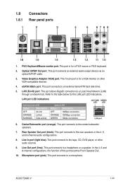
...) port. This port allows Gigabit connection to a headphone or a speaker. Center/Subwoofer port (orange). This port connects to a Local Area Network (LAN) through a network hub. ASUS F2A85-V 1-23 This port connects to the center/subwoofer speakers. 7. This port connects to an external Serial ATA hard disk drive. 5. Line Out port (lime). This...
...) port. This port allows Gigabit connection to a headphone or a speaker. Center/Subwoofer port (orange). This port connects to a Local Area Network (LAN) through a network hub. ASUS F2A85-V 1-23 This port connects to the center/subwoofer speakers. 7. This port connects to an external Serial ATA hard disk drive. 5. Line Out port (lime). This...
F2A85-V User's Manual
Page 37
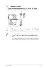
...FAN PWR GND CHA FAN DC Mode CHA FAN IN CHA FAN PWR GND F2A85-V CHA_FAN1 GND CHA FAN PWR CHA FAN IN CHA FAN DC Mode F2A85-V Fan connectors DO NOT forget to connect the fan cables to the fan ...connectors on the fan connectors. • The CPU_FAN connector supports a CPU fan of maximum 2A (24 W) fan power. • Only the CPU_FAN and CHA_FAN1/2 connectors support the ASUS ...pin CPU_FAN, and 4-pin CHA_FAN1/2) Connect the fan cables to the fan connectors. 1.8.2 Internal connectors 1. ASUS F2A85-V 1-25
...FAN PWR GND CHA FAN DC Mode CHA FAN IN CHA FAN PWR GND F2A85-V CHA_FAN1 GND CHA FAN PWR CHA FAN IN CHA FAN DC Mode F2A85-V Fan connectors DO NOT forget to connect the fan cables to the fan ...connectors on the fan connectors. • The CPU_FAN connector supports a CPU fan of maximum 2A (24 W) fan power. • Only the CPU_FAN and CHA_FAN1/2 connectors support the ASUS ...pin CPU_FAN, and 4-pin CHA_FAN1/2) Connect the fan cables to the fan connectors. 1.8.2 Internal connectors 1. ASUS F2A85-V 1-25
F2A85-V User's Manual
Page 39
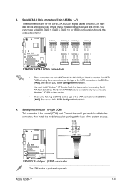
... in the BIOS to a slot opening at the back of the SATA connectors in the BIOS to AHCI mode by default. ASUS F2A85-V 1-27 SATA6G_4 SATA6G_5 SATA6G_6 SATA6G_7 GND RSATA_TXP7 RSATA_TXN7 GND RSATA_RXN7 RSATA_RXP7 GND GND RSATA_TXP6 RSATA_TXN6 GND RSATA_RXN6 RSATA_RXP6 GND GND RSATA_TXP5 RSATA_TXN5...0, RAID 1, RAID 5, RAID 10, or JBOD configuration through the onboard controller. COM PIN 1 RXD DTR DSR CTS DCD TXD GND RTS RI F2A85-V F2A85-V Serial port (COM) connector The COM module is for details. • You must install Windows® XP Service Pack 3 or later version ...
... in the BIOS to a slot opening at the back of the SATA connectors in the BIOS to AHCI mode by default. ASUS F2A85-V 1-27 SATA6G_4 SATA6G_5 SATA6G_6 SATA6G_7 GND RSATA_TXP7 RSATA_TXN7 GND RSATA_RXN7 RSATA_RXP7 GND GND RSATA_TXP6 RSATA_TXN6 GND RSATA_RXN6 RSATA_RXP6 GND GND RSATA_TXP5 RSATA_TXN5...0, RAID 1, RAID 5, RAID 10, or JBOD configuration through the onboard controller. COM PIN 1 RXD DTR DSR CTS DCD TXD GND RTS RI F2A85-V F2A85-V Serial port (COM) connector The COM module is for details. • You must install Windows® XP Service Pack 3 or later version ...
F2A85-V User's Manual
Page 41
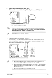
... a high definition front panel audio module to this connector, set the Front Panel Type item in the BIOS to [HD]. ASUS F2A85-V 1-29 6. Digital audio connector (4-1 pin SPDIF_OUT) This connector is for an additional Sony/Philips Digital Interface (S/PDIF) port. +5V SPDIFOUT GND... F2A85-V SPDIF_OUT F2A85-V Digital audio connector Ensure that the audio device of Sound playback is for details. • The front panel audio I /O module cable...
... a high definition front panel audio module to this connector, set the Front Panel Type item in the BIOS to [HD]. ASUS F2A85-V 1-29 6. Digital audio connector (4-1 pin SPDIF_OUT) This connector is for an additional Sony/Philips Digital Interface (S/PDIF) port. +5V SPDIFOUT GND... F2A85-V SPDIF_OUT F2A85-V Digital audio connector Ensure that the audio device of Sound playback is for details. • The front panel audio I /O module cable...
F2A85-V User's Manual
Page 43
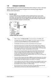
...switch does not function under Windows® OS environment. • During the tuning process, the system loads and tests failsafe memory settings. ASUS F2A85-V 1-31 1.9 Onboard switches Onboard switches allow you turn off the system and reinstall the DIMM before using the MemOK! It takes about 5-...DIMMs during POST reminding you download and update to the latest BIOS version from the ASUS website at www.asus.com. • If you to BIOS overclocking, press the MemOK! function. F2A85-V F2A85-V MemOK! Turn off the computer and unplug the power cord for about 30 seconds ...
...switch does not function under Windows® OS environment. • During the tuning process, the system loads and tests failsafe memory settings. ASUS F2A85-V 1-31 1.9 Onboard switches Onboard switches allow you turn off the system and reinstall the DIMM before using the MemOK! It takes about 5-...DIMMs during POST reminding you download and update to the latest BIOS version from the ASUS website at www.asus.com. • If you to BIOS overclocking, press the MemOK! function. F2A85-V F2A85-V MemOK! Turn off the computer and unplug the power cord for about 30 seconds ...
F2A85-V User's Manual
Page 45
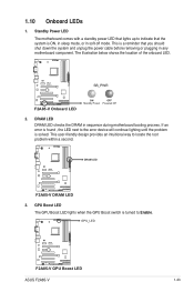
F2A85-V SB_PWR F2A85-V Onboard LED ON OFF Standby Power Powered Off 2. If an error is found , the LED next to the error device will continue lighting until the ... Boost LED The GPU Boost LED lights when the GPU Boost switch is solved. The illustration below shows the location of the onboard LED. F2A85-V DRAM LED F2A85-V DRAM LED 3. 1.10 Onboard LEDs 1. Standby Power LED The motherboard comes with a standby power LED that lights up to locate the root problem within...
F2A85-V SB_PWR F2A85-V Onboard LED ON OFF Standby Power Powered Off 2. If an error is found , the LED next to the error device will continue lighting until the ... Boost LED The GPU Boost LED lights when the GPU Boost switch is solved. The illustration below shows the location of the onboard LED. F2A85-V DRAM LED F2A85-V DRAM LED 3. 1.10 Onboard LEDs 1. Standby Power LED The motherboard comes with a standby power LED that lights up to locate the root problem within...
F2A85-V User's Manual
Page 48
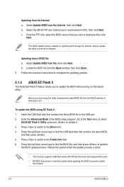
.... Press to switch to avail all its features. Updating from the ASUS website at www.asus.com. From the FTP site, select the BIOS version that contains the latest BIOS file to prevent system boot failure! 2-2 ASUS F2A85-V Always update the utility to the Drive field. 4. Enter the ...Advanced Mode of updating itself through the Internet. Select Update BIOS from the Open window, then click Open. 3. The ASUS Update utility is done. • This function ...
.... Press to switch to avail all its features. Updating from the ASUS website at www.asus.com. From the FTP site, select the BIOS version that contains the latest BIOS file to prevent system boot failure! 2-2 ASUS F2A85-V Always update the utility to the Drive field. 4. Enter the ...Advanced Mode of updating itself through the Internet. Select Update BIOS from the Open window, then click Open. 3. The ASUS Update utility is done. • This function ...
F2A85-V User's Manual
Page 50
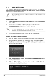
...SATA hard disk drives (optional). When the Make Disk menu appears, select the FreeDOS command prompt item by pressing the item number. 4. C:\>d: D:\> 2-4 ASUS F2A85-V The succeeding utility screens are for reference only. Download the latest BIOS file and BIOS Updater from Drive C (optical drive) to boot using defaults ... ESC to Drive D (USB flash drive). At the FreeDOS prompt, type d: and press to switch the disk from the ASUS website at http://support.asus.com and save the BIOS file and BIOS Updater to FreeDOS (http://www.freedos.org)! The actual utility screen displays may not...
...SATA hard disk drives (optional). When the Make Disk menu appears, select the FreeDOS command prompt item by pressing the item number. 4. C:\>d: D:\> 2-4 ASUS F2A85-V The succeeding utility screens are for reference only. Download the latest BIOS file and BIOS Updater from Drive C (optical drive) to boot using defaults ... ESC to Drive D (USB flash drive). At the FreeDOS prompt, type d: and press to switch the disk from the ASUS website at http://support.asus.com and save the BIOS file and BIOS Updater to FreeDOS (http://www.freedos.org)! The actual utility screen displays may not...

F2A85-V User's Manual
Page 52
... this motherboard apply for reference purposes only, and may not exactly match what you see on . If you in the EZ Mode/Advanced Mode screen. 2-6 ASUS F2A85-V See section 2.9 Exit Menu. • If the system fails to boot after changing any BIOS settings, load the default settings to erase the RTC RAM...
... this motherboard apply for reference purposes only, and may not exactly match what you see on . If you in the EZ Mode/Advanced Mode screen. 2-6 ASUS F2A85-V See section 2.9 Exit Menu. • If the system fails to boot after changing any BIOS settings, load the default settings to erase the RTC RAM...
F2A85-V User's Manual
Page 54
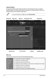
... figure below shows an example of the screen has the following sections for the detailed configurations. To access the EZ Mode, click Exit, then select ASUS EZ Mode. Advanced Mode General help Exit Main Back Ai Tweaker Advanced Advanced\ Onboard Devices Configuration > Monitor HD Audio Device Front Panel Type Enabled HD... to configure the BIOS settings. Advanced Mode The Advanced Mode provides advanced options for special functions For selecting the exit options and loading default settings 2-8 ASUS F2A85-V
... figure below shows an example of the screen has the following sections for the detailed configurations. To access the EZ Mode, click Exit, then select ASUS EZ Mode. Advanced Mode General help Exit Main Back Ai Tweaker Advanced Advanced\ Onboard Devices Configuration > Monitor HD Audio Device Front Panel Type Enabled HD... to configure the BIOS settings. Advanced Mode The Advanced Mode provides advanced options for special functions For selecting the exit options and loading default settings 2-8 ASUS F2A85-V
F2A85-V User's Manual
Page 56
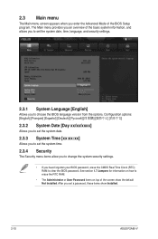
... The Security menu items allow you to change the system security settings. • If you enter the Advanced Mode of the screen show Installed. 2-10 ASUS F2A85-V 2.3 Main menu The Main menu screen appears when you have forgotten your BIOS password, erase the CMOS Real Time Clock (RTC) RAM to clear the...
... The Security menu items allow you to change the system security settings. • If you enter the Advanced Mode of the screen show Installed. 2-10 ASUS F2A85-V 2.3 Main menu The Main menu screen appears when you have forgotten your BIOS password, erase the CMOS Real Time Clock (RTC) RAM to clear the...


