
F2A55 User's Manual
Page 1
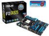
F2A55 Motherboard
F2A55 Motherboard
F2A55 User's Manual
Page 3
Contents Safety information...vi About this guide...vii F2A55 specifications summary ix Package contents...xii Chapter 1: Product introduction 1.1 Special features 1-1 1.1.1 Product highlights 1-1 1.1.2 ASUS DIGI+ VRM 1-1 1.1.3 ASUS Exclusive Features 1-2 1.2 Before you proceed 1-4 1.3 Motherboard overview 1-5 1.3.1 Placement direction 1-5 1.3.2 Screw holes 1-5 1.3.3 Motherboard layout 1-6 1.3.4 Layout contents 1-7 1.4 Accelerated Processing Unit (APU 1-7 1.4.1 APU installation 1-8 1.4.2 APU heatsink and fan assembly installation 1-9 1.5 System memory 1-11...
Contents Safety information...vi About this guide...vii F2A55 specifications summary ix Package contents...xii Chapter 1: Product introduction 1.1 Special features 1-1 1.1.1 Product highlights 1-1 1.1.2 ASUS DIGI+ VRM 1-1 1.1.3 ASUS Exclusive Features 1-2 1.2 Before you proceed 1-4 1.3 Motherboard overview 1-5 1.3.1 Placement direction 1-5 1.3.2 Screw holes 1-5 1.3.3 Motherboard layout 1-6 1.3.4 Layout contents 1-7 1.4 Accelerated Processing Unit (APU 1-7 1.4.1 APU installation 1-8 1.4.2 APU heatsink and fan assembly installation 1-9 1.5 System memory 1-11...
F2A55 User's Manual
Page 6
...your power supply is broken, do not try to the correct voltage in any damage, contact your area. vi Operation safety • Before installing the motherboard and adding devices on a stable surface. • If you detect any area where it may become wet. • Place the product on it... If you are not sure about the voltage of the electrical outlet you add a device. • Before connecting or removing signal cables from the motherboard, ensure that all power cables from the existing system before you are using, contact your local power company. • If the power supply is ...
...your power supply is broken, do not try to the correct voltage in any damage, contact your area. vi Operation safety • Before installing the motherboard and adding devices on a stable surface. • If you detect any area where it may become wet. • Place the product on it... If you are not sure about the voltage of the electrical outlet you add a device. • Before connecting or removing signal cables from the motherboard, ensure that all power cables from the existing system before you are using, contact your local power company. • If the power supply is ...
F2A55 User's Manual
Page 7
... guide This user guide contains the information you need when installing and configuring the motherboard. These documents are also provided. ASUS websites The ASUS website provides updated information on ASUS hardware and software products. vii Where to find more information Refer to change system... introduction This chapter describes the features of the standard package. Detailed descriptions of the BIOS parameters are not part of the motherboard and the new technology it supports. • Chapter 2: BIOS information This chapter tells how to the following sources for ...
... guide This user guide contains the information you need when installing and configuring the motherboard. These documents are also provided. ASUS websites The ASUS website provides updated information on ASUS hardware and software products. vii Where to find more information Refer to change system... introduction This chapter describes the features of the standard package. Detailed descriptions of the BIOS parameters are not part of the motherboard and the new technology it supports. • Chapter 2: BIOS information This chapter tells how to the following sources for ...
F2A55 User's Manual
Page 12
... PCIEX16_2 AMD® A55 ALC 887 SPDIF_OUT AAFP PCI2 64Mb BIOS PCI3 COM CLRTC USB78 USB910 SATA3G_1 SATA3G_2 SATA3G_3 SATA3G_4 SB_PWR USB1112 PANEL SATA3G_5 SATA3G_6 ASUS F2A55 motherboard User Guide 2 x Serial ATA 3.0 Gb/s cables 1 x I/O Shield User Guide Support DVD • If any of the above are for the following items. SOCKET FM2 DDR3... USB34 USB3_E12 LAN_USB12 AUDIO ASM 1042 CHA_FAN1 MemOK! Package contents Check your retailer. • The illustrated items above items is damaged or missing, contact your motherboard package for reference only.
... PCIEX16_2 AMD® A55 ALC 887 SPDIF_OUT AAFP PCI2 64Mb BIOS PCI3 COM CLRTC USB78 USB910 SATA3G_1 SATA3G_2 SATA3G_3 SATA3G_4 SB_PWR USB1112 PANEL SATA3G_5 SATA3G_6 ASUS F2A55 motherboard User Guide 2 x Serial ATA 3.0 Gb/s cables 1 x I/O Shield User Guide Support DVD • If any of the above are for the following items. SOCKET FM2 DDR3... USB34 USB3_E12 LAN_USB12 AUDIO ASM 1042 CHA_FAN1 MemOK! Package contents Check your retailer. • The illustrated items above items is damaged or missing, contact your motherboard package for reference only.
F2A55 User's Manual
Page 13
... High-quality Conductive Polymer Capacitors This motherboard uses all high-quality conductive polymer capacitors for durability, improved lifespan, and enhanced thermal capacity. 1.1.2 ASUS DIGI+ VRM DIGI+ Power Control: Digital Power Design for the APU* ASUS motherboards using user-defined profiles. Engineered and... combines processing power and advanced DirectX 11 graphics in FM2 socket compatible CPUs ASUS F2A55 1-1 The effect is adjusted via either carefully developed automated modes, or by world-renowned ASUS quality, it creates an ideal computing platform for the APU, called DIGI+...
... High-quality Conductive Polymer Capacitors This motherboard uses all high-quality conductive polymer capacitors for durability, improved lifespan, and enhanced thermal capacity. 1.1.2 ASUS DIGI+ VRM DIGI+ Power Control: Digital Power Design for the APU* ASUS motherboards using user-defined profiles. Engineered and... combines processing power and advanced DirectX 11 graphics in FM2 socket compatible CPUs ASUS F2A55 1-1 The effect is adjusted via either carefully developed automated modes, or by world-renowned ASUS quality, it creates an ideal computing platform for the APU, called DIGI+...
F2A55 User's Manual
Page 14
... provides you to simply press a button to -use helpful utilities. 1-2 Chapter 1: Product introduction ASUS Anti-Surge Protection This special design protects expensive devices and the motherboard from damage caused by power surges from switching power supply unit (PSU). ASUS UEFI BIOS includes the following new features: • F12 BIOS snapshot hotkey • F3...
... provides you to simply press a button to -use helpful utilities. 1-2 Chapter 1: Product introduction ASUS Anti-Surge Protection This special design protects expensive devices and the motherboard from damage caused by power surges from switching power supply unit (PSU). ASUS UEFI BIOS includes the following new features: • F12 BIOS snapshot hotkey • F3...
F2A55 User's Manual
Page 15
...ready The motherboard is an auto-recovery tool that allows you can not only easily charge iPod, iPhone and iPad, but also BC 1.1** standard mobile devices three times*** as fast as before. * Ai Charger is in regards to energy consumptions. ASUS CrashFree BIOS 3 ASUS CrashFree BIOS...environment-friendly and energyefficient products through product design and innovation to reduce carbon footprint of USB3.0 fast charging experience. ASUS F2A55 1-3 C.P.R. Ai Charger+ ASUS Ai Charger+, the latest Ai Charger* version, brings you to update the BIOS without using the bundled support DVD...
...ready The motherboard is an auto-recovery tool that allows you can not only easily charge iPod, iPhone and iPad, but also BC 1.1** standard mobile devices three times*** as fast as before. * Ai Charger is in regards to energy consumptions. ASUS CrashFree BIOS 3 ASUS CrashFree BIOS...environment-friendly and energyefficient products through product design and innovation to reduce carbon footprint of USB3.0 fast charging experience. ASUS F2A55 1-3 C.P.R. Ai Charger+ ASUS Ai Charger+, the latest Ai Charger* version, brings you to update the BIOS without using the bundled support DVD...
F2A55 User's Manual
Page 16
..., place it on a grounded antistatic pad or in the bag that came with the component. • Before you install motherboard components or change any motherboard settings. • Unplug the power cord from the wall socket before touching any component. • Before handling components, use..., such as the power supply case, to avoid damaging them due to static electricity. • Hold components by the edges to the motherboard, peripherals, or components. 1-4 Chapter 1: Product introduction 1.2 Before you proceed Take note of the following precautions before you install or remove any...
..., place it on a grounded antistatic pad or in the bag that came with the component. • Before you install motherboard components or change any motherboard settings. • Unplug the power cord from the wall socket before touching any component. • Before handling components, use..., such as the power supply case, to avoid damaging them due to static electricity. • Hold components by the edges to the motherboard, peripherals, or components. 1-4 Chapter 1: Product introduction 1.2 Before you proceed Take note of the following precautions before you install or remove any...
F2A55 User's Manual
Page 17
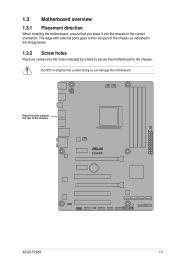
1.3 Motherboard overview 1.3.1 Placement direction When installing the motherboard, ensure that you place it into the holes indicated by circles to secure the motherboard to the rear part of the chassis. Doing so can damage the motherboard. F2A55 ASUS F2A55 1-5 The edge with external ports goes to the chassis. DO NOT overtighten the screws! Place this side towards the rear of the chassis as indicated in the image below. 1.3.2 Screw holes Place six screws into the chassis in the correct orientation.
1.3 Motherboard overview 1.3.1 Placement direction When installing the motherboard, ensure that you place it into the holes indicated by circles to secure the motherboard to the rear part of the chassis. Doing so can damage the motherboard. F2A55 ASUS F2A55 1-5 The edge with external ports goes to the chassis. DO NOT overtighten the screws! Place this side towards the rear of the chassis as indicated in the image below. 1.3.2 Screw holes Place six screws into the chassis in the correct orientation.
F2A55 User's Manual
Page 19
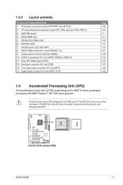
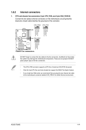
...pin SPDIF_OUT) Page 1-26 1-25 1-7 1-11 1-32 1-31 1-32 1-27 1-28 1-30 1-22 1-27 1-29 1-29 1.4 Accelerated Processing Unit (APU) This motherboard comes with an FM2 socket designed for the FM2 socket. DRAM LED (DRAM_LED) 6. switch 7. DO NOT force the APU into the socket to prevent bending...HD 7000 series graphics. AMD FM2 socket 4. 1.3.4 Layout contents Connectors/Jumpers/Slots/LED 1. System panel connector (20-8 pin PANEL) 10. F2A55 F2A55 CPU socket FM2 ASUS F2A55 1-7 Front panel audio connector (10-1 pin AAFP) 14. USB 2.0 connectors (10-1 pin USB78, USB910, USB1112) 11.
...pin SPDIF_OUT) Page 1-26 1-25 1-7 1-11 1-32 1-31 1-32 1-27 1-28 1-30 1-22 1-27 1-29 1-29 1.4 Accelerated Processing Unit (APU) This motherboard comes with an FM2 socket designed for the FM2 socket. DRAM LED (DRAM_LED) 6. switch 7. DO NOT force the APU into the socket to prevent bending...HD 7000 series graphics. AMD FM2 socket 4. 1.3.4 Layout contents Connectors/Jumpers/Slots/LED 1. System panel connector (20-8 pin PANEL) 10. F2A55 F2A55 CPU socket FM2 ASUS F2A55 1-7 Front panel audio connector (10-1 pin AAFP) 14. USB 2.0 connectors (10-1 pin USB78, USB910, USB1112) 11.
F2A55 User's Manual
Page 23
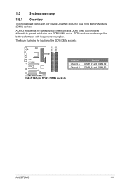
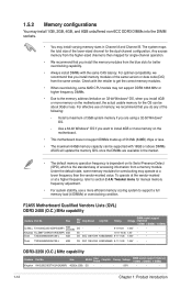
1.5 System memory 1.5.1 Overview This motherboard comes with less power consumption. A DDR3 module has the same physical dimensions as a DDR2 DIMM but is notched differently to prevent installation on a DDR2 DIMM socket. DDR3 modules are developed for better performance with four Double Data Rate 3 (DDR3) Dual Inline Memory Modules (DIMM) sockets. The figure illustrates the location of the DDR3 DIMM sockets: DIMM_A1 DIMM_A2 DIMM_B1 DIMM_B2 Channel Sockets F2A55 Channel A DIMM_A1 and DIMM_A2 Channel B DIMM_B1 and DIMM_B2 F2A55 240-pin DDR3 DIMM sockets ASUS F2A55 1-11
1.5 System memory 1.5.1 Overview This motherboard comes with less power consumption. A DDR3 module has the same physical dimensions as a DDR2 DIMM but is notched differently to prevent installation on a DDR2 DIMM socket. DDR3 modules are developed for better performance with four Double Data Rate 3 (DDR3) Dual Inline Memory Modules (DIMM) sockets. The figure illustrates the location of the DDR3 DIMM sockets: DIMM_A1 DIMM_A2 DIMM_B1 DIMM_B2 Channel Sockets F2A55 Channel A DIMM_A1 and DIMM_A2 Channel B DIMM_B1 and DIMM_B2 F2A55 240-pin DDR3 DIMM sockets ASUS F2A55 1-11
F2A55 User's Manual
Page 24
For optimal compatibility, we recommend that you install the memory modules from the same vendor. F2A55 Motherboard Qualified Vendors Lists (QVL) DDR3 2400 (O.C.) MHz capability Vendors Part No. Check with the retailer to get the correct memory modules. • When ...or more efficient memory cooling system to section 2.4 Ai Tweaker menu for better overclocking capability. • Always install DIMMs with 16GB or above DIMMs. ASUS will update the memory QVL once the DIMMs are available in Channel A and Channel B. KHX2250C9D3T1K2/4GX(XMP) Size 4GB(2x 2GB) SS/DS Chip...
For optimal compatibility, we recommend that you install the memory modules from the same vendor. F2A55 Motherboard Qualified Vendors Lists (QVL) DDR3 2400 (O.C.) MHz capability Vendors Part No. Check with the retailer to get the correct memory modules. • When ...or more efficient memory cooling system to section 2.4 Ai Tweaker menu for better overclocking capability. • Always install DIMMs with 16GB or above DIMMs. ASUS will update the memory QVL once the DIMMs are available in Channel A and Channel B. KHX2250C9D3T1K2/4GX(XMP) Size 4GB(2x 2GB) SS/DS Chip...
F2A55 User's Manual
Page 32
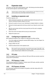
..., ensure that the drivers support "Share IRQ" or that came with the PCI Express specifications. 1.6.5 PCI Express x16 slots This motherboard supports two PCI Express x16 graphics cards that they support. Replace the system cover. 1.6.2 Configuring an expansion card After installing the ...card to the card. 3. Turn on the slot. 5. 1.6 Expansion slots In the future, you may cause you physical injury and damage motherboard components. 1.6.1 Installing an expansion card To install an expansion card: 1. Before installing the expansion card, read the documentation that the cards do...
..., ensure that the drivers support "Share IRQ" or that came with the PCI Express specifications. 1.6.5 PCI Express x16 slots This motherboard supports two PCI Express x16 graphics cards that they support. Replace the system cover. 1.6.2 Configuring an expansion card After installing the ...card to the card. 3. Turn on the slot. 5. 1.6 Expansion slots In the future, you may cause you physical injury and damage motherboard components. 1.6.1 Installing an expansion card To install an expansion card: 1. Before installing the expansion card, read the documentation that the cards do...
F2A55 User's Manual
Page 33
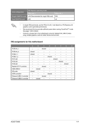
shared - - - PCI2 slot - - - - - HD audio shared - - - - - - - shared - - - - shared - - - - - ASUS F2A55 1-21 IRQ assignments for better thermal environment. PCIEx1_2 - - - Realtek 8111F controller - - See page 1-26 for details. • Connect a chassis fan to get better performance. • ... card) x16 PCIe x16_2 N/A x4 • In single VGA card mode, use the PCIe 2.0 x16_1 slot (blue) for a PCI Express x16 graphics card to the motherboard connector labeled CHA_FAN1/2 when using multiple graphics cards for this...
shared - - - PCI2 slot - - - - - HD audio shared - - - - - - - shared - - - - shared - - - - - ASUS F2A55 1-21 IRQ assignments for better thermal environment. PCIEx1_2 - - - Realtek 8111F controller - - See page 1-26 for details. • Connect a chassis fan to get better performance. • ... card) x16 PCIe x16_2 N/A x4 • In single VGA card mode, use the PCIe 2.0 x16_1 slot (blue) for a PCI Express x16 graphics card to the motherboard connector labeled CHA_FAN1/2 when using multiple graphics cards for this...
F2A55 User's Manual
Page 37
...not jumpers! ASUS F2A55 1-25 Insufficient air flow inside the system may damage the motherboard components. CHA_FAN2 CPU_FAN CHA_FAN1 F2A55 F2A55 Fan connectors DO NOT forget to connect the fan cables to the motherboard connector labeled CHA_FAN1/2 for better thermal environment. DO NOT place jumper caps on the motherboard, ensuring that... the black wire of each cable matches the ground pin of maximum 2A (24 W) fan power. • Only the 4-pin CPU fan and 4-pin chassis fan support the ASUS Fan Xpert+ feature. • If ...
...not jumpers! ASUS F2A55 1-25 Insufficient air flow inside the system may damage the motherboard components. CHA_FAN2 CPU_FAN CHA_FAN1 F2A55 F2A55 Fan connectors DO NOT forget to connect the fan cables to the motherboard connector labeled CHA_FAN1/2 for better thermal environment. DO NOT place jumper caps on the motherboard, ensuring that... the black wire of each cable matches the ground pin of maximum 2A (24 W) fan power. • Only the 4-pin CPU fan and 4-pin chassis fan support the ASUS Fan Xpert+ feature. • If ...
F2A55 User's Manual
Page 41
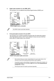
...or AC`97 audio standard. See section 2.5.5 Onboard Devices Configuration for details. • The front panel audio I/O module is purchased separately. 7. ASUS F2A55 1-29 Digital audio connector (4-1 pin SPDIF_OUT) This connector is for a chassis-mounted front panel audio I /O module cable to [HD]. Front ... F2A55 Digital audio connector The S/PDIF module is purchased separately. Connect one end of the front panel audio I /O module that you connect a high-definition front panel audio module to this connector to avail of the motherboard high-definition audio capability. • If you...
...or AC`97 audio standard. See section 2.5.5 Onboard Devices Configuration for details. • The front panel audio I/O module is purchased separately. 7. ASUS F2A55 1-29 Digital audio connector (4-1 pin SPDIF_OUT) This connector is for a chassis-mounted front panel audio I /O module cable to [HD]. Front ... F2A55 Digital audio connector The S/PDIF module is purchased separately. Connect one end of the front panel audio I /O module that you connect a high-definition front panel audio module to this connector to avail of the motherboard high-definition audio capability. • If you...
F2A55 User's Manual
Page 42
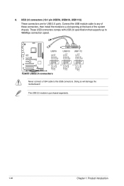
USB 2.0 connectors (10-1 pin USB78, USB910, USB1112) These connectors are for USB 2.0 ports. Doing so will damage the motherboard! Connect the USB module cable to any of the system chassis. The USB 2.0 module is purchased separately. 1-30 Chapter 1: Product introduction ...USB_P8USB_P8+ GND NC USB+5V USB_P10USB_P10+ GND NC USB+5V USB_P12USB_P12+ GND NC USB78 USB910 USB1112 F2A55 PIN 1 PIN 1 PIN 1 USB+5V USB_P7USB_P7+ GND USB+5V USB_P9USB_P9+ GND USB+5V USB_P11USB_P11+ GND F2A55 USB2.0 connectors Never connect a 1394 cable to a slot opening at the back of these connectors,...
USB 2.0 connectors (10-1 pin USB78, USB910, USB1112) These connectors are for USB 2.0 ports. Doing so will damage the motherboard! Connect the USB module cable to any of the system chassis. The USB 2.0 module is purchased separately. 1-30 Chapter 1: Product introduction ...USB_P8USB_P8+ GND NC USB+5V USB_P10USB_P10+ GND NC USB+5V USB_P12USB_P12+ GND NC USB78 USB910 USB1112 F2A55 PIN 1 PIN 1 PIN 1 USB+5V USB_P7USB_P7+ GND USB+5V USB_P9USB_P9+ GND USB+5V USB_P11USB_P11+ GND F2A55 USB2.0 connectors Never connect a 1394 cable to a slot opening at the back of these connectors,...
F2A55 User's Manual
Page 43
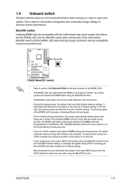
...allow you to fine-tune performance when working on the computer. F2A55 F2A55 MemOK! switch • Refer to the latest BIOS version from the ASUS website at www.asus.com after using the MemOK! Replace the DIMMs with the motherboard may cause system boot failure, and the DRAM_LED near the MemOK...! MemOK! switch Installing DIMMs that the BIOS has been restored to boot and load BIOS default settings. Press and hold the MemOK! Turn off the system and reinstall the DIMM before using the MemOK! ASUS F2A55 ...
...allow you to fine-tune performance when working on the computer. F2A55 F2A55 MemOK! switch • Refer to the latest BIOS version from the ASUS website at www.asus.com after using the MemOK! Replace the DIMMs with the motherboard may cause system boot failure, and the DRAM_LED near the MemOK...! MemOK! switch Installing DIMMs that the BIOS has been restored to boot and load BIOS default settings. Press and hold the MemOK! Turn off the system and reinstall the DIMM before using the MemOK! ASUS F2A55 ...
F2A55 User's Manual
Page 44
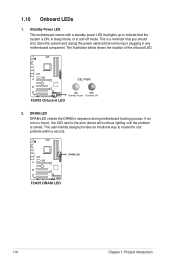
This is a reminder that the system is ON, in sleep mode, or in any motherboard component. F2A55 SB_PWR F2A55 Onboard LED ON OFF Standby Power Powered Off 2. Standby Power LED The motherboard comes with a standby power LED that lights up to indicate that you should shut down the system and unplug ... soft-off mode. The illustration below shows the location of the onboard LED. DRAM LED DRAM LED checks the DRAM in sequence during motherboard booting process. If an error is solved. This user-friendly design provides an intuitional way to the error device will continue lighting until ...
This is a reminder that the system is ON, in sleep mode, or in any motherboard component. F2A55 SB_PWR F2A55 Onboard LED ON OFF Standby Power Powered Off 2. Standby Power LED The motherboard comes with a standby power LED that lights up to indicate that you should shut down the system and unplug ... soft-off mode. The illustration below shows the location of the onboard LED. DRAM LED DRAM LED checks the DRAM in sequence during motherboard booting process. If an error is solved. This user-friendly design provides an intuitional way to the error device will continue lighting until ...


