F1A55 R2.0 User's Manual
Page 12
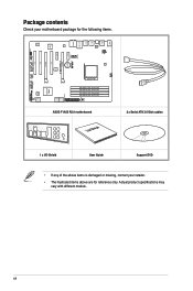
...of the above items is damaged or missing, contact your retailer. • The illustrated items above are for reference only. DRAM_LED EATXPWR ASUS F1A55 R2.0 motherboard User Manual 2 x Serial ATA 3.0 Gb/s cables 1 x I /O ALC 887 AAFP ATX12V CHA_FAN1 PWR_FAN PCIEX1_1 PCIEX1_2 PCI3 ...COM1 SPDIF_OUT CPU_FAN EPU Lithium Cell CMOS Power PCIEX16_1 F1A55 R2.0 PCI1 PCIEX16_2 PCI2 USB1112 USB910 64Mb BIOS USB78 CHA_FAN2 CLRTC SB_PWR PANEL SATA3G_1 SATA3G_2 AMD® A55 FCH ICS483A SATA3G_3 SATA3G_5 ...
...of the above items is damaged or missing, contact your retailer. • The illustrated items above are for reference only. DRAM_LED EATXPWR ASUS F1A55 R2.0 motherboard User Manual 2 x Serial ATA 3.0 Gb/s cables 1 x I /O ALC 887 AAFP ATX12V CHA_FAN1 PWR_FAN PCIEX1_1 PCIEX1_2 PCI3 ...COM1 SPDIF_OUT CPU_FAN EPU Lithium Cell CMOS Power PCIEX16_1 F1A55 R2.0 PCI1 PCIEX16_2 PCI2 USB1112 USB910 64Mb BIOS USB78 CHA_FAN2 CLRTC SB_PWR PANEL SATA3G_1 SATA3G_2 AMD® A55 FCH ICS483A SATA3G_3 SATA3G_5 ...
F1A55 R2.0 User's Manual
Page 13
... 3.0 transfers data 10x faster and is designed to support up to connect easily with a real-time 3D-rendered previews within ATI Catalyst™ Control Center. ASUS F1A55 R2.0 1-1 It features Dual-channel DDR3 memory support and accelerates data transfer rate up to enable accelerated performance and an industry-leading visual experience. This revolutionary...
... 3.0 transfers data 10x faster and is designed to support up to connect easily with a real-time 3D-rendered previews within ATI Catalyst™ Control Center. ASUS F1A55 R2.0 1-1 It features Dual-channel DDR3 memory support and accelerates data transfer rate up to enable accelerated performance and an industry-leading visual experience. This revolutionary...
F1A55 R2.0 User's Manual
Page 15
... to adjust the CPU fan and chassis fan speeds according to different ambient temperatures caused by turning your favorite photos into 256-color boot logos. ASUS TurboV Feel the adrenaline rush of fan speed to restore a corrupted BIOS file using a bootable floppy disk or an OS-based utility. settings in ... iPods, iPhones and iPads. ** Check your USB mobile device manufacturer if it fully supports the BC 1.1 function. *** The actual charging speed may vary with the ASUS TurboV. With its user-friendly interface makes overclocking only a few clicks away. ASUS F1A55 R2.0 1-3
... to adjust the CPU fan and chassis fan speeds according to different ambient temperatures caused by turning your favorite photos into 256-color boot logos. ASUS TurboV Feel the adrenaline rush of fan speed to restore a corrupted BIOS file using a bootable floppy disk or an OS-based utility. settings in ... iPods, iPhones and iPads. ** Check your USB mobile device manufacturer if it fully supports the BC 1.1 function. *** The actual charging speed may vary with the ASUS TurboV. With its user-friendly interface makes overclocking only a few clicks away. ASUS F1A55 R2.0 1-3
F1A55 R2.0 User's Manual
Page 17
... do so can cause you physical injury and damage motherboard components. 1.3.1 Placement direction When installing the motherboard, place it into the chassis in the image. ASUS F1A55 R2.0 1-5 Ensure that you unplug the power cord before touching any component. • Before handling components, use a grounded wrist strap or touch a safely grounded object or...
... do so can cause you physical injury and damage motherboard components. 1.3.1 Placement direction When installing the motherboard, place it into the chassis in the image. ASUS F1A55 R2.0 1-5 Ensure that you unplug the power cord before touching any component. • Before handling components, use a grounded wrist strap or touch a safely grounded object or...
F1A55 R2.0 User's Manual
Page 21
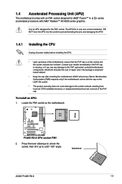
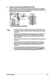
... 90°-100° angle. ASUS will process Return Merchandise Authorization (RMA) requests only if the motherboard comes with AMD® Radeon™ HD 6000 series graphics. To install an APU: 1. Contact your retailer immediately if the PnP cap is on the motherboard. F1A55 R2.0 F1A55 R2.0 CPU socket FM1 2. Press the...; Upon purchase of the PnP cap. Locate the FM1 socket on the socket and the socket contacts are not bent. Socket lever ASUS F1A55 R2.0 1-9 1.4 Accelerated Processing Unit (APU) This motherboard comes with an FM1 socket designed for the FM1 socket.
... 90°-100° angle. ASUS will process Return Merchandise Authorization (RMA) requests only if the motherboard comes with AMD® Radeon™ HD 6000 series graphics. To install an APU: 1. Contact your retailer immediately if the PnP cap is on the motherboard. F1A55 R2.0 F1A55 R2.0 CPU socket FM1 2. Press the...; Upon purchase of the PnP cap. Locate the FM1 socket on the socket and the socket contacts are not bent. Socket lever ASUS F1A55 R2.0 1-9 1.4 Accelerated Processing Unit (APU) This motherboard comes with an FM1 socket designed for the FM1 socket.
F1A55 R2.0 User's Manual
Page 23
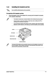
... base. • The retention module base is already installed on the motherboard upon purchase. • You do not match the CPU documentation, follow the latter. ASUS F1A55 R2.0 1-11 1.4.2 Installing the heatsink and fan Use only AMD-certified heatsink and fan assemblies. CPU Fan CPU Heatsink Retention bracket Retention Module Base Retention bracket...
... base. • The retention module base is already installed on the motherboard upon purchase. • You do not match the CPU documentation, follow the latter. ASUS F1A55 R2.0 1-11 1.4.2 Installing the heatsink and fan Use only AMD-certified heatsink and fan assemblies. CPU Fan CPU Heatsink Retention bracket Retention Module Base Retention bracket...
F1A55 R2.0 User's Manual
Page 25
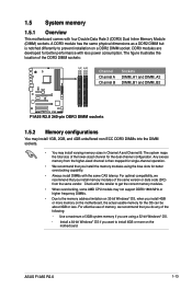
...-channel configuration. Use a maximum of 3GB system memory if you install the memory modules using a 32-bit Windows® OS. - ASUS F1A55 R2.0 1-13 The figure illustrates the location of the lower-sized channel for better performance with four Double Data Rate 3 (DDR3) Dual Inline...the total size of the DDR3 DIMM sockets: DIMM_A1 DIMM_A2 DIMM_B1 DIMM_B2 Channel Channel A Channel B Sockets DIMM_A1 and DIMM_A2 DIMM_B1 and DIMM_B2 F1A55 R2.0 F1A55 R2.0 240-pin DDR3 DIMM sockets 1.5.2 Memory configurations You may install 1GB, 2GB, and 4GB unbuffered non-ECC DDR3 DIMMs into the DIMM...
...-channel configuration. Use a maximum of 3GB system memory if you install the memory modules using a 32-bit Windows® OS. - ASUS F1A55 R2.0 1-13 The figure illustrates the location of the lower-sized channel for better performance with four Double Data Rate 3 (DDR3) Dual Inline...the total size of the DDR3 DIMM sockets: DIMM_A1 DIMM_A2 DIMM_B1 DIMM_B2 Channel Channel A Channel B Sockets DIMM_A1 and DIMM_A2 DIMM_B1 and DIMM_B2 F1A55 R2.0 F1A55 R2.0 240-pin DDR3 DIMM sockets 1.5.2 Memory configurations You may install 1GB, 2GB, and 4GB unbuffered non-ECC DDR3 DIMMs into the DIMM...
F1A55 R2.0 User's Manual
Page 27
... 1.65V • • • - - 8-8-8-24 1.7V • • • - - - 1.65V • • • - - 8-8-8-24 1.65V • • - - 9 - • • • (continued on the next page) ASUS F1A55 R2.0 1-15 Chip NO. Timing DIMM socket support Voltage (Optional) 1 DIMM 2 DIMMs 4 DIMMs - 9-9-9-24 1.65V • • • - 9-10-9-27 1.50V • • • - 9-10-9-28...
... 1.65V • • • - - 8-8-8-24 1.7V • • • - - - 1.65V • • • - - 8-8-8-24 1.65V • • - - 9 - • • • (continued on the next page) ASUS F1A55 R2.0 1-15 Chip NO. Timing DIMM socket support Voltage (Optional) 1 DIMM 2 DIMMs 4 DIMMs - 9-9-9-24 1.65V • • • - 9-10-9-27 1.50V • • • - 9-10-9-28...
F1A55 R2.0 User's Manual
Page 29
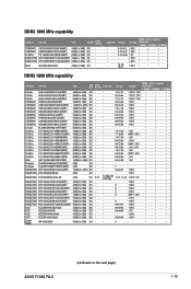
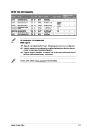
ASUS F1A55 R2.0 1-17 J1108EDSE-DJ-F - Visit the ASUS website at www.asus.com for the latest QVL. DDR3 1066 MHz capability Vendors Part No. DIMM socket support (Optional) 1 DIMM 2 DIMMs 4 DIMMs • • • • • • &#...
ASUS F1A55 R2.0 1-17 J1108EDSE-DJ-F - Visit the ASUS website at www.asus.com for the latest QVL. DDR3 1066 MHz capability Vendors Part No. DIMM socket support (Optional) 1 DIMM 2 DIMMs 4 DIMMs • • • • • • &#...
F1A55 R2.0 User's Manual
Page 31
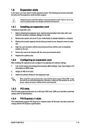
... with the PCI Express specifications. Install the software drivers for information on shared slots, ensure that the drivers support "Share IRQ" or that they support. ASUS F1A55 R2.0 1-19 Remove the bracket opposite the slot that you intend to the card. 3. Assign an IRQ to use . 4. Otherwise, conflicts will arise between the two...
... with the PCI Express specifications. Install the software drivers for information on shared slots, ensure that the drivers support "Share IRQ" or that they support. ASUS F1A55 R2.0 1-19 Remove the bracket opposite the slot that you intend to the card. 3. Assign an IRQ to use . 4. Otherwise, conflicts will arise between the two...
F1A55 R2.0 User's Manual
Page 33
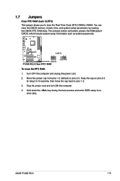
... back to pins 2-3. Hold down the key during the boot process and enter BIOS setup to reenter data. F1A55 R2.0 CLRTC 12 23 Normal (Default) F1A55 R2.0 Clear RTC RAM Clear RTC To erase the RTC RAM: 1. ASUS F1A55 R2.0 1-21 Turn OFF the computer and unplug the power cord. 2. Plug the power cord and turn ON...
... back to pins 2-3. Hold down the key during the boot process and enter BIOS setup to reenter data. F1A55 R2.0 CLRTC 12 23 Normal (Default) F1A55 R2.0 Clear RTC RAM Clear RTC To erase the RTC RAM: 1. ASUS F1A55 R2.0 1-21 Turn OFF the computer and unplug the power cord. 2. Plug the power cord and turn ON...
F1A55 R2.0 User's Manual
Page 35
.../Subwoofer Rear Speaker Out Side Speaker Out 9. Side Speaker Out port (gray). This port connects to the tape, CD, DVD player, or other audio sources. 6. ASUS F1A55 R2.0 1-23 This port connects to the rear speakers in the 8channel audio configuration. This port connects to the center/subwoofer speakers. 4. This port connects to...
.../Subwoofer Rear Speaker Out Side Speaker Out 9. Side Speaker Out port (gray). This port connects to the tape, CD, DVD player, or other audio sources. 6. ASUS F1A55 R2.0 1-23 This port connects to the rear speakers in the 8channel audio configuration. This port connects to the center/subwoofer speakers. 4. This port connects to...
F1A55 R2.0 User's Manual
Page 37
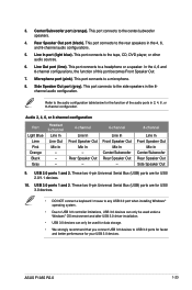
... unstable or may not boot up if the power is inadequate. • If you intend to connect the 4-pin ATX +12V power plug. ATX12V EATXPWR F1A55 R2.0 GND GND PIN 1 +12V DC +3 Volts +12V DC +12 Volts +12 Volts +5V Standby Power OK GND +5 Volts GND +5 Volts GND +3 Volts... +3 Volts PIN 1 F1A55 R2.0 ATX power connectors GND +5 Volts +5 Volts +5 Volts -5 Volts GND GND GND PSON# GND -12 Volts +3 Volts • We recommend that the 20-pin power plug can provide at http://support.asus. ASUS F1A55 R2.0 1-25
... unstable or may not boot up if the power is inadequate. • If you intend to connect the 4-pin ATX +12V power plug. ATX12V EATXPWR F1A55 R2.0 GND GND PIN 1 +12V DC +3 Volts +12V DC +12 Volts +12 Volts +5V Standby Power OK GND +5 Volts GND +5 Volts GND +3 Volts... +3 Volts PIN 1 F1A55 R2.0 ATX power connectors GND +5 Volts +5 Volts +5 Volts -5 Volts GND GND GND PSON# GND -12 Volts +3 Volts • We recommend that the 20-pin power plug can provide at http://support.asus. ASUS F1A55 R2.0 1-25
F1A55 R2.0 User's Manual
Page 39
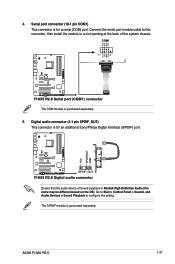
... port (COM1) connector The COM module is purchased separately. +5V SPDIFOUT GND ASUS F1A55 R2.0 1-27 The S/PDIF module is purchased separately. 5. F1A55 R2.0 SPDIF_OUT F1A55 R2.0 Digital audio connector Ensure that the audio device of the system chassis. RXD DTR DSR CTS DCD TXD GND RTS RI 4. Go to Start > Control ...
... port (COM1) connector The COM module is purchased separately. +5V SPDIFOUT GND ASUS F1A55 R2.0 1-27 The S/PDIF module is purchased separately. 5. F1A55 R2.0 SPDIF_OUT F1A55 R2.0 Digital audio connector Ensure that the audio device of the system chassis. RXD DTR DSR CTS DCD TXD GND RTS RI 4. Go to Start > Control ...
F1A55 R2.0 User's Manual
Page 41
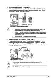
...NC NC MIC2 MICPWR Line out_R NC Line out_L PORT1 L PORT1 R PORT2 R SENSE_SEND PORT2 L F1A55 R2.0 AAFP PIN 1 HD-audio-compliant Legacy AC'97 pin definition compliant definition F1A55 R2.0 Front panel audio connector • We recommend that supports either a High Definition Audio or AC`... to avail of these connectors, then install the module to 480Mbps connection speed. ASUS F1A55 R2.0 1-29 USB1112 USB910 USB78 USB+5V USB_P8USB_P8+ GND NC USB+5V USB_P10USB_P10+ GND NC USB+5V USB_P12USB_P12+ GND NC F1A55 R2.0 PIN 1 PIN 1 PIN 1 USB+5V USB_P7USB_P7+ GND USB+5V USB_P9USB_P9...
...NC NC MIC2 MICPWR Line out_R NC Line out_L PORT1 L PORT1 R PORT2 R SENSE_SEND PORT2 L F1A55 R2.0 AAFP PIN 1 HD-audio-compliant Legacy AC'97 pin definition compliant definition F1A55 R2.0 Front panel audio connector • We recommend that supports either a High Definition Audio or AC`... to avail of these connectors, then install the module to 480Mbps connection speed. ASUS F1A55 R2.0 1-29 USB1112 USB910 USB78 USB+5V USB_P8USB_P8+ GND NC USB+5V USB_P10USB_P10+ GND NC USB+5V USB_P12USB_P12+ GND NC F1A55 R2.0 PIN 1 PIN 1 PIN 1 USB+5V USB_P7USB_P7+ GND USB+5V USB_P9USB_P9...
F1A55 R2.0 User's Manual
Page 43
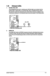
... OFF Standby Power Powered Off F1A55 R2.0 Onboard LED 2. This is ON, in sleep mode, or in soft-off mode. This user-friendly design provides an intuitive way to indicate that the ... LED next to the error device will light up to locate the root problem quickly. The illustration below shows the location of the onboard LED. F1A55 R2.0 DRAM LED F1A55 R2.0 DRAM LED ASUS F1A55 R2.0 1-31 1.10 Onboard LEDs 1.
... OFF Standby Power Powered Off F1A55 R2.0 Onboard LED 2. This is ON, in sleep mode, or in soft-off mode. This user-friendly design provides an intuitive way to indicate that the ... LED next to the error device will light up to locate the root problem quickly. The illustration below shows the location of the onboard LED. F1A55 R2.0 DRAM LED F1A55 R2.0 DRAM LED ASUS F1A55 R2.0 1-31 1.10 Onboard LEDs 1.
F1A55 R2.0 User's Manual
Page 45
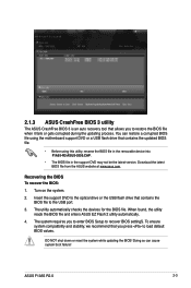
... II Quick Bar appears. 2. BIOS information 2.1 Managing and updating your BIOS 2 Save a copy of the following methods: ASUS F1A55 R2.0 2-1 Copy the original motherboard BIOS using this utility. Updating the BIOS To update the BIOS: 1. The ASUS Update main screen appears. From the list, select either through a network or an Internet Service Provider (ISP...
... II Quick Bar appears. 2. BIOS information 2.1 Managing and updating your BIOS 2 Save a copy of the following methods: ASUS F1A55 R2.0 2-1 Copy the original motherboard BIOS using this utility. Updating the BIOS To update the BIOS: 1. The ASUS Update main screen appears. From the list, select either through a network or an Internet Service Provider (ISP...
F1A55 R2.0 User's Manual
Page 47
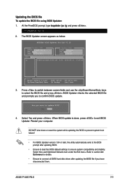
... utility, rename the BIOS file in the removable device into F1A55-R2-ASUS-0309.CAP. • The BIOS file in the support DVD may not be the latest version. Download the latest BIOS file from the ASUS website at www.asus.com. ASUS F1A55 R2.0 2-3 You can cause system boot failure! When found, ...the utility reads the BIOS file and enters ASUS EZ Flash 2 utility automatically. 4. DO NOT shut down or reset the system...
... utility, rename the BIOS file in the removable device into F1A55-R2-ASUS-0309.CAP. • The BIOS file in the support DVD may not be the latest version. Download the latest BIOS file from the ASUS website at www.asus.com. ASUS F1A55 R2.0 2-3 You can cause system boot failure! When found, ...the utility reads the BIOS file and enters ASUS EZ Flash 2 utility automatically. 4. DO NOT shut down or reset the system...
F1A55 R2.0 User's Manual
Page 49
... To update the BIOS file using BIOS Updater: 1. Refer to section 2.9 Exit menu for details. • Ensure to ensure system compatibility and stability. ASUS F1A55 R2.0 2-5 Restart your computer. DO NOT shut down or reset the system while updating the BIOS to prevent system boot failure! • For BIOS Updater ...prompt, type bupdater /pc /g and press . 2. BIOS Updater checks the selected BIOS file and prompts you have disconnected them. Select Yes and press . F1A55 R2.0 0309 F1A55-R2-ASUS-0309.CAP 8194 2012-05-16 15:25:48 3. The BIOS Updater screen appears as below.
... To update the BIOS file using BIOS Updater: 1. Refer to section 2.9 Exit menu for details. • Ensure to ensure system compatibility and stability. ASUS F1A55 R2.0 2-5 Restart your computer. DO NOT shut down or reset the system while updating the BIOS to prevent system boot failure! • For BIOS Updater ...prompt, type bupdater /pc /g and press . 2. BIOS Updater checks the selected BIOS file and prompts you have disconnected them. Select Yes and press . F1A55 R2.0 0309 F1A55-R2-ASUS-0309.CAP 8194 2012-05-16 15:25:48 3. The BIOS Updater screen appears as below.
F1A55 R2.0 User's Manual
Page 51
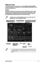
EZ Mode By default, the EZ Mode screen appears when you to select the display language, system performance mode and boot device priority. ASUS F1A55 R2.0 2-7 To access the Advanced Mode, click Exit/Advanced Mode, then select Advanced Mode. You can change modes from the Exit menu or from the Exit/...
EZ Mode By default, the EZ Mode screen appears when you to select the display language, system performance mode and boot device priority. ASUS F1A55 R2.0 2-7 To access the Advanced Mode, click Exit/Advanced Mode, then select Advanced Mode. You can change modes from the Exit menu or from the Exit/...


