User Manual
Page 1
Motherboard F1A55-M LX Series • F1A55-M LX • F1A55-M LX PLUS
Motherboard F1A55-M LX Series • F1A55-M LX • F1A55-M LX PLUS
User Manual
Page 8
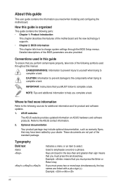
... documents are not part of the BIOS parameters are linked with a plus sign (+). Example: means that you must press the enclosed key. If you need when installing and configuring the motherboard. Conventions used throughout this manual. DANGER/WARNING: Information to prevent injury... phrase. NOTE: Tips and additional information to help you must press the Enter or Return key. ASUS websites The ASUS website provides updated information on ASUS hardware and software products. Detailed descriptions of the standard package. Where to find more keys simultaneously, the...
... documents are not part of the BIOS parameters are linked with a plus sign (+). Example: means that you must press the enclosed key. If you need when installing and configuring the motherboard. Conventions used throughout this manual. DANGER/WARNING: Information to prevent injury... phrase. NOTE: Tips and additional information to help you must press the Enter or Return key. ASUS websites The ASUS website provides updated information on ASUS hardware and software products. Detailed descriptions of the standard package. Where to find more keys simultaneously, the...
User Manual
Page 13
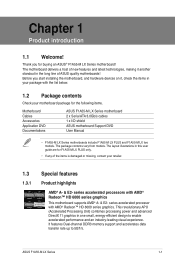
Before you for buying an ASUS® F1A55-M LX Series motherboard! series accelerated processor with the list below. 1.2 Package contents Check your motherboard package for F1A55-M LX PLUS only. • If any of ASUS quality motherboards! ASUS F1A55-M LX Series 1-1 It features Dual-channel DDR3 memory support and accelerates data transfer rate up to enable accelerated performance and an industry-leading visual experience. The...
Before you for buying an ASUS® F1A55-M LX Series motherboard! series accelerated processor with the list below. 1.2 Package contents Check your motherboard package for F1A55-M LX PLUS only. • If any of ASUS quality motherboards! ASUS F1A55-M LX Series 1-1 It features Dual-channel DDR3 memory support and accelerates data transfer rate up to enable accelerated performance and an industry-leading visual experience. The...
User Manual
Page 14
... 3D-rendered previews within ATI Catalyst™ Control Center. 100% All High-quality Conductive Polymer Capacitors (F1A55-M LX PLUS only) This motherboard uses all high-quality conductive polymer capacitors for durability, improved lifespan, and enhanced thermal capacity. 1.3.2 ASUS Exclusive Features Ai Charger Ai Charger is for experienced performance enthusiasts that goes beyond traditional keyboard-only...
... 3D-rendered previews within ATI Catalyst™ Control Center. 100% All High-quality Conductive Polymer Capacitors (F1A55-M LX PLUS only) This motherboard uses all high-quality conductive polymer capacitors for durability, improved lifespan, and enhanced thermal capacity. 1.3.2 ASUS Exclusive Features Ai Charger Ai Charger is for experienced performance enthusiasts that goes beyond traditional keyboard-only...
User Manual
Page 16
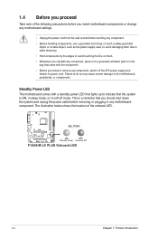
... with a standby power LED that you install or remove any motherboard component. This is ON, in sleep mode, or in any component, switch off mode. 1.4 Before you proceed Take note of the onboard LED. F1A55-M LX PLUS SB_PWR ON OFF Standby Power Powered Off F1A55-M LX PLUS Onboard LED 1-4 Chapter 1: Product introduction Failure to do so may...
... with a standby power LED that you install or remove any motherboard component. This is ON, in sleep mode, or in any component, switch off mode. 1.4 Before you proceed Take note of the onboard LED. F1A55-M LX PLUS SB_PWR ON OFF Standby Power Powered Off F1A55-M LX PLUS Onboard LED 1-4 Chapter 1: Product introduction Failure to do so may...
User Manual
Page 17
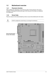
The edge with external ports goes to the chassis. F1A55-M LX PLUS ASUS F1A55-M LX Series 1-5 Doing so can damage the motherboard. Place this side towards the rear of the chassis as indicated in the correct orientation. 1.5 Motherboard overview 1.5.1 Placement direction When installing the motherboard, ensure that you place it into the chassis in the image below. 1.5.2 Screw holes Place six screws into the holes indicated by circles to secure the motherboard to the rear part of the chassis. DO NOT overtighten the screws!
The edge with external ports goes to the chassis. F1A55-M LX PLUS ASUS F1A55-M LX Series 1-5 Doing so can damage the motherboard. Place this side towards the rear of the chassis as indicated in the correct orientation. 1.5 Motherboard overview 1.5.1 Placement direction When installing the motherboard, ensure that you place it into the chassis in the image below. 1.5.2 Screw holes Place six screws into the holes indicated by circles to secure the motherboard to the rear part of the chassis. DO NOT overtighten the screws!
User Manual
Page 18
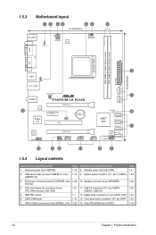
...-1 pin AAFP) 1-25 7. 1.5.3 Motherboard layout 1 2 34 54 6 21.3cm(8.4in) KB_USB56 KBPWR ATX12V EPU CPU_FAN COM1 SOCKET FM1 DDR3 DIMM_A1 (64bit, 240-pin module) DDR3 DIMM_B1 (64bit, 240-pin module) EATXPWR SATA3G_5 SATA3G_6 24.4cm(9.6in) LPT VGA 3 USB34 USBPW1-6 LAN1_USB12 AUDIO 14 RTL 8111E Super I/O CHA_FAN F1A55-M LX PLUS PCIEX16_1 PCIEX1_1 CLRTC PCI1...
...-1 pin AAFP) 1-25 7. 1.5.3 Motherboard layout 1 2 34 54 6 21.3cm(8.4in) KB_USB56 KBPWR ATX12V EPU CPU_FAN COM1 SOCKET FM1 DDR3 DIMM_A1 (64bit, 240-pin module) DDR3 DIMM_B1 (64bit, 240-pin module) EATXPWR SATA3G_5 SATA3G_6 24.4cm(9.6in) LPT VGA 3 USB34 USBPW1-6 LAN1_USB12 AUDIO 14 RTL 8111E Super I/O CHA_FAN F1A55-M LX PLUS PCIEX16_1 PCIEX1_1 CLRTC PCI1...
User Manual
Page 19
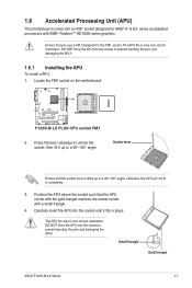
... a small triangle. 4. Small triangle Gold triangle ASUS F1A55-M LX Series 1-7 DO NOT force the APU into the socket until it up to prevent bending the pins and damaging the APU! 1.6 Accelerated Processing Unit (APU) This motherboard comes with an FM1 socket designed for the FM1... socket. Ensure that the APU corner with the gold triangle matches the socket corner with AMD® Radeon™ HD 6000 series graphics. F1A55-M LX PLUS F1A55-M LX PLUS CPU socket FM1 2. Position the...
... a small triangle. 4. Small triangle Gold triangle ASUS F1A55-M LX Series 1-7 DO NOT force the APU into the socket until it up to prevent bending the pins and damaging the APU! 1.6 Accelerated Processing Unit (APU) This motherboard comes with an FM1 socket designed for the FM1... socket. Ensure that the APU corner with the gold triangle matches the socket corner with AMD® Radeon™ HD 6000 series graphics. F1A55-M LX PLUS F1A55-M LX PLUS CPU socket FM1 2. Position the...
User Manual
Page 20
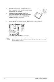
... if you fail to plug this connector. CPU_FAN F1A55-M LX PLUS F1A55-M LX PLUS CPU fan connector DO NOT forget to secure the APU. When the APU is locked. 6. Hardware monitoring errors can also refer to indicate that comes with the heatsink package. 5. The lever clicks on the motherboard. Connect the CPU fan cable to the CPU_FAN...
... if you fail to plug this connector. CPU_FAN F1A55-M LX PLUS F1A55-M LX PLUS CPU fan connector DO NOT forget to secure the APU. When the APU is locked. 6. Hardware monitoring errors can also refer to indicate that comes with the heatsink package. 5. The lever clicks on the motherboard. Connect the CPU fan cable to the CPU_FAN...
User Manual
Page 22
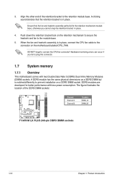
... mechanism to secure the heatsink and fan to plug this connector. 1.7 System memory 1.7.1 Overview This motherboard comes with less power consumption. When the fan and heatsink assembly is in place, connect the CPU...F1A55-M LX PLUS Channel Channel A Channel B Sockets DIMM_A1 DIMM_B1 F1A55-M LX PLUS 240-pin DDR3 DIMM sockets 1-10 Chapter 1: Product introduction A clicking sound denotes that the fan and heatsink assembly perfectly fits the retention mechanism module base, otherwise you fail to the module base. 5. DO NOT forget to prevent installation on the motherboard...
... mechanism to secure the heatsink and fan to plug this connector. 1.7 System memory 1.7.1 Overview This motherboard comes with less power consumption. When the fan and heatsink assembly is in place, connect the CPU...F1A55-M LX PLUS Channel Channel A Channel B Sockets DIMM_A1 DIMM_B1 F1A55-M LX PLUS 240-pin DDR3 DIMM sockets 1-10 Chapter 1: Product introduction A clicking sound denotes that the fan and heatsink assembly perfectly fits the retention mechanism module base, otherwise you fail to the module base. 5. DO NOT forget to prevent installation on the motherboard...
User Manual
Page 30
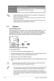
... • If the steps above do not need to clear the RTC when the system hangs due to pins 2-3. F1A55-M LX PLUS CLRTC 12 23 Normal (Default) Clear RTC F1A55-M LX PLUS Clear RTC RAM To erase the RTC RAM: 1. Except when clearing the RTC RAM, never remove the cap on pins...data. Turn OFF the computer and unplug the power cord. 2. See page 1-22 for details. • Connect a chassis fan to the motherboard connector labeled CHA_FAN when using multiple graphics cards for better thermal environment. 1.9 Jumpers Clear RTC RAM (CLRTC) This jumper allows you provide sufficient ...
... • If the steps above do not need to clear the RTC when the system hangs due to pins 2-3. F1A55-M LX PLUS CLRTC 12 23 Normal (Default) Clear RTC F1A55-M LX PLUS Clear RTC RAM To erase the RTC RAM: 1. Except when clearing the RTC RAM, never remove the cap on pins...data. Turn OFF the computer and unplug the power cord. 2. See page 1-22 for details. • Connect a chassis fan to the motherboard connector labeled CHA_FAN when using multiple graphics cards for better thermal environment. 1.9 Jumpers Clear RTC RAM (CLRTC) This jumper allows you provide sufficient ...
User Manual
Page 33
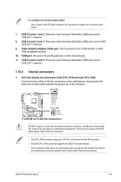
...PWR GND F1A55-M LX PLUS CHA_FAN GND +12V Rotation F1A55-M LX PLUS fan connectors DO NOT forget to connect the fan cables to support an 8-channel audio output. 7. USB 2.0 ports 3 and 4. USB 2.0 ports 5 and 6. Insufficient air flow inside the system may damage the motherboard components. ASUS F1A55-M LX Series 1-...24 W) fan power. • Only the CPU_FAN connector supports the ASUS Fan Xpert feature. • If you install two VGA cards, we recommend that you plug the rear chassis fan cable to the motherboard connector labeled CHA_FAN for USB 2.0/1.1 devices. 8. To configure an 8-...
...PWR GND F1A55-M LX PLUS CHA_FAN GND +12V Rotation F1A55-M LX PLUS fan connectors DO NOT forget to connect the fan cables to support an 8-channel audio output. 7. USB 2.0 ports 3 and 4. USB 2.0 ports 5 and 6. Insufficient air flow inside the system may damage the motherboard components. ASUS F1A55-M LX Series 1-...24 W) fan power. • Only the CPU_FAN connector supports the ASUS Fan Xpert feature. • If you install two VGA cards, we recommend that you plug the rear chassis fan cable to the motherboard connector labeled CHA_FAN for USB 2.0/1.1 devices. 8. To configure an 8-...
User Manual
Page 37
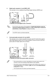
See section 2.5.5 Onboard Devices Configuration for an additional Sony/Philips Digital Interface (S/PDIF) port. +5V SPDIFOUT GND F1A55-M LX PLUS SPDIF_OUT F1A55-M LX PLUS Digital audio connector Ensure that the audio device of the motherboard high-definition audio capability. • If you connect a high-definition front panel audio module to this connector to avail of Sound playback is... for a chassis-mounted front panel audio I /O module cable to [HD]. Go to Start > Control Panel > Sounds and Audio Devices > Sound Playback to configure the setting. ASUS F1A55-M LX Series 1-25
See section 2.5.5 Onboard Devices Configuration for an additional Sony/Philips Digital Interface (S/PDIF) port. +5V SPDIFOUT GND F1A55-M LX PLUS SPDIF_OUT F1A55-M LX PLUS Digital audio connector Ensure that the audio device of the motherboard high-definition audio capability. • If you connect a high-definition front panel audio module to this connector to avail of Sound playback is... for a chassis-mounted front panel audio I /O module cable to [HD]. Go to Start > Control Panel > Sounds and Audio Devices > Sound Playback to configure the setting. ASUS F1A55-M LX Series 1-25
User Manual
Page 38
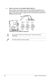
Doing so will damage the motherboard! USB1112 USB910 USB78 USB+5V USB_P12USB_P12+ GND NC USB+5V USB_P10USB_P10+ GND NC USB+5V USB_P8USB_P8+ GND NC F1A55-M LX PLUS PIN 1 PIN 1 PIN 1 USB+5V USB_P11USB_P11+ GND USB+5V USB_P9USB_P9+ GND USB+5V USB_P7USB_P7+ GND F1A55-M LX PLUS USB2.0 connectors Never connect a 1394 cable to a slot opening at the back of...
Doing so will damage the motherboard! USB1112 USB910 USB78 USB+5V USB_P12USB_P12+ GND NC USB+5V USB_P10USB_P10+ GND NC USB+5V USB_P8USB_P8+ GND NC F1A55-M LX PLUS PIN 1 PIN 1 PIN 1 USB+5V USB_P11USB_P11+ GND USB+5V USB_P9USB_P9+ GND USB+5V USB_P7USB_P7+ GND F1A55-M LX PLUS USB2.0 connectors Never connect a 1394 cable to a slot opening at the back of...
User Manual
Page 43
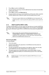
...boot failure! The utility automatically checks the devices for F1A55-M LX PLUS). • The BIOS file in the removable device into F1A55MLX.ROM(for F1A55-M LX) or F1A55MLP.ROM(for the BIOS file. When found, the utility reads the BIOS file and enters ASUS EZ Flash 2 utility automatically. 4. DO NOT ... at www.asus.com. Insert the support DVD to the USB port. 3. Press to switch to the Folder Info field. 6. 3. Press to switch to the Drive field. 4. Recovering the BIOS To recover the BIOS: 1. Doing so can restore a corrupted BIOS file using the motherboard support DVD or...
...boot failure! The utility automatically checks the devices for F1A55-M LX PLUS). • The BIOS file in the removable device into F1A55MLX.ROM(for F1A55-M LX) or F1A55MLP.ROM(for the BIOS file. When found, the utility reads the BIOS file and enters ASUS EZ Flash 2 utility automatically. 4. DO NOT ... at www.asus.com. Insert the support DVD to the USB port. 3. Press to switch to the Folder Info field. 6. 3. Press to switch to the Drive field. 4. Recovering the BIOS To recover the BIOS: 1. Doing so can restore a corrupted BIOS file using the motherboard support DVD or...
User Manual
Page 48
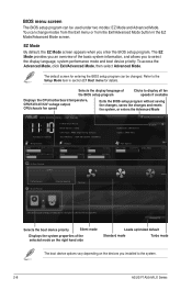
... 2.7 Boot menu for entering the BIOS setup program can be changed. EZ Mode Tuesday [1/1/2008] F1A55-M LX PLUS BIOS Version : 0202 CPU Type : AMD Engineering Sample Total Memory : 1024 MB (DDR3 1333MHz)... appears when you installed to display all fan speeds if available Displays the CPU/motherboard temperature, CPU/5V/3.3V/12V voltage output, CPU/chassis fan speed Exits the BIOS... Mode provides you an overview of the BIOS setup program Clicks to the system. 2-8 ASUS F1A55-M LX Series The default screen for details. Selects the display language of the basic system information,...
... 2.7 Boot menu for entering the BIOS setup program can be changed. EZ Mode Tuesday [1/1/2008] F1A55-M LX PLUS BIOS Version : 0202 CPU Type : AMD Engineering Sample Total Memory : 1024 MB (DDR3 1333MHz)... appears when you installed to display all fan speeds if available Displays the CPU/motherboard temperature, CPU/5V/3.3V/12V voltage output, CPU/chassis fan speed Exits the BIOS... Mode provides you an overview of the BIOS setup program Clicks to the system. 2-8 ASUS F1A55-M LX Series The default screen for details. Selects the display language of the basic system information,...

User Manual
Page 70
Country: TAIWAN Authorized representative in Europe: ASUS COMPUTER GmbH Address, City: HARKORT STR. 21-23, 40880 RATINGEN Country: GERMANY declare the following apparatus: Product name : Motherboard Model name : F1A55-M LX, F1A55-M LX PLUS conform with part 15 of the FCC Rules. Phone/Fax No: (510)739-3777/(510)608-4555 hereby declares that may cause undesired operation. DECLARATION...
Country: TAIWAN Authorized representative in Europe: ASUS COMPUTER GmbH Address, City: HARKORT STR. 21-23, 40880 RATINGEN Country: GERMANY declare the following apparatus: Product name : Motherboard Model name : F1A55-M LX, F1A55-M LX PLUS conform with part 15 of the FCC Rules. Phone/Fax No: (510)739-3777/(510)608-4555 hereby declares that may cause undesired operation. DECLARATION...


