
User Manual
Page 2
... http://support.asus.com/download; Products and corporate names appearing in this manual, including the products and software described in it, may obtain the complete corresponding source code (as defined in the GPL) for which you want to anyone in this product is distributed without the express written permission of the LGPL Software (with the complete machinereadable "work that...
... http://support.asus.com/download; Products and corporate names appearing in this manual, including the products and software described in it, may obtain the complete corresponding source code (as defined in the GPL) for which you want to anyone in this product is distributed without the express written permission of the LGPL Software (with the complete machinereadable "work that...
User Manual
Page 4
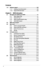
... 2.1.1 ASUS Update utility 2-1 2.1.2 ASUS EZ Flash 2 2-2 2.1.3 ASUS CrashFree BIOS 3 utility 2-3 2.1.4 ASUS BIOS Updater 2-4 2.2 BIOS setup program 2-7 2.3 Main menu 2-11 2.3.1 System Language [English 2-11 2.3.2 System Date [Day xx/xx/xxxx 2-11 2.3.3 System Time [xx:xx:xx 2-11 2.3.4 Security 2-11 2.4 Ai Tweaker menu 2-13 2.4.1 Ai Overclock Tuner [Auto 2-14 2.4.2 Memory Frequency [Auto 2-14 2.4.3 APU Multiplier [Auto 2-14 2.4.4 EPU Power Saving Mode [Disabled 2-14 2.4.5 OC Tuner 2-14 2.4.6 DRAM Timing Control 2-15 2.4.7 CPU Offset Mode Sign 2-15 2.4.8 DRAM Voltage [Auto 2-15...
... 2.1.1 ASUS Update utility 2-1 2.1.2 ASUS EZ Flash 2 2-2 2.1.3 ASUS CrashFree BIOS 3 utility 2-3 2.1.4 ASUS BIOS Updater 2-4 2.2 BIOS setup program 2-7 2.3 Main menu 2-11 2.3.1 System Language [English 2-11 2.3.2 System Date [Day xx/xx/xxxx 2-11 2.3.3 System Time [xx:xx:xx 2-11 2.3.4 Security 2-11 2.4 Ai Tweaker menu 2-13 2.4.1 Ai Overclock Tuner [Auto 2-14 2.4.2 Memory Frequency [Auto 2-14 2.4.3 APU Multiplier [Auto 2-14 2.4.4 EPU Power Saving Mode [Disabled 2-14 2.4.5 OC Tuner 2-14 2.4.6 DRAM Timing Control 2-15 2.4.7 CPU Offset Mode Sign 2-15 2.4.8 DRAM Voltage [Auto 2-15...
User Manual
Page 9
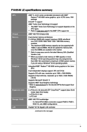
... D-Sub Supports DVI with ATI® CrossFireX™ support (blue @x16 mode, black @x4 mode) 1 x PCIe 2.0 x1 slot 1 x PCI slot AMD® A55 FCH southbridge: - 6 x Serial ATA 3.0Gb/s connectors support RAID 0, RAID 1, RAID 10, and JBOD configurations Realtek® 8111E Gigabit LAN controller (continued on the APU types. ** Refer to 1920 x 1200 @60Hz Supports D-Sub with 16GB or above DIMMs. ASUS will update the memory QVL once the DIMMs are using a Windows® 32-bit operating...
... D-Sub Supports DVI with ATI® CrossFireX™ support (blue @x16 mode, black @x4 mode) 1 x PCIe 2.0 x1 slot 1 x PCI slot AMD® A55 FCH southbridge: - 6 x Serial ATA 3.0Gb/s connectors support RAID 0, RAID 1, RAID 10, and JBOD configurations Realtek® 8111E Gigabit LAN controller (continued on the APU types. ** Refer to 1920 x 1200 @60Hz Supports D-Sub with 16GB or above DIMMs. ASUS will update the memory QVL once the DIMMs are using a Windows® 32-bit operating...
User Manual
Page 11
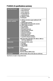
... DVD Form factor 3 x USB 2.0 connectors support additional 6 USB 2.0 ports 1 x S/PDIF output connector 1 x High-definition front panel audio connector 6 x SATA 3.0Gb/s connectors 1 x LPT connector 1 x COM connector 1 x Front panel connector 1 x Internal speaker connector 1 x CPU fan connector 1 x Chassis fan connector 1 x Power fan connector 1 x 24-pin EATX power connector 1 x 4-pin ATX 12V power connector 32Mb Flash ROM, UEFI BIOS, PnP, DMI 2.0, WfM 2.0, ACPI 2.0a, SM BIOS 2.6 2 x Serial ATA 3.0Gb/s cables 1 x I/O shield 1 x User Manual 1 x Support DVD Drivers ASUS PC Probe II ASUS Update...
... DVD Form factor 3 x USB 2.0 connectors support additional 6 USB 2.0 ports 1 x S/PDIF output connector 1 x High-definition front panel audio connector 6 x SATA 3.0Gb/s connectors 1 x LPT connector 1 x COM connector 1 x Front panel connector 1 x Internal speaker connector 1 x CPU fan connector 1 x Chassis fan connector 1 x Power fan connector 1 x 24-pin EATX power connector 1 x 4-pin ATX 12V power connector 32Mb Flash ROM, UEFI BIOS, PnP, DMI 2.0, WfM 2.0, ACPI 2.0a, SM BIOS 2.6 2 x Serial ATA 3.0Gb/s cables 1 x I/O shield 1 x User Manual 1 x Support DVD Drivers ASUS PC Probe II ASUS Update...
User Manual
Page 14
... new ASUS UEFI BIOS is an Unified Extensible Firmware Interface that offers a user-friendly interface that supports iPod, iPhone, and iPad. • Check your USB device's conditions. This easy OC tool allows you to get high quality images. AMD® A55 (Hudson D2) FCH Chipset AMD® A55 FCH (Hudson D2) is designed to support up to 5GT/s interface and PCI Express 2.0 x 16 (at x4 speed) graphics...
... new ASUS UEFI BIOS is an Unified Extensible Firmware Interface that offers a user-friendly interface that supports iPod, iPhone, and iPad. • Check your USB device's conditions. This easy OC tool allows you to get high quality images. AMD® A55 (Hudson D2) FCH Chipset AMD® A55 FCH (Hudson D2) is designed to support up to 5GT/s interface and PCI Express 2.0 x 16 (at x4 speed) graphics...
User Manual
Page 15
... The motherboard is in variety of useful profiles offer flexible controls of the product and thus mitigate environmental impacts. ASUS CrashFree BIOS 3 ASUS CrashFree BIOS 3 is a user-friendly utility that contains the BIOS file. ASUS F1A55-M LE 1-3 Fan Xpert ASUS Fan Xpert intelligently allows you to different ambient temperatures caused by power surges from switching power supply unit (PSU). It allows you to adjust the CPU fan speed according to supervise overclocking, energy management, fan speed control, and voltage...
... The motherboard is in variety of useful profiles offer flexible controls of the product and thus mitigate environmental impacts. ASUS CrashFree BIOS 3 ASUS CrashFree BIOS 3 is a user-friendly utility that contains the BIOS file. ASUS F1A55-M LE 1-3 Fan Xpert ASUS Fan Xpert intelligently allows you to different ambient temperatures caused by power surges from switching power supply unit (PSU). It allows you to adjust the CPU fan speed according to supervise overclocking, energy management, fan speed control, and voltage...
User Manual
Page 25
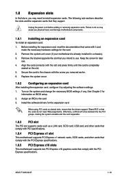
... seated on BIOS setup. 2. Secure the card to the card. 3. Assign an IRQ to the chassis with it by adjusting the software settings. 1. ASUS F1A55-M LE 1-13 Before installing the expansion card, read the documentation that came with the screw you intend to install expansion cards. Unplug the power cord before adding or removing expansion cards. Align the card connector with the PCI Express specifications. Turn on shared slots, ensure that the drivers support "Share...
... seated on BIOS setup. 2. Secure the card to the card. 3. Assign an IRQ to the chassis with it by adjusting the software settings. 1. ASUS F1A55-M LE 1-13 Before installing the expansion card, read the documentation that came with the screw you intend to install expansion cards. Unplug the power cord before adding or removing expansion cards. Align the card connector with the PCI Express specifications. Turn on shared slots, ensure that the drivers support "Share...
User Manual
Page 26
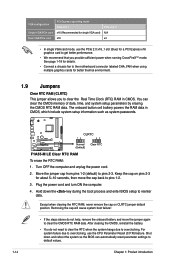
...; Connect a chassis fan to the motherboard connector labeled CHA_FAN when using multiple graphics cards for better thermal environment. 1.9 Jumpers Clear RTC RAM (CLRTC) This jumper allows you provide sufficient power when running CrossFireX™ mode. Keep the cap on CLRTC jumper default position. Shut down the key during the boot process and enter BIOS setup to overclocking. For system failure due to default values. 1-14 Chapter 1: Product introduction You can automatically reset parameter settings to overclocking, use the PCIe...
...; Connect a chassis fan to the motherboard connector labeled CHA_FAN when using multiple graphics cards for better thermal environment. 1.9 Jumpers Clear RTC RAM (CLRTC) This jumper allows you provide sufficient power when running CrossFireX™ mode. Keep the cap on CLRTC jumper default position. Shut down the key during the boot process and enter BIOS setup to overclocking. For system failure due to default values. 1-14 Chapter 1: Product introduction You can automatically reset parameter settings to overclocking, use the PCIe...
User Manual
Page 28
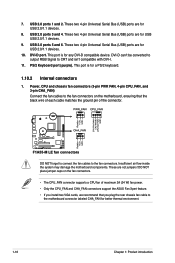
... USB USB 2.0/1.1 devices. 9. These two 4-pin Universal Serial Bus (USB) ports are not jumpers! These are for better thermal environment. 1-16 Chapter 1: Product introduction DO NOT place jumper caps on the motherboard, ensuring that you plug the rear chassis fan cable to the fan connectors on the fan connectors. • The CPU_FAN connector supports a CPU fan of maximum 2A (24 W) fan power. • Only the CPU_FAN and CHA_FAN connectors support the ASUS Fan Xpert feature. • If you install two VGA cards...
... USB USB 2.0/1.1 devices. 9. These two 4-pin Universal Serial Bus (USB) ports are not jumpers! These are for better thermal environment. 1-16 Chapter 1: Product introduction DO NOT place jumper caps on the motherboard, ensuring that you plug the rear chassis fan cable to the fan connectors on the fan connectors. • The CPU_FAN connector supports a CPU fan of maximum 2A (24 W) fan power. • Only the CPU_FAN and CHA_FAN connectors support the ASUS Fan Xpert feature. • If you install two VGA cards...
User Manual
Page 30
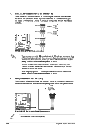
... create a RAID 0, RAID 1, RAID 10, or JBOD configuration through the onboard controller. • These connectors are for the Serial ATA 3.0 Gb/s signal cables for a serial (COM) port. 4. Serial ATA 3.0 Gb/s connectors (7-pin SATA3G 1~6) These connectors are set the type of the system chassis. In IDE mode, you are using Windows® XP SP3 or later version. • When using these connectors. See section 2.5.2 SATA Configuration for details. 5. Connect the serial port module cable to this connector, then install the module to a slot opening at...
... create a RAID 0, RAID 1, RAID 10, or JBOD configuration through the onboard controller. • These connectors are for the Serial ATA 3.0 Gb/s signal cables for a serial (COM) port. 4. Serial ATA 3.0 Gb/s connectors (7-pin SATA3G 1~6) These connectors are set the type of the system chassis. In IDE mode, you are using Windows® XP SP3 or later version. • When using these connectors. See section 2.5.2 SATA Configuration for details. 5. Connect the serial port module cable to this connector, then install the module to a slot opening at...

User Manual
Page 34
.... Click Drivers, Utilities, Make Disk, Manual, and Contact tabs to avail all motherboard features. To run the DVD. 1-22 Chapter 1: Product introduction The following screen is NOT enabled on your hardware. • Motherboard settings and hardware options vary. Click an icon to display Support DVD/ motherboard information Click an item to locate the file ASSETUP.EXE from the BIN folder. Always install the latest OS version and corresponding updates to...
.... Click Drivers, Utilities, Make Disk, Manual, and Contact tabs to avail all motherboard features. To run the DVD. 1-22 Chapter 1: Product introduction The following screen is NOT enabled on your hardware. • Motherboard settings and hardware options vary. Click an icon to display Support DVD/ motherboard information Click an item to locate the file ASSETUP.EXE from the BIN folder. Always install the latest OS version and corresponding updates to...
User Manual
Page 35
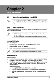
... original motherboard BIOS file to a USB flash disk in the support DVD that comes with the motherboard package. From the list, select either through a network or an Internet Service Provider (ISP). • This utility is a utility that you update the BIOS using the ASUS Update utility. 2.1.1 ASUS Update utility The ASUS Update is available in case you need to avoid network traffic, then click Next. Quit all Windows® applications before you wish to complete the installation. The ASUS Update main screen appears...
... original motherboard BIOS file to a USB flash disk in the support DVD that comes with the motherboard package. From the list, select either through a network or an Internet Service Provider (ISP). • This utility is a utility that you update the BIOS using the ASUS Update utility. 2.1.1 ASUS Update utility The ASUS Update is available in case you need to avoid network traffic, then click Next. Quit all Windows® applications before you wish to complete the installation. The ASUS Update main screen appears...

User Manual
Page 37
... BIOS To recover the BIOS: 1. To ensure system compatibility and stability, we recommend that you to enter BIOS Setup to recover BIOS setting. You can cause system boot failure! The utility automatically checks the devices for the BIOS file. Press to switch to find the BIOS file, and then press to the USB port. 3. Download the latest BIOS file from the ASUS website at www.asus.com. Insert the support DVD to the optical drive or the USB flash drive...
... BIOS To recover the BIOS: 1. To ensure system compatibility and stability, we recommend that you to enter BIOS Setup to recover BIOS setting. You can cause system boot failure! The utility automatically checks the devices for the BIOS file. Press to switch to find the BIOS file, and then press to the USB port. 3. Download the latest BIOS file from the ASUS website at www.asus.com. Insert the support DVD to the optical drive or the USB flash drive...
User Manual
Page 38
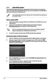
... BIOS Updater to a hard disk drive or USB flash drive in DOS environment. Prepare the motherboard support DVD and a USB flash drive in DOS environment 1. Download the latest BIOS file and BIOS Updater from Drive C (optical drive) to show the BIOS Boot Device Select Menu. NTFS is not supported under DOS environment. Do not save them on the USB flash drive. Turn off the computer and disconnect all SATA hard disk drives (optional). C:\>d: D:\> 2-4 ASUS F1A55-M LE This utility also allows you to copy the current BIOS file that you to boot using defaults...
... BIOS Updater to a hard disk drive or USB flash drive in DOS environment. Prepare the motherboard support DVD and a USB flash drive in DOS environment 1. Download the latest BIOS file and BIOS Updater from Drive C (optical drive) to show the BIOS Boot Device Select Menu. NTFS is not supported under DOS environment. Do not save them on the USB flash drive. Turn off the computer and disconnect all SATA hard disk drives (optional). C:\>d: D:\> 2-4 ASUS F1A55-M LE This utility also allows you to copy the current BIOS file that you to boot using defaults...
User Manual
Page 48
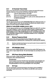
...] [DDR3-1600MHz] [DDR3-1866MHz] Selecting a very high memory frequency may cause the system to set the multiplier between the CPU Core Clock and the FSB Frequency. Configuration options: [Disabled] [Enabled] EPU Setting [Auto] This item appears only when The EPU Power Saving Mode is set the Ai Overclock Tuner item to start automatic overclocking. 2-14 ASUS F1A55-M LE You can also key in the desired value using the numeric keypad. Press and select OK...
...] [DDR3-1600MHz] [DDR3-1866MHz] Selecting a very high memory frequency may cause the system to set the multiplier between the CPU Core Clock and the FSB Frequency. Configuration options: [Disabled] [Enabled] EPU Setting [Auto] This item appears only when The EPU Power Saving Mode is set the Ai Overclock Tuner item to start automatic overclocking. 2-14 ASUS F1A55-M LE You can also key in the desired value using the numeric keypad. Press and select OK...

User Manual
Page 51
Advanced Mode Exit Main Ai Tweaker > CPU Configuration > SATA Configuration > USB Configuration > NB Configuration > Onboard Devices Configuration > APM Advanced Monitor Boot Tool CPU Configuration Parameters →←: Select Screen ↑↓: Select Item Enter: Select +/-: Change Opt. The items shown in this function. Configuration options: [Auto] [Enabled] [Disabled] CPB Mode [Auto] Disables the CPB (Core Performance Boost) mode or set it to change the settings for the CPU and other system devices. F1: General Help F2: Previous Values F5: Optimized Defaults...
Advanced Mode Exit Main Ai Tweaker > CPU Configuration > SATA Configuration > USB Configuration > NB Configuration > Onboard Devices Configuration > APM Advanced Monitor Boot Tool CPU Configuration Parameters →←: Select Screen ↑↓: Select Item Enter: Select +/-: Change Opt. The items shown in this function. Configuration options: [Auto] [Enabled] [Disabled] CPB Mode [Auto] Disables the CPB (Core Performance Boost) mode or set it to change the settings for the CPU and other system devices. F1: General Help F2: Previous Values F5: Optimized Defaults...
User Manual
Page 52
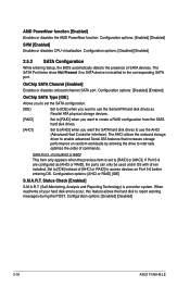
... the hard disk to access devices on random workloads by allowing the drive to use the Serial ATA hard disk drives as [AHCI or RAID], the ports can only be used under OS with driver installed. Configuration options: [Enabled] [Disabled] 2-18 ASUS F1A55-M LE The SATA Port items show Not Present if no SATA device is a monitor system. OnChip SATA Channel [Enabled] Enables or disables onboard channel SATA port. Configuration options: [Enabled] [Disabled] SVM [Enabled] Enables or disables CPU virtualization. Configuration options: [Disabled] [Enabled] OnChip SATA Type [IDE] Allows...
... the hard disk to access devices on random workloads by allowing the drive to use the Serial ATA hard disk drives as [AHCI or RAID], the ports can only be used under OS with driver installed. Configuration options: [Enabled] [Disabled] 2-18 ASUS F1A55-M LE The SATA Port items show Not Present if no SATA device is a monitor system. OnChip SATA Channel [Enabled] Enables or disables onboard channel SATA port. Configuration options: [Enabled] [Disabled] SVM [Enabled] Enables or disables CPU virtualization. Configuration options: [Disabled] [Enabled] OnChip SATA Type [IDE] Allows...
User Manual
Page 53
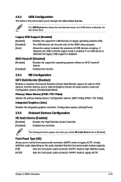
...None. Configuration options: [IGFX Video] [PCIE / PCI Video] Integrated Graphics [Auto] Enables the integrated graphics controller. Front Panel Type [HD] Allows you set the front panel audio connector (AAFP) mode to legacy AC'97 or highdefinition audio depending on VGA devices. EHCI Hand-off [Disabled] [Enabled] Enables the support for operating systems without an EHCI hand‑off feature. [Disabled] Disables the function. 2.5.4 NB Configuration IGFX Multi-Monitor [Disabled] Enables or disables the Internal Graphics Device Multi-Monitor support for the BIOS setup program. [Auto...
...None. Configuration options: [IGFX Video] [PCIE / PCI Video] Integrated Graphics [Auto] Enables the integrated graphics controller. Front Panel Type [HD] Allows you set the front panel audio connector (AAFP) mode to legacy AC'97 or highdefinition audio depending on VGA devices. EHCI Hand-off [Disabled] [Enabled] Enables the support for operating systems without an EHCI hand‑off feature. [Disabled] Disables the function. 2.5.4 NB Configuration IGFX Multi-Monitor [Disabled] Enables or disables the Internal Graphics Device Multi-Monitor support for the BIOS setup program. [Auto...
User Manual
Page 54
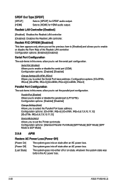
... before the AC power loss. 2-20 ASUS F1A55-M LE IRQ=5,6,7,9,10,11,12] Device Mode [Auto] Allows you to set the Printer port mode. Configuration options: [Enabled] [Disabled] Serial Port Configuration The sub-items in this menu allow you to enable or disable the parallel port (LPT/LPTE). Parallel Port [Enabled] Allows you to select the Parallel Port base address. IRQ=5] [IO=378h; Realtek LAN Controller [Enabled] [Enabled] Enables the Realtek LAN controller. [Disabled] Disables the Realtek LAN controller. Realtek PXE OPROM [Disabled] This item...
... before the AC power loss. 2-20 ASUS F1A55-M LE IRQ=5,6,7,9,10,11,12] Device Mode [Auto] Allows you to set the Printer port mode. Configuration options: [Enabled] [Disabled] Serial Port Configuration The sub-items in this menu allow you to enable or disable the parallel port (LPT/LPTE). Parallel Port [Enabled] Allows you to select the Parallel Port base address. IRQ=5] [IO=378h; Realtek LAN Controller [Enabled] [Enabled] Enables the Realtek LAN controller. [Disabled] Disables the Realtek LAN controller. Realtek PXE OPROM [Disabled] This item...
User Manual
Page 56
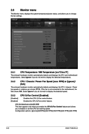
... only when you enable the CPU Q-Fan Control feature and allows you to disable or set the CPU fan warning speed. Advanced Mode Exit Main Ai Tweaker Advanced Monitor CPU Temperature +45ºC / +113ºF MB Temperature +34ºC / +93ºF CPU Fan Speed 4515 RPM Chassis Fan Speed N/A Power Fan Speed N/A CPU Q-Fan Control Enabled CPU Fan Speed Low Limit 600 RPM CPU Fan Profile Standard CPU Voltage +1.384 V 3.3V Voltage +3.280 V 5V Voltage +5.126 V 12V Voltage +12.000 V Anti Surge Support Enabled Boot CPU Temperature Tool →←...
... only when you enable the CPU Q-Fan Control feature and allows you to disable or set the CPU fan warning speed. Advanced Mode Exit Main Ai Tweaker Advanced Monitor CPU Temperature +45ºC / +113ºF MB Temperature +34ºC / +93ºF CPU Fan Speed 4515 RPM Chassis Fan Speed N/A Power Fan Speed N/A CPU Q-Fan Control Enabled CPU Fan Speed Low Limit 600 RPM CPU Fan Profile Standard CPU Voltage +1.384 V 3.3V Voltage +3.280 V 5V Voltage +5.126 V 12V Voltage +12.000 V Anti Surge Support Enabled Boot CPU Temperature Tool →←...


