

User Guide
Page 15
1.2 Serial number label Before requesting support from the ASUS Technical Support team, you must take note of the product, ASUS Technical Support team members can then offer a quicker and satisfying solution to your problems. ESC4000 G3 xxS0xxxxxxxxxx 21 ESC4000 G3S xxS0xxxxxxxxxx 2 1 The serial number on ESC4000 G3/G3S is printed on the Asset tag. ASUS ESC4000 G3/G3S Series 1-3 With the correct serial number of the product's serial number containing 14 characters such as xxS0xxxxxxxxxx. See the figure below.
1.2 Serial number label Before requesting support from the ASUS Technical Support team, you must take note of the product, ASUS Technical Support team members can then offer a quicker and satisfying solution to your problems. ESC4000 G3 xxS0xxxxxxxxxx 21 ESC4000 G3S xxS0xxxxxxxxxx 2 1 The serial number on ESC4000 G3/G3S is printed on the Asset tag. ASUS ESC4000 G3/G3S Series 1-3 With the correct serial number of the product's serial number containing 14 characters such as xxS0xxxxxxxxxx. See the figure below.

User Guide
Page 16
...ASUS ESC4000 G3/G3S Series servers features the ASUS Z10PG-D16 Series server board that supports Intel® LGA 2011-3 Xeon® processor from the E5-2600 V3 product family. Support software RAID 0, 1, 10 & 5) LSI MegaRAID driver supports software RAID 0, 1& 10 (Windows & Linux) Optional kits: ASUS PIKE II 3008 8-port SAS 12G RAID card ASUS... Bus Core Logic Memory Total Slots Capacity Memory Type Memory Size Total PCI/PCI-X/ PCI-E Slots Expansion Slots Slot Type ESC4000 G3 ESC4000 G3S 2 x Socket R3 (LGA 2011-3) Intel® Xeon® processor E5-2600 v3 product family QPI 6.4 / ...
...ASUS ESC4000 G3/G3S Series servers features the ASUS Z10PG-D16 Series server board that supports Intel® LGA 2011-3 Xeon® processor from the E5-2600 V3 product family. Support software RAID 0, 1, 10 & 5) LSI MegaRAID driver supports software RAID 0, 1& 10 (Windows & Linux) Optional kits: ASUS PIKE II 3008 8-port SAS 12G RAID card ASUS... Bus Core Logic Memory Total Slots Capacity Memory Type Memory Size Total PCI/PCI-X/ PCI-E Slots Expansion Slots Slot Type ESC4000 G3 ESC4000 G3S 2 x Socket R3 (LGA 2011-3) Intel® Xeon® processor E5-2600 v3 product family QPI 6.4 / ...

User Guide
Page 17
System specifications Model Name ESC4000 G3 HDD Bays I /O 3 x RJ-45 ports (One for ASMB8-iKVM) 4 x USB ports (2 x Front USB 2.0 , 2 x Rear USB 3.0) 1 x VGA Port ... x 87 mm (2U) Net Weight Kg (CPU, DRAM & HDD not included) 19 Kg * Subject to change without any notice. ** Refer to www.asus.com for North America) ESC4000 G3S 6 x Hot-swap 2.5-inch HDD Bays - Rear I = Internal A or S will be hot-swappable 8 x Hot-swap 3.5-inch HDD Bays Networking LAN ...) No Device / DVD-RW (DVD-RW default for the latest OS AVL update. (continued on the next page) ASUS ESC4000 G3/G3S Series 1-5
System specifications Model Name ESC4000 G3 HDD Bays I /O 3 x RJ-45 ports (One for ASMB8-iKVM) 4 x USB ports (2 x Front USB 2.0 , 2 x Rear USB 3.0) 1 x VGA Port ... x 87 mm (2U) Net Weight Kg (CPU, DRAM & HDD not included) 19 Kg * Subject to change without any notice. ** Refer to www.asus.com for North America) ESC4000 G3S 6 x Hot-swap 2.5-inch HDD Bays - Rear I = Internal A or S will be hot-swappable 8 x Hot-swap 3.5-inch HDD Bays Networking LAN ...) No Device / DVD-RW (DVD-RW default for the latest OS AVL update. (continued on the next page) ASUS ESC4000 G3/G3S Series 1-5
User Guide
Page 19
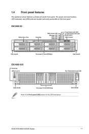
... tag HDD Access LED Message LED LAN1 LED LAN2 LED 21 Power button with LED Location button with LED Reset button USB 2.0 ports Steel handle ESC4000 G3S Asset tag USB 2.0 ports Hot-swap 3.5-inch HDD Bays Steel handle Fron Panel buttons and LED 2 1 Steel handle Hot-swap 2.5-inch HDD Bays Refer to... for the LED descriptions. The power and reset buttons, LED indicators, and USB ports are located and easily accessible on the front panel. Steel handle ASUS ESC4000 G3/G3S Series 1-7 1.4 Front panel features The barebone server features a simple yet stylish front panel.
... tag HDD Access LED Message LED LAN1 LED LAN2 LED 21 Power button with LED Location button with LED Reset button USB 2.0 ports Steel handle ESC4000 G3S Asset tag USB 2.0 ports Hot-swap 3.5-inch HDD Bays Steel handle Fron Panel buttons and LED 2 1 Steel handle Hot-swap 2.5-inch HDD Bays Refer to... for the LED descriptions. The power and reset buttons, LED indicators, and USB ports are located and easily accessible on the front panel. Steel handle ASUS ESC4000 G3/G3S Series 1-7 1.4 Front panel features The barebone server features a simple yet stylish front panel.
User Guide
Page 21
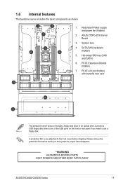
... the USB ports on the system for proper heat dissipation. *WARNING HAZARDOUS MOVING PARTS KEEP FINGERS AND OTHER BODY PARTS AWAY ASUS ESC4000 G3/G3S Series 1-9 Redundant Power supply and power fan (hidden) 2. ASUS Z10PG-D16 Server Board 3. SATA/SAS backplane (hidden) 5. 1.6 Internal features The barebone server includes the basic components as shown. 1. PCI-E Expansion...
... the USB ports on the system for proper heat dissipation. *WARNING HAZARDOUS MOVING PARTS KEEP FINGERS AND OTHER BODY PARTS AWAY ASUS ESC4000 G3/G3S Series 1-9 Redundant Power supply and power fan (hidden) 2. ASUS Z10PG-D16 Server Board 3. SATA/SAS backplane (hidden) 5. 1.6 Internal features The barebone server includes the basic components as shown. 1. PCI-E Expansion...

User Guide
Page 23
... pressed (Press the location switch again to turn off) OFF No LAN connection Blinking LAN is transmitting or receiving data ON LAN connection is normal; ESC4000 G3S Power button with LED Message LED HDD Access LED 2 1 Location button with LED LAN2 LED LAN1 LED 2 1 LED Icon Display status Description Power button with... LED Location button with LED LAN LEDs ON System power ON OFF No activity Blinking Read/write data into the HDD OFF System is present ASUS ESC4000 G3/G3S Series 1-11
... pressed (Press the location switch again to turn off) OFF No LAN connection Blinking LAN is transmitting or receiving data ON LAN connection is normal; ESC4000 G3S Power button with LED Message LED HDD Access LED 2 1 Location button with LED LAN2 LED LAN1 LED 2 1 LED Icon Display status Description Power button with... LED Location button with LED LAN LEDs ON System power ON OFF No activity Blinking Read/write data into the HDD OFF System is present ASUS ESC4000 G3/G3S Series 1-11

User Guide
Page 25
1.7.3 HDD status LEDs ESC4000 G3 HDD status LED 21 HDD LED Green Red Description The installed HDD is in good condition HDD locate or HDD failure ESC4000 G3S HDD status LED 2 1 2 1 HDD LED Green Red Description The installed HDD is in good condition HDD locate or HDD failure ASUS ESC4000 G3/G3S Series 1-13
1.7.3 HDD status LEDs ESC4000 G3 HDD status LED 21 HDD LED Green Red Description The installed HDD is in good condition HDD locate or HDD failure ESC4000 G3S HDD status LED 2 1 2 1 HDD LED Green Red Description The installed HDD is in good condition HDD locate or HDD failure ASUS ESC4000 G3/G3S Series 1-13

User Guide
Page 31
Lift the air duct to the chassis ensuring that the screw holes on the air duct match the screw holes on chassis. 2. Align and replace the air duct to remove it from the chassis. 2.1.1 Air duct To remove the air duct: 1. Secure the air duct to the chassis with three screws. ASUS ESC4000 G3/G3S Series 2-3 To reinstall the air duct: 1. Remove the three screws as shown. 2.
Lift the air duct to the chassis ensuring that the screw holes on the air duct match the screw holes on chassis. 2. Align and replace the air duct to remove it from the chassis. 2.1.1 Air duct To remove the air duct: 1. Secure the air duct to the chassis with three screws. ASUS ESC4000 G3/G3S Series 2-3 To reinstall the air duct: 1. Remove the three screws as shown. 2.

User Guide
Page 33
Load lever ASUS ESC4000 G3/G3S Series 2-5 Press down the load lever with your thumb (A), move it is facing toward you are installing a CPU. To prevent damage to the right until it to the socket pins, do not remove the PnP cap unless you and the triangle mark is on the top-right position. 3. Align the system such that the socket box is released from the retention tab (B), then gently lift the load lever (C). 2.
Load lever ASUS ESC4000 G3/G3S Series 2-5 Press down the load lever with your thumb (A), move it is facing toward you are installing a CPU. To prevent damage to the right until it to the socket pins, do not remove the PnP cap unless you and the triangle mark is on the top-right position. 3. Align the system such that the socket box is released from the retention tab (B), then gently lift the load lever (C). 2.

User Guide
Page 35
... (J) then insert the right load lever under the retention tab (K). Keep the PnP cap. 10. PnP cap ASUS ESC4000 G3/G3S Series 2-7 The PnP cap pops out of the load plate is inserted into the retention tab. ASUS will process Return Merchandise Authorization (RMA) requests only if the motherboard comes with the PnP cap on...
... (J) then insert the right load lever under the retention tab (K). Keep the PnP cap. 10. PnP cap ASUS ESC4000 G3/G3S Series 2-7 The PnP cap pops out of the load plate is inserted into the retention tab. ASUS will process Return Merchandise Authorization (RMA) requests only if the motherboard comes with the PnP cap on...

User Guide
Page 37
... heatsink and CPU. Tighten each of the screws with a Phillips screwdriver just enough to attach the heatsink to avoid damaging the motherboard, CPU, or heatsink. ASUS ESC4000 G3/G3S Series 2-9 Fasten the screws to just about the proper tightness to the motherboard. 3. 2.2.2 Installing the CPU heatsink To install the CPU heatsink: 1.
... heatsink and CPU. Tighten each of the screws with a Phillips screwdriver just enough to attach the heatsink to avoid damaging the motherboard, CPU, or heatsink. ASUS ESC4000 G3/G3S Series 2-9 Fasten the screws to just about the proper tightness to the motherboard. 3. 2.2.2 Installing the CPU heatsink To install the CPU heatsink: 1.

User Guide
Page 41
... ejects slightly after you pull out the lever. Place the drive tray on the drive tray connects to release the drive tray. ASUS ESC4000 G3/G3S Series 2-13 2.4 Hard disk drives The ESC4000 G3 system supports hot-swap 3.5-inch SATA/SAS hard disk drives. The hard disk drive installed on a flat and stable surface. 4. Installing the...
... ejects slightly after you pull out the lever. Place the drive tray on the drive tray connects to release the drive tray. ASUS ESC4000 G3/G3S Series 2-13 2.4 Hard disk drives The ESC4000 G3 system supports hot-swap 3.5-inch SATA/SAS hard disk drives. The hard disk drive installed on a flat and stable surface. 4. Installing the...

User Guide
Page 43
... the drive tray in a clean and flat surface. Orient and place the Serial ATA (SATA) HDD/ SAS HDD into the tray. drive tray screw hole ASUS ESC4000 G3/G3S Series 2-15 The drive tray metal beam provides horizontal support to partially eject the tray from being bent or deformed. Ensure that the SATA HDD...
... the drive tray in a clean and flat surface. Orient and place the Serial ATA (SATA) HDD/ SAS HDD into the tray. drive tray screw hole ASUS ESC4000 G3/G3S Series 2-15 The drive tray metal beam provides horizontal support to partially eject the tray from being bent or deformed. Ensure that the SATA HDD...

User Guide
Page 45
... low-profile To install PCI-E expansion cards to the chassis. ASUS ESC4000 G3/G3S Series 2-17 Remove the the screw that supports one x16 slot (x8 Gen3 link) for installing PCI-E x16 low profile cards and one x8 slot (x8 Gen3 link) for installing ASUS PCI-E x8 proprietary cards. 2.5 Expansion slots Ensure to do so...
... low-profile To install PCI-E expansion cards to the chassis. ASUS ESC4000 G3/G3S Series 2-17 Remove the the screw that supports one x16 slot (x8 Gen3 link) for installing PCI-E x16 low profile cards and one x8 slot (x8 Gen3 link) for installing ASUS PCI-E x8 proprietary cards. 2.5 Expansion slots Ensure to do so...

User Guide
Page 47
... connectors on the motherboard. Connect Cable #1 and Cable #2 to Cable #1) internal mini-SAS HD connectors internal mini-SAS HD connector external mini-SAS HD connector ASUS ESC4000 G3/G3S Series 2-19 The mini SAS HD cables are installing a PIKE II 3008 series card.
... connectors on the motherboard. Connect Cable #1 and Cable #2 to Cable #1) internal mini-SAS HD connectors internal mini-SAS HD connector external mini-SAS HD connector ASUS ESC4000 G3/G3S Series 2-19 The mini SAS HD cables are installing a PIKE II 3008 series card.

User Guide
Page 49
... change the necessary BIOS settings, if any. See Chapter 5 for ISA or PCI devices. Turn on BIOS setup. 2. Install the software drivers for more information. 3. ASUS ESC4000 G3/G3S Series 2-21 Assign an IRQ to the Standard Interrupt assignments table for the expansion card. Refer to the card. Standard Interrupt assignments IRQ Priority Standard...
... change the necessary BIOS settings, if any. See Chapter 5 for ISA or PCI devices. Turn on BIOS setup. 2. Install the software drivers for more information. 3. ASUS ESC4000 G3/G3S Series 2-21 Assign an IRQ to the Standard Interrupt assignments table for the expansion card. Refer to the card. Standard Interrupt assignments IRQ Priority Standard...

User Guide
Page 51
2.7 SATA/SAS backplane cabling ESC4000 G3 Connects a 8-pin plug from power supply Connects the data cables connected to the motherboard J1: Connects to the power connector of the slim-type optical drive Onboard SGPIO2/3: Connects to the SGPIO2/3 connector to support Intel RSTe, LSI MegaRAID, and PIKE card SAS RAID function. ASUS ESC4000 G3/G3S Series 2-23
2.7 SATA/SAS backplane cabling ESC4000 G3 Connects a 8-pin plug from power supply Connects the data cables connected to the motherboard J1: Connects to the power connector of the slim-type optical drive Onboard SGPIO2/3: Connects to the SGPIO2/3 connector to support Intel RSTe, LSI MegaRAID, and PIKE card SAS RAID function. ASUS ESC4000 G3/G3S Series 2-23

User Guide
Page 53
... system fan cable from the fan connector on the motherboard. 2. Lift the fan then set aside. 4. You may need to uninstall the other system fans. ASUS ESC4000 G3/G3S Series 2-25 Repeat step 1 to 2 to install the optional components into the system.
... system fan cable from the fan connector on the motherboard. 2. Lift the fan then set aside. 4. You may need to uninstall the other system fans. ASUS ESC4000 G3/G3S Series 2-25 Repeat step 1 to 2 to install the optional components into the system.

User Guide
Page 55
To replace a power supply unit (PSU): 1. Replacement PSU ASUS ESC4000 G3/G3S Series 2-27 PSU lever 3. Lift up the PSU lever. 2. Hold the PSU lever, press the PSU latch (A) then carefully pull the PSU out of your hands in place. Align and insert the replacement PSU into the empty PSU bay until it clicks in performing the following steps. 2.8.2 Redundant power supply units We recommend that you use both of the system chassis (B). Prepare the replacement PSU. 4.
To replace a power supply unit (PSU): 1. Replacement PSU ASUS ESC4000 G3/G3S Series 2-27 PSU lever 3. Lift up the PSU lever. 2. Hold the PSU lever, press the PSU latch (A) then carefully pull the PSU out of your hands in place. Align and insert the replacement PSU into the empty PSU bay until it clicks in performing the following steps. 2.8.2 Redundant power supply units We recommend that you use both of the system chassis (B). Prepare the replacement PSU. 4.

User Guide
Page 57
... or later GPU cards, attach a mylar to the GPU air duct first before installing the air duct to the system. 1. mylar GPU air duct mylar ASUS ESC4000 G3/G3S Series 2-29 Locate and loosen the thumbscrew in the accessory box. The mylar is bundled with the system and included in front of the chassis...
... or later GPU cards, attach a mylar to the GPU air duct first before installing the air duct to the system. 1. mylar GPU air duct mylar ASUS ESC4000 G3/G3S Series 2-29 Locate and loosen the thumbscrew in the accessory box. The mylar is bundled with the system and included in front of the chassis...


