Crosshair V Formula-Z User's Manual
Page 3
Contents Safety information...vii About this guide...viii CROSSHAIR V FORMULA-Z specifications summary x Package contents...xiv Installation tools and components xv Chapter 1: Product introduction ...2-1 2.1.1 Motherboard installation 2-1 2.1.2 CPU installation 2-4 2.1.3 CPU heatsink and fan assembly installation 2-5 2.1.4 DIMM installation 2-7 2.1.5 ATX Power connection 2-8 2.1.6 SATA device connection 2-9 2.1.7 Front I/O Connector 2-10 2.1.8 Expansion Card installation 2-11 2.2 BIOS update utility 2-12 USB BIOS Flashback 2-12 2.3 Motherboard rear and audio connections...
Contents Safety information...vii About this guide...viii CROSSHAIR V FORMULA-Z specifications summary x Package contents...xiv Installation tools and components xv Chapter 1: Product introduction ...2-1 2.1.1 Motherboard installation 2-1 2.1.2 CPU installation 2-4 2.1.3 CPU heatsink and fan assembly installation 2-5 2.1.4 DIMM installation 2-7 2.1.5 ATX Power connection 2-8 2.1.6 SATA device connection 2-9 2.1.7 Front I/O Connector 2-10 2.1.8 Expansion Card installation 2-11 2.2 BIOS update utility 2-12 USB BIOS Flashback 2-12 2.3 Motherboard rear and audio connections...
Crosshair V Formula-Z User's Manual
Page 7
... about the voltage of the electrical outlet you encounter technical problems with the package. • Before using the product, ensure all power cables are connected. Contact a qualified service technician or your dealer immediately. • To avoid short circuits, keep paper clips, ...interrupt the grounding circuit. • Ensure that came with the product, contact a qualified service technician or your power supply is broken, do not try to or from connectors, slots, sockets and circuitry. • Avoid dust, humidity, and temperature extremes. If possible, disconnect all ...
... about the voltage of the electrical outlet you encounter technical problems with the package. • Before using the product, ensure all power cables are connected. Contact a qualified service technician or your dealer immediately. • To avoid short circuits, keep paper clips, ...interrupt the grounding circuit. • Ensure that came with the product, contact a qualified service technician or your power supply is broken, do not try to or from connectors, slots, sockets and circuitry. • Avoid dust, humidity, and temperature extremes. If possible, disconnect all ...
Crosshair V Formula-Z User's Manual
Page 11
..., VGA, Boot Device LED) - RC Poster - ROG BIOS Print - ASUS EZ Flash 2 - GPU TweakIt ROG Extreme Engine Digi+ II - 8+2+2 phase CPU power UEFI BIOS features - MemOK! - ASUS Q-Shield - RC Remote - ASUS Fan Xpert ASUS EZ DIY: - Profile - ASUS C.P.R. (CPU Parameter Recall) ASUS TPU - AI Charger+ ASUS Quiet Thermal Solution: - ASUS Q-Connector (continued on the next page) xi GPU.DIMM Post...
..., VGA, Boot Device LED) - RC Poster - ROG BIOS Print - ASUS EZ Flash 2 - GPU TweakIt ROG Extreme Engine Digi+ II - 8+2+2 phase CPU power UEFI BIOS features - MemOK! - ASUS Q-Shield - RC Remote - ASUS Fan Xpert ASUS EZ DIY: - Profile - ASUS C.P.R. (CPU Parameter Recall) ASUS TPU - AI Charger+ ASUS Quiet Thermal Solution: - ASUS Q-Connector (continued on the next page) xi GPU.DIMM Post...

Crosshair V Formula-Z User's Manual
Page 12
CROSSHAIR V FORMULA-Z specifications summary Back Panel I/O ports Internal I/O connectors BIOS features Manageability 1 x PS/2 keyboard/mouse combo port 1 x Optical S/PDIF Output port 2 x eSATA 6Gb/s ports [red] 1 x ROG Connect button 1 x LAN (RJ-45) port 4 x USB 3.0/2.0 ports [blue] 8 x USB 2.0/1.1 ports (white port for ROG Connect) 6 x 8-channel audio jacks 1 x Clear CMOS button 1 x USB 3.0/2.0 connector (supports additional 2 19-pin USB...
CROSSHAIR V FORMULA-Z specifications summary Back Panel I/O ports Internal I/O connectors BIOS features Manageability 1 x PS/2 keyboard/mouse combo port 1 x Optical S/PDIF Output port 2 x eSATA 6Gb/s ports [red] 1 x ROG Connect button 1 x LAN (RJ-45) port 4 x USB 3.0/2.0 ports [blue] 8 x USB 2.0/1.1 ports (white port for ROG Connect) 6 x 8-channel audio jacks 1 x Clear CMOS button 1 x USB 3.0/2.0 connector (supports additional 2 19-pin USB...
Crosshair V Formula-Z User's Manual
Page 23
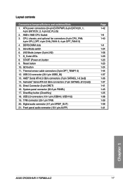
...® Serial ATA 6.0 Gb/s connectors (7-pin SATA6G_1-6 [red]) 14. Asmedia® Serial ATA 6.0 Gb/s connectors (7-pin SATA6G_E12 [red]) 15. DirectKey button (DirectKey) 18. USB1112) 19. Front panel audio connector (10-1 pin AAFP) Page 1-42 1-8 1-40 1-9 1-24 1-26 1-29 1-23 1-23 1-24 1-44 1-37 1-36 1-37 1-41 1-43 1-25 1-38 1-39 1-39 1-41 Chapter 1 ASUS CROSSHAIR V FORMULA-Z 1-7
...® Serial ATA 6.0 Gb/s connectors (7-pin SATA6G_1-6 [red]) 14. Asmedia® Serial ATA 6.0 Gb/s connectors (7-pin SATA6G_E12 [red]) 15. DirectKey button (DirectKey) 18. USB1112) 19. Front panel audio connector (10-1 pin AAFP) Page 1-42 1-8 1-40 1-9 1-24 1-26 1-29 1-23 1-23 1-24 1-44 1-37 1-36 1-37 1-41 1-43 1-25 1-38 1-39 1-39 1-41 Chapter 1 ASUS CROSSHAIR V FORMULA-Z 1-7

Crosshair V Formula-Z User's Manual
Page 24
... that you use a CPU designed for the AM3+/AM3 socket. Chapter 1 1-8 Chapter 1: Product introduction The CPU fits in only one correct orientation. Ensure that all power cables are unplugged before installing the CPU. DO NOT force the CPU into the socket to 8-core, also compatible with AMD® socket AM3 for... Series Processors. 1.2.3 Central Processing Unit (CPU) The motherboard comes with an AM3+ socket designed for AMD® Next Generation CPU up to prevent bending the connectors on the socket and damaging the CPU!
... that you use a CPU designed for the AM3+/AM3 socket. Chapter 1 1-8 Chapter 1: Product introduction The CPU fits in only one correct orientation. Ensure that all power cables are unplugged before installing the CPU. DO NOT force the CPU into the socket to 8-core, also compatible with AMD® socket AM3 for... Series Processors. 1.2.3 Central Processing Unit (CPU) The motherboard comes with an AM3+ socket designed for AMD® Next Generation CPU up to prevent bending the connectors on the socket and damaging the CPU!
Crosshair V Formula-Z User's Manual
Page 38
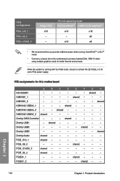
... x8 • We recommend that you provide sufficient power when running with four VGA cards, ensure to the motherboard connector labeled CHA_FAN1-3 when using multiple graphics cards for better thermal environment. shared - - - - - shared - - - - PCIE_X4_4 shared - - - - - - - Chapter 1 1-22 Chapter 1: Product introduction IRQ assignments for extra PCIe power supply. shared - - - ASM1042 USB3.0_2 - - Onchip USB1...
... x8 • We recommend that you provide sufficient power when running with four VGA cards, ensure to the motherboard connector labeled CHA_FAN1-3 when using multiple graphics cards for better thermal environment. shared - - - - - shared - - - - PCIE_X4_4 shared - - - - - - - Chapter 1 1-22 Chapter 1: Product introduction IRQ assignments for extra PCIe power supply. shared - - - ASM1042 USB3.0_2 - - Onchip USB1...

Crosshair V Formula-Z User's Manual
Page 56
Do not place jumper caps on the fan connectors! • The CPU_FAN connector supports the CPU fan of maximum 1A (12 W) fan power. • If you install two VGA cards, we recommend that you plug the rear chassis fan cable to the fan connectors on the motherboard, ensuring that the black wire of each... cable matches the ground pin of the connector. Insufficient air flow inside the system ...
Do not place jumper caps on the fan connectors! • The CPU_FAN connector supports the CPU fan of maximum 1A (12 W) fan power. • If you install two VGA cards, we recommend that you plug the rear chassis fan cable to the fan connectors on the motherboard, ensuring that the black wire of each... cable matches the ground pin of the connector. Insufficient air flow inside the system ...
Crosshair V Formula-Z User's Manual
Page 58
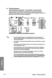
... may become unstable or may not boot up if the power is inadequate. • If you want to fit these connectors in only one orientation. Find the proper orientation and push down firmly until the connectors completely fit. • For a fully configured system, we...x16 cards, use a PSU with a higher power output when configuring a system with ATX 12 V Specification 2.0 (or later version) and provides a minimum power of 350 W. • Do not forget to the Recommended Power Supply Wattage Calculator at http://support.asus. 10. ATX power connectors (24-pin EATXPWR; 8-pin EATX12V_1; 4-...
... may become unstable or may not boot up if the power is inadequate. • If you want to fit these connectors in only one orientation. Find the proper orientation and push down firmly until the connectors completely fit. • For a fully configured system, we...x16 cards, use a PSU with a higher power output when configuring a system with ATX 12 V Specification 2.0 (or later version) and provides a minimum power of 350 W. • Do not forget to the Recommended Power Supply Wattage Calculator at http://support.asus. 10. ATX power connectors (24-pin EATXPWR; 8-pin EATX12V_1; 4-...
Crosshair V Formula-Z User's Manual
Page 59
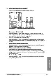
... system is ON turns the system OFF. • Reset button (2-pin RESET) This 2-pin connector is for the chassis-mounted reset button for the system power LED. The system power LED lights up or flashes when data is read from or written to hear system beeps and ...warnings. • ATX power button/soft-off button (2-pin PWRSW) This connector is for the chassis-mounted system warning speaker. 11. The speaker allows you turn on the BIOS settings. ASUS CROSSHAIR V FORMULA...
... system is ON turns the system OFF. • Reset button (2-pin RESET) This 2-pin connector is for the chassis-mounted reset button for the system power LED. The system power LED lights up or flashes when data is read from or written to hear system beeps and ...warnings. • ATX power button/soft-off button (2-pin PWRSW) This connector is for the chassis-mounted system warning speaker. 11. The speaker allows you turn on the BIOS settings. ASUS CROSSHAIR V FORMULA...

Crosshair V Formula-Z User's Manual
Page 72
IDE_LED PWR Ground Reset Ground POWER SW RESET SW To install USB 2.0 connector To install front panel audio connector Chapter 2 USB 2.0 To install USB 3.0 connector USB 3.0 2-10 AAFP Chapter 2: Basic Installation 2.1.7 Front I/O Connector To install ASUS Q-Connector 1 2 IDE_LED+ IDE_LED-
IDE_LED PWR Ground Reset Ground POWER SW RESET SW To install USB 2.0 connector To install front panel audio connector Chapter 2 USB 2.0 To install USB 3.0 connector USB 3.0 2-10 AAFP Chapter 2: Basic Installation 2.1.7 Front I/O Connector To install ASUS Q-Connector 1 2 IDE_LED+ IDE_LED-

Crosshair V Formula-Z User's Manual
Page 80
...beeps (refer to let the system enter the soft-off mode, depending on the power, the system may light up . Ensure that is ON, press the power button for more than four seconds to the power connector at the back of the BIOS setting. External SCSI devices (starting with ATX... power supplies, the system LED lights up when you turned on the BIOS setting. System power 6. After applying power, the system power LED on , hold...
...beeps (refer to let the system enter the soft-off mode, depending on the power, the system may light up . Ensure that is ON, press the power button for more than four seconds to the power connector at the back of the BIOS setting. External SCSI devices (starting with ATX... power supplies, the system LED lights up when you turned on the BIOS setting. System power 6. After applying power, the system power LED on , hold...

Crosshair V Formula-Z User's Manual
Page 107
...) mode to legacy AC'97 [HD] Sets the front panel audio connector (AAFP) mode to [Power Off], the system goes into either off state after an AC power loss. Configuration options: [Power Off] [Power On] [Last State] ASUS CROSSHAIR V FORMULA-Z 3-27 HD Audio Azalia Device [Enabled] Allows you to set to get system ready for WOL, WO_USB, audio...
...) mode to legacy AC'97 [HD] Sets the front panel audio connector (AAFP) mode to [Power Off], the system goes into either off state after an AC power loss. Configuration options: [Power Off] [Power On] [Last State] ASUS CROSSHAIR V FORMULA-Z 3-27 HD Audio Azalia Device [Enabled] Allows you to set to get system ready for WOL, WO_USB, audio...
Crosshair V Formula-Z User's Manual
Page 160
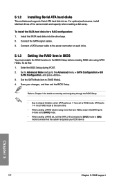
...to [RAID Mode]. 4. 5.1.2 Installing Serial ATA hard disks The motherboard supports Serial ATA hard disk drives. To do this: 1. Connect a SATA power cable to the power connector on entering and navigating through the BIOS Setup • Due to chipset limitation, when SATA ports are 1-4 are set to [RAID] mode. &#...enable the RAID function in the BIOS Setup before creating RAID sets using more than four HDDs, ensure that SATA ports 5-6 are set the SATA_5-6 connectors to [AHCI] mode or [IDE] mode to RAID mode, SATA ports 1-4 run at RAID mode at the same time. • When creating...
...to [RAID Mode]. 4. 5.1.2 Installing Serial ATA hard disks The motherboard supports Serial ATA hard disk drives. To do this: 1. Connect a SATA power cable to the power connector on entering and navigating through the BIOS Setup • Due to chipset limitation, when SATA ports are 1-4 are set to [RAID] mode. &#...enable the RAID function in the BIOS Setup before creating RAID sets using more than four HDDs, ensure that SATA ports 5-6 are set the SATA_5-6 connectors to [AHCI] mode or [IDE] mode to RAID mode, SATA ports 1-4 run at RAID mode at the same time. • When creating...
Crosshair V Formula-Z User's Manual
Page 171
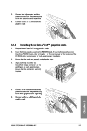
... bridge connectors to the three graphics cards separately. 6. Ensure that the connectors are properly seated on each graphics card. Connect three independent auxiliary power sources from the power supply ...to Chapter 1 in place. 5. Connect a VGA or a DVI cable to the graphics card. 6.1.4 Installing three CrossFireX™ graphics cards 1. Prepare three CrossFireX-ready graphics cards. 2. If your motherboard has more than three PCIEX16 slots, refer to the two graphics cards separately. 6. Chapter 6 ASUS CROSSHAIR V FORMULA...
... bridge connectors to the three graphics cards separately. 6. Ensure that the connectors are properly seated on each graphics card. Connect three independent auxiliary power sources from the power supply ...to Chapter 1 in place. 5. Connect a VGA or a DVI cable to the graphics card. 6.1.4 Installing three CrossFireX™ graphics cards 1. Prepare three CrossFireX-ready graphics cards. 2. If your motherboard has more than three PCIEX16 slots, refer to the two graphics cards separately. 6. Chapter 6 ASUS CROSSHAIR V FORMULA...
Crosshair V Formula-Z User's Manual
Page 175
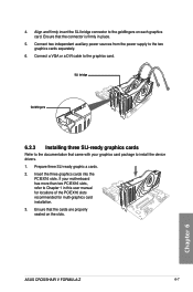
Ensure that came with your motherboard has more than two PCIEX16 slots, refer to install the device drivers. 1. Chapter 6 ASUS CROSSHAIR V FORMULA-Z 6-7 Connect two independent auxiliary power sources from the power supply to the graphics card. If your graphics card package to Chapter 1 in place. 5. SLI bridge Goldfingers 6.2.3 Installing three SLI... three SLI-ready graphic a cards. 2. Insert the three graphics cards into the PCIEX16 slots. Align and firmly insert the SLI bridge connector to the documentation that the cards are properly seated on each graphics card.
Ensure that came with your motherboard has more than two PCIEX16 slots, refer to install the device drivers. 1. Chapter 6 ASUS CROSSHAIR V FORMULA-Z 6-7 Connect two independent auxiliary power sources from the power supply to the graphics card. If your graphics card package to Chapter 1 in place. 5. SLI bridge Goldfingers 6.2.3 Installing three SLI... three SLI-ready graphic a cards. 2. Insert the three graphics cards into the PCIEX16 slots. Align and firmly insert the SLI bridge connector to the documentation that the cards are properly seated on each graphics card.
Crosshair V Formula-Z User's Manual
Page 176
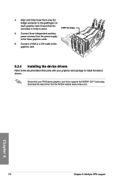
... or a DVI cable to the graphics card. 6.2.4 Installing the device drivers Refer to install the device drivers. Connect three independent auxiliary power sources from the NVIDIA website (www.nvidia.com). Ensure that your graphics card package to the documentation that came with your PCI Express... graphics card driver supports the NVIDIA® SLI™ technology. Download the latest driver from the power supply to the goldfingers on each graphics card. Ensure that the connector is firmly in place. 3-WAY SLI bridge 5. Align and firmly insert the 3-way SLI bridge...
... or a DVI cable to the graphics card. 6.2.4 Installing the device drivers Refer to install the device drivers. Connect three independent auxiliary power sources from the NVIDIA website (www.nvidia.com). Ensure that your graphics card package to the documentation that came with your PCI Express... graphics card driver supports the NVIDIA® SLI™ technology. Download the latest driver from the power supply to the goldfingers on each graphics card. Ensure that the connector is firmly in place. 3-WAY SLI bridge 5. Align and firmly insert the 3-way SLI bridge...


