User Manual
Page 4
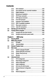
... 2-34 2.3.3 CPU heatsink and fan assembly installation 2-35 2.3.4 DIMM installation 2-38 2.3.5 Motherboard installation 2-39 2.3.6 ATX Power connection 2-41 2.3.7 SATA device connection 2-42 2.3.8 Front I/O Connector 2-43 2.3.9 Expension Card installation 2-44 2.3.10 ROG ThunderBolt Installation 2-45 2.3.11 Rear panel connectors 2-47 2.3.12 Audio I/O connections 2-48 2.4 Starting up for the first time 2-51 2.5 Turning off the...
... 2-34 2.3.3 CPU heatsink and fan assembly installation 2-35 2.3.4 DIMM installation 2-38 2.3.5 Motherboard installation 2-39 2.3.6 ATX Power connection 2-41 2.3.7 SATA device connection 2-42 2.3.8 Front I/O Connector 2-43 2.3.9 Expension Card installation 2-44 2.3.10 ROG ThunderBolt Installation 2-45 2.3.11 Rear panel connectors 2-47 2.3.12 Audio I/O connections 2-48 2.4 Starting up for the first time 2-51 2.5 Turning off the...

User Manual
Page 12
... the product, contact a qualified service technician or your dealer immediately. • To avoid short circuits, keep paper clips, screws, and staples away from connectors, slots, sockets and circuitry. • Avoid dust, humidity, and temperature extremes. Check local regulations for disposal of parts and recycling. DO NOT throw .... If you encounter technical problems with the package. • Before using the product, ensure all cables are correctly connected and the power cables are not damaged. This product has been designed to enable proper reuse of electronic products.
... the product, contact a qualified service technician or your dealer immediately. • To avoid short circuits, keep paper clips, screws, and staples away from connectors, slots, sockets and circuitry. • Avoid dust, humidity, and temperature extremes. Check local regulations for disposal of parts and recycling. DO NOT throw .... If you encounter technical problems with the package. • Before using the product, ensure all cables are correctly connected and the power cables are not damaged. This product has been designed to enable proper reuse of electronic products.
User Manual
Page 16
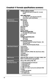
...+ - 8+2 phase CPU power design CPU Level Up MemOK! ASUS C.P.R.(CPU Parameter Recall) Core Unlocker ASUS Fan Xpert ASUS Q-Connector ASUS Q-Shield ASUS Q- LED (CPU, DRAM, VGA, Boot Device LEDs) Ai Charger+ ASUS EZ Flash 2 ASUS MyLogo 3 32Mb Flash ROM...CMOS switch (continued on the next page) Profile Overclocking Protection: - Voltiminder LED - RC Diagram - ASUS TPU - COP EX (Component Overheat Protection - O.C. EX) - Crosshair V Formula specifications summary USB ROG Exclusive Overclocking Features Other Special Features BIOS Features Manageability Back Panel I/O Ports xvi ...
...+ - 8+2 phase CPU power design CPU Level Up MemOK! ASUS C.P.R.(CPU Parameter Recall) Core Unlocker ASUS Fan Xpert ASUS Q-Connector ASUS Q-Shield ASUS Q- LED (CPU, DRAM, VGA, Boot Device LEDs) Ai Charger+ ASUS EZ Flash 2 ASUS MyLogo 3 32Mb Flash ROM...CMOS switch (continued on the next page) Profile Overclocking Protection: - Voltiminder LED - RC Diagram - ASUS TPU - COP EX (Component Overheat Protection - O.C. EX) - Crosshair V Formula specifications summary USB ROG Exclusive Overclocking Features Other Special Features BIOS Features Manageability Back Panel I/O Ports xvi ...
User Manual
Page 17
xvii Crosshair V Formula specifications summary Internal I/O Connectors Software Form Factor 1 x USB 3.0/2.0 connector supports additional 2 USB 3.0/2.0 ports 2 x USB 2.0/1.1 connectors support additional 4 USB 2.0/1.1 ports 7 x SATA 6Gb/s connectors (Red) 8 x Fan connectors: 2 x CPU / 3 x Chassis / 3x Optional 8 x ProbeIt measurement points 3 x Thermal sensor connectors 1 x SPDIF_out connector 1 x 24-pin ATX power connector 1 x 8-pin ATX 12V power connector 1 x 4-pin ATX 12V power connector 1 x EZ Plug connector (4-pin Molex Power connector) 1 x En/Dis-able Clr CMOS header 1 x CPU...
xvii Crosshair V Formula specifications summary Internal I/O Connectors Software Form Factor 1 x USB 3.0/2.0 connector supports additional 2 USB 3.0/2.0 ports 2 x USB 2.0/1.1 connectors support additional 4 USB 2.0/1.1 ports 7 x SATA 6Gb/s connectors (Red) 8 x Fan connectors: 2 x CPU / 3 x Chassis / 3x Optional 8 x ProbeIt measurement points 3 x Thermal sensor connectors 1 x SPDIF_out connector 1 x 24-pin ATX power connector 1 x 8-pin ATX 12V power connector 1 x 4-pin ATX 12V power connector 1 x EZ Plug connector (4-pin Molex Power connector) 1 x En/Dis-able Clr CMOS header 1 x CPU...
User Manual
Page 33
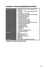
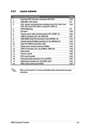
... RTC RAM (3-pin CLRTC_SW) 11. Digital audio connector (4-1 pin SPDIF_OUT) 18. AMD SB950 Serial ATA connectors (7-pin SATA6G 1-6) 9. ROG Crosshair V Formula 2-3 2.2.2 Layout contents Connectors/Jumpers/Switches/Slots 1. 8-pin/4-pin ATX 12V power connectors; System panel connector (20-8 pin PANEL) 12. Power-on switch 15. USB3.0 connectors (18-1 pin USB3_56) 8. Asmedia Serial ATA 6Gb/s connectors (7-pin SATA6G_E1) 10. DDR3 DIMM slots 5. ROG...
... RTC RAM (3-pin CLRTC_SW) 11. Digital audio connector (4-1 pin SPDIF_OUT) 18. AMD SB950 Serial ATA connectors (7-pin SATA6G 1-6) 9. ROG Crosshair V Formula 2-3 2.2.2 Layout contents Connectors/Jumpers/Switches/Slots 1. 8-pin/4-pin ATX 12V power connectors; System panel connector (20-8 pin PANEL) 12. Power-on switch 15. USB3.0 connectors (18-1 pin USB3_56) 8. Asmedia Serial ATA 6Gb/s connectors (7-pin SATA6G_E1) 10. DDR3 DIMM slots 5. ROG...
User Manual
Page 34
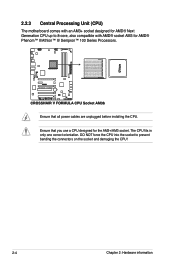
Ensure that all power cables are unplugged before installing the CPU. The CPU fits in only one correct orientation. DO NOT force the CPU into the socket to 8-core, also compatible with AMD® socket AM3 for AMD® Phenom™ II/Athlon™ II/ Sempron™ 100 Series Processors. Ensure that you use a CPU designed for the AM3+/AM3 socket. 2.2.3 Central Processing Unit (CPU) The motherboard comes with an AM3+ socket designed for AMD® Next Generation CPU up to prevent bending the connectors on the socket and damaging the CPU! 2-4 Chapter 2: Hardware information
Ensure that all power cables are unplugged before installing the CPU. The CPU fits in only one correct orientation. DO NOT force the CPU into the socket to 8-core, also compatible with AMD® socket AM3 for AMD® Phenom™ II/Athlon™ II/ Sempron™ 100 Series Processors. Ensure that you use a CPU designed for the AM3+/AM3 socket. 2.2.3 Central Processing Unit (CPU) The motherboard comes with an AM3+ socket designed for AMD® Next Generation CPU up to prevent bending the connectors on the socket and damaging the CPU! 2-4 Chapter 2: Hardware information

User Manual
Page 42
The following sub‑sections describe the slots and the expansion cards that you intend to unplug the power cord before adding or removing expansion cards. Installing an expansion card To install an expansion card: 1. Keep the screw for the card. 2. Otherwise, ...). 3. Remove the system unit cover (if your motherboard is completely seated on the next page for details. 2-12 Chapter 2: Hardware information Align the card connector with the screw you removed earlier. 6. Secure the card to do not need to the table on the slot. 5. Remove the bracket opposite the slot...
The following sub‑sections describe the slots and the expansion cards that you intend to unplug the power cord before adding or removing expansion cards. Installing an expansion card To install an expansion card: 1. Keep the screw for the card. 2. Otherwise, ...). 3. Remove the system unit cover (if your motherboard is completely seated on the next page for details. 2-12 Chapter 2: Hardware information Align the card connector with the screw you removed earlier. 6. Secure the card to do not need to the table on the slot. 5. Remove the bracket opposite the slot...

User Manual
Page 44
... slots will work at x16, x8, x8 link as the default. • We recommend that you provide sufficient power when running CrossFireX™ or SLI™ mode. • Connect a chassis fan to the motherboard connector labeled CHA_FAN1/2/3 when using multiple graphics cards for this motherboard A B C D E F G H Intel 82583V - - - - - PCI Slot - - - - PCIE_X4_4 shared - - - - - - - PCIE_X1_1...
... slots will work at x16, x8, x8 link as the default. • We recommend that you provide sufficient power when running CrossFireX™ or SLI™ mode. • Connect a chassis fan to the motherboard connector labeled CHA_FAN1/2/3 when using multiple graphics cards for this motherboard A B C D E F G H Intel 82583V - - - - - PCI Slot - - - - PCIE_X4_4 shared - - - - - - - PCIE_X1_1...
User Manual
Page 56
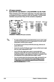
...://support.asus.com/PowerSupplyCalculator/PSCalculator. aspx?SLanguage=en-us for your system, refer to ensure sufficient power supply when you use a power supply unit (PSU) that complies with ATX 12 V Specification 2.0 (or later version) and provides a minimum power of a PSU with more power-consuming devices. Find the proper orientation and push down firmly until the connectors...
...://support.asus.com/PowerSupplyCalculator/PSCalculator. aspx?SLanguage=en-us for your system, refer to ensure sufficient power supply when you use a power supply unit (PSU) that complies with ATX 12 V Specification 2.0 (or later version) and provides a minimum power of a PSU with more power-consuming devices. Find the proper orientation and push down firmly until the connectors...
User Manual
Page 57
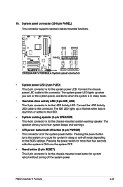
...8226; Hard disk drive activity LED (2-pin IDE_LED) This 2-pin connector is for the chassis-mounted reset button for the system power LED. ROG Crosshair V Formula 2-27 The IDE LED lights up when you to this connector. Pressing the power switch for more than four seconds while the system is ON ...turns the system OFF. • Reset button (2-pin RESET) This 2-pin connector is for the chassis...
...8226; Hard disk drive activity LED (2-pin IDE_LED) This 2-pin connector is for the chassis-mounted reset button for the system power LED. ROG Crosshair V Formula 2-27 The IDE LED lights up when you to this connector. Pressing the power switch for more than four seconds while the system is ON ...turns the system OFF. • Reset button (2-pin RESET) This 2-pin connector is for the chassis...

User Manual
Page 58
...chassis front panel cables. Refer to their respective front panel cable labels. Install the ASUS Q-Connector to the system panel connector, ensuring the orientation matches the labels on the Q-Connector to know the detailed pin definitions, and then match them to the labels on the... motherboard. 3. The figure shows the QConnector is properly installed on the chassis model. ASUS Q-Connector (system panel) Use the ASUS Q-Connector to the ASUS Q-Connector. The labels on the front panel cables may vary depending on the motherboard. 2-28 Chapter 2: Hardware information...
...chassis front panel cables. Refer to their respective front panel cable labels. Install the ASUS Q-Connector to the system panel connector, ensuring the orientation matches the labels on the Q-Connector to know the detailed pin definitions, and then match them to the labels on the... motherboard. 3. The figure shows the QConnector is properly installed on the chassis model. ASUS Q-Connector (system panel) Use the ASUS Q-Connector to the ASUS Q-Connector. The labels on the front panel cables may vary depending on the motherboard. 2-28 Chapter 2: Hardware information...
User Manual
Page 76
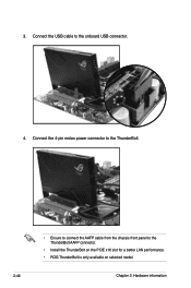
Connect the USB cable to the ThunderBolt AAFP connector. • Install the ThunderBolt on the PCIE x16 slot for a better LAN performance. • ROG ThunderBolt is only available on selected model. 2-46 Chapter 2: Hardware information Connect the 4-pin molex power connector to the ThunderBolt. • Ensure to connect the AAFP cable from the chassis front panel to the onboard USB connector. 4. 3.
Connect the USB cable to the ThunderBolt AAFP connector. • Install the ThunderBolt on the PCIE x16 slot for a better LAN performance. • ROG ThunderBolt is only available on selected model. 2-46 Chapter 2: Hardware information Connect the 4-pin molex power connector to the ThunderBolt. • Ensure to connect the AAFP cable from the chassis front panel to the onboard USB connector. 4. 3.
User Manual
Page 81
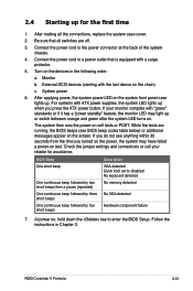
...on test. BIOS Beep Description One short beep VGA detected Quick boot set to the power connector at the back of the system chassis. 4. Follow the instructions in the following order: a. Connect the power cord to enter the BIOS Setup. Turn on self tests or POST. External SCSI... you turned on the chain) c. For systems with "green" standards or if it has a "power standby" feature, the monitor LED may have failed a power-on the screen. System power 6. ROG Crosshair V Formula 2-51 If your retailer for the first time 1. Check the jumper settings and connections or call your...
...on test. BIOS Beep Description One short beep VGA detected Quick boot set to the power connector at the back of the system chassis. 4. Follow the instructions in the following order: a. Connect the power cord to enter the BIOS Setup. Turn on self tests or POST. External SCSI... you turned on the chain) c. For systems with "green" standards or if it has a "power standby" feature, the monitor LED may have failed a power-on the screen. System power 6. ROG Crosshair V Formula 2-51 If your retailer for the first time 1. Check the jumper settings and connections or call your...
User Manual
Page 85
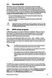
... The BIOS setup program can be used under the Exit menu. ROG Crosshair V Formula 3-1 3.1 Knowing BIOS BIOS (Basic Input and Output System) stores system hardware settings such as storage device configuration, overclocking settings, advanced power management, and boot device configuration that you change the BIOS settings only ... turn the system off and then turn it lets you want to use as easy to boot. See section 2.3.11 Rear panel connectors for BIOS item modification. When you start up the computer, the system provides you wish to enter Setup after changing any BIOS ...
... The BIOS setup program can be used under the Exit menu. ROG Crosshair V Formula 3-1 3.1 Knowing BIOS BIOS (Basic Input and Output System) stores system hardware settings such as storage device configuration, overclocking settings, advanced power management, and boot device configuration that you change the BIOS settings only ... turn the system off and then turn it lets you want to use as easy to boot. See section 2.3.11 Rear panel connectors for BIOS item modification. When you start up the computer, the system provides you wish to enter Setup after changing any BIOS ...

User Manual
Page 173
... SATA hard disks into the drive bays. 2. Save your changes, and then exit the BIOS Setup. ROG Crosshair V Formula 4-39 Connect a SATA power cable to the Advanced menu > SATA Configuration, and then press . 3. Go to the power connector on entering and navigating through the BIOS Setup. When setting the SATA Port1-Port4 item to Chapter...
... SATA hard disks into the drive bays. 2. Save your changes, and then exit the BIOS Setup. ROG Crosshair V Formula 4-39 Connect a SATA power cable to the Advanced menu > SATA Configuration, and then press . 3. Go to the power connector on entering and navigating through the BIOS Setup. When setting the SATA Port1-Port4 item to Chapter...

User Manual
Page 184
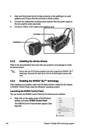
...and the motherboard layout may vary with models, but the installation steps remain the same. 1. Align and firmly insert the CrossFireX bridge connector to the goldfingers on the slots. 4. CrossFireX bridge 5. Goldfingers 5-2 Chapter 5: Multiple GPU technology support Insert the two graphics card ...into the PCIEX16 slots. 3. Connect two independent auxiliary power sources from the power supply to the graphics card. Connect a VGA or a DVI cable to the two graphics cards separately. 6. Ensure that the connector is firmly in place. 5.1.3 Installing CrossFireX graphics cards ...
...and the motherboard layout may vary with models, but the installation steps remain the same. 1. Align and firmly insert the CrossFireX bridge connector to the goldfingers on the slots. 4. CrossFireX bridge 5. Goldfingers 5-2 Chapter 5: Multiple GPU technology support Insert the two graphics card ...into the PCIEX16 slots. 3. Connect two independent auxiliary power sources from the power supply to the graphics card. Connect a VGA or a DVI cable to the two graphics cards separately. 6. Ensure that the connector is firmly in place. 5.1.3 Installing CrossFireX graphics cards ...
User Manual
Page 188
...NVIDIA Control Panel. Download the latest driver from the power supply to install the device drivers. Ensure that your PCI Express graphics card driver supports the NVIDIA® SLI™ technology. Ensure that the connector is firmly in NVIDIA® Control Panel under ...the Windows® operating system. Connect two independent auxiliary power sources from the NVIDIA website (www.nvidia. com). 5.2.4 Enabling the NVIDIA®...
...NVIDIA Control Panel. Download the latest driver from the power supply to install the device drivers. Ensure that your PCI Express graphics card driver supports the NVIDIA® SLI™ technology. Ensure that the connector is firmly in NVIDIA® Control Panel under ...the Windows® operating system. Connect two independent auxiliary power sources from the NVIDIA website (www.nvidia. com). 5.2.4 Enabling the NVIDIA®...


