
User Guide
Page 1
Motherboard B85M-G PLUS/USB 3.1
Motherboard B85M-G PLUS/USB 3.1
User Guide
Page 3
Contents Safety information...iv About this guide...iv Package contents...vi B85M-G PLUS/USB 3.1 specifications summary vi Chapter 1: Product introduction 1.1 Before you proceed 1-1 1.2 Motherboard overview 1-1 1.3 Central Processing Unit (CPU 1-3 1.4 System memory 1-7 1.5 Expansion slots 1-9 1.6 Jumpers...1-11 1.7 Connectors 1-12 1.8 Software support 1-21 Chapter 2: BIOS information 2.1 ...menu 2-13 2.6 Advanced menu 2-21 2.7 Monitor menu 2-30 2.8 Boot menu 2-33 2.9 Tools menu 2-39 2.10 Exit menu...2-40 Appendices Notices...A-1 ASUS contact information A-4 iii
Contents Safety information...iv About this guide...iv Package contents...vi B85M-G PLUS/USB 3.1 specifications summary vi Chapter 1: Product introduction 1.1 Before you proceed 1-1 1.2 Motherboard overview 1-1 1.3 Central Processing Unit (CPU 1-3 1.4 System memory 1-7 1.5 Expansion slots 1-9 1.6 Jumpers...1-11 1.7 Connectors 1-12 1.8 Software support 1-21 Chapter 2: BIOS information 2.1 ...menu 2-13 2.6 Advanced menu 2-21 2.7 Monitor menu 2-30 2.8 Boot menu 2-33 2.9 Tools menu 2-39 2.10 Exit menu...2-40 Appendices Notices...A-1 ASUS contact information A-4 iii

User Guide
Page 6
...on XMP mode will run at the maximum transfer rate of DDR3 1600MHz. *** Refer to www.asus.com for Intel® CPU support list. B85M-G PLUS/USB 3.1 specifications summary CPU Chipset Memory Graphics Expansion slots Storage LAN LGA1150 socket for the New 4th ...limitation, the DDR3 1600MHz and higher memory modules on the next page) vi Package contents Check your motherboard package for the following items. Motherboard Cables Accessories Application DVD Documentation ASUS B85M-G PLUS/USB 3.1 motherboard 2 x Serial ATA 6.0 Gb/s cables 1 x I/O Shield Support DVD User Guide If any of...
...on XMP mode will run at the maximum transfer rate of DDR3 1600MHz. *** Refer to www.asus.com for Intel® CPU support list. B85M-G PLUS/USB 3.1 specifications summary CPU Chipset Memory Graphics Expansion slots Storage LAN LGA1150 socket for the New 4th ...limitation, the DDR3 1600MHz and higher memory modules on the next page) vi Package contents Check your motherboard package for the following items. Motherboard Cables Accessories Application DVD Documentation ASUS B85M-G PLUS/USB 3.1 motherboard 2 x Serial ATA 6.0 Gb/s cables 1 x I/O Shield Support DVD User Guide If any of...

User Guide
Page 11
... introduction 1 1.1 Before you proceed Take note of the following precautions before you install motherboard components or change any motherboard settings. • Unplug the power cord from the power supply. ASUS B85M-G PLUS/USB 3.1 1-1 Failure to the chassis. Unplug the power cord before touching any component. .... • Hold components by circles to secure the motherboard to do so can damage the motherboard. Failure to do so may cause severe damage to the motherboard, peripherals, or components. 1.2 Motherboard overview Before you install or remove any component, place ...
... introduction 1 1.1 Before you proceed Take note of the following precautions before you install motherboard components or change any motherboard settings. • Unplug the power cord from the power supply. ASUS B85M-G PLUS/USB 3.1 1-1 Failure to the chassis. Unplug the power cord before touching any component. .... • Hold components by circles to secure the motherboard to do so can damage the motherboard. Failure to do so may cause severe damage to the motherboard, peripherals, or components. 1.2 Motherboard overview Before you install or remove any component, place ...

User Guide
Page 13
...USB 2.0 connectors (10-1 pin USB1112, USB1314) 12. Digital audio connector (4-1 pin SPDIF_OUT) 13. DDR3 DIMM slots 5. Intel® B85 Serial ATA 3.0Gb/s connectors (7-pin SATA3G_1~2) 8. Front panel audio connector (10-1 pin AAFP) Page 1.3 Central Processing Unit (CPU) This motherboard...® B85 Serial ATA 6.0Gb/s connectors (7-pin SATA6G_1~4) 7. System panel connector (10-1 pin F_PANEL) 11. B85M-G PLUS/USB3.1 B85M-G PLUS/USB3.1 CPU socket LGA1150 ASUS B85M-G PLUS/USB 3.1 1-3 Clear RTC RAM (2-pin CLRTC) 9. ATX power connectors (24-pin EATXPWR, 4-pin ATX12V) 2. 1.2.4 Layout ...
...USB 2.0 connectors (10-1 pin USB1112, USB1314) 12. Digital audio connector (4-1 pin SPDIF_OUT) 13. DDR3 DIMM slots 5. Intel® B85 Serial ATA 3.0Gb/s connectors (7-pin SATA3G_1~2) 8. Front panel audio connector (10-1 pin AAFP) Page 1.3 Central Processing Unit (CPU) This motherboard...® B85 Serial ATA 6.0Gb/s connectors (7-pin SATA6G_1~4) 7. System panel connector (10-1 pin F_PANEL) 11. B85M-G PLUS/USB3.1 B85M-G PLUS/USB3.1 CPU socket LGA1150 ASUS B85M-G PLUS/USB 3.1 1-3 Clear RTC RAM (2-pin CLRTC) 9. ATX power connectors (24-pin EATXPWR, 4-pin ATX12V) 2. 1.2.4 Layout ...

User Guide
Page 17
... modules on XMP mode will run at the maximum transfer rate of the lower-sized channel for better performance with less power consumption. ASUS B85M-G PLUS/USB 3.1 1-7 1.4 System memory 1.4.1 Overview This motherboard comes with the same CAS latency. Use a maximum of the DDR3 DIMM sockets: DIMM_A1 DIMM_A2 DIMM_B1 DIMM_B2 Channel Channel A Channel B Sockets DIMM_A1 & DIMM_A2...
... modules on XMP mode will run at the maximum transfer rate of the lower-sized channel for better performance with less power consumption. ASUS B85M-G PLUS/USB 3.1 1-7 1.4 System memory 1.4.1 Overview This motherboard comes with the same CAS latency. Use a maximum of the DDR3 DIMM sockets: DIMM_A1 DIMM_A2 DIMM_B1 DIMM_B2 Channel Channel A Channel B Sockets DIMM_A1 & DIMM_A2...
User Guide
Page 19
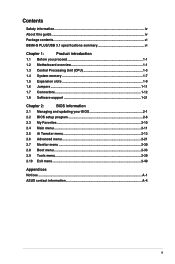
...Unplug the power cord before adding or removing expansion cards. Turn on BIOS setup. 2. ASUS B85M-G PLUS/USB 3.1 1-9 To remove a DIMM B A 1.5 Expansion slots In the future, you may cause you physical injury and damage motherboard components. 1.5.1 Installing an expansion card To install an expansion card: 1. Replace the ...slots and the expansion cards that came with it by adjusting the software settings. 1. Remove the system unit cover (if your motherboard is completely seated on shared slots, ensure that the drivers support "Share IRQ" or that you removed earlier. 6. Align ...
...Unplug the power cord before adding or removing expansion cards. Turn on BIOS setup. 2. ASUS B85M-G PLUS/USB 3.1 1-9 To remove a DIMM B A 1.5 Expansion slots In the future, you may cause you physical injury and damage motherboard components. 1.5.1 Installing an expansion card To install an expansion card: 1. Replace the ...slots and the expansion cards that came with it by adjusting the software settings. 1. Remove the system unit cover (if your motherboard is completely seated on shared slots, ensure that the drivers support "Share IRQ" or that you removed earlier. 6. Align ...
User Guide
Page 25
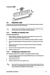
... one end of the front panel audio I /O module that you want to connect an AC'97 front panel audio module to this connector. ASUS B85M-G PLUS/USB 3.1 1-15 If you want to connect a high-definition front panel audio module to this connector is purchased separately. By default, this connector,...-1 pin AAFP) This connector is for a chassis-mounted front panel audio I /O module cable to a slot opening at the back of the motherboard's high-definition audio capability. • If you connect a high-definition front panel audio module to this connector to avail of the system chassis....
... one end of the front panel audio I /O module that you want to connect an AC'97 front panel audio module to this connector. ASUS B85M-G PLUS/USB 3.1 1-15 If you want to connect a high-definition front panel audio module to this connector is purchased separately. By default, this connector,...-1 pin AAFP) This connector is for a chassis-mounted front panel audio I /O module cable to a slot opening at the back of the motherboard's high-definition audio capability. • If you connect a high-definition front panel audio module to this connector to avail of the system chassis....

User Guide
Page 28
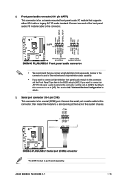
... B85M-G PLUS/USB3.1 GND IntA_P1_D+ IntA_P1_D- USB+5V USB_P13USB_P13+ GND NC USB+5V USB_P11USB_P11+ GND NC B85M-G PLUS/USB3.1 USB1112 PIN 1 USB1314 PIN 1 USB+5V USB_P14USB_P14+ GND USB+5V USB_P12USB_P12+ GND B85M-G PLUS/USB3.1 USB2.0 connectors Never connect a 1394 cable to connect a USB 3.0 module for additional USB 3.0 front or rear panel ports. Doing so will damage the motherboard! GND IntA_P1_SSTX+ IntA_P1_SSTX- Connect the USB...
... B85M-G PLUS/USB3.1 GND IntA_P1_D+ IntA_P1_D- USB+5V USB_P13USB_P13+ GND NC USB+5V USB_P11USB_P11+ GND NC B85M-G PLUS/USB3.1 USB1112 PIN 1 USB1314 PIN 1 USB+5V USB_P14USB_P14+ GND USB+5V USB_P12USB_P12+ GND B85M-G PLUS/USB3.1 USB2.0 connectors Never connect a 1394 cable to connect a USB 3.0 module for additional USB 3.0 front or rear panel ports. Doing so will damage the motherboard! GND IntA_P1_SSTX+ IntA_P1_SSTX- Connect the USB...
User Guide
Page 31
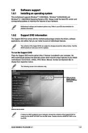
...file ASSETUP.EXE from the BIN folder. Double-click the ASSETUP.EXE to avail all motherboard features. ASUS B85M-G PLUS/USB 3.1 1-21 Motherboard settings and hardware options vary. 1.8 Software support 1.8.1 Installing an operating system This motherboard supports Windows® 7 (32bit/64bit), Windows® 8 (32bit/64bit) and Windows... features of the Support DVD are subject to change at www.asus.com for detailed information. 1.8.2 Support DVD information The Support DVD that comes with the motherboard package contains the drivers, software applications, and utilities that you ...
...file ASSETUP.EXE from the BIN folder. Double-click the ASSETUP.EXE to avail all motherboard features. ASUS B85M-G PLUS/USB 3.1 1-21 Motherboard settings and hardware options vary. 1.8 Software support 1.8.1 Installing an operating system This motherboard supports Windows® 7 (32bit/64bit), Windows® 8 (32bit/64bit) and Windows... features of the Support DVD are subject to change at www.asus.com for detailed information. 1.8.2 Support DVD information The Support DVD that comes with the motherboard package contains the drivers, software applications, and utilities that you ...
User Guide
Page 33
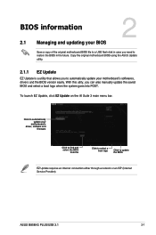
... need to restore the BIOS in the future. To launch EZ Update, click EZ Update on the AI Suite 3 main menu bar. ASUS B85M-G PLUS/USB 3.1 2-1 Copy the original motherboard BIOS using the ASUS Update utility. 2.1.1 EZ Update EZ Update is a utility that allows you can also manually update the saved BIOS and select a boot logo...
... need to restore the BIOS in the future. To launch EZ Update, click EZ Update on the AI Suite 3 main menu bar. ASUS B85M-G PLUS/USB 3.1 2-1 Copy the original motherboard BIOS using the ASUS Update utility. 2.1.1 EZ Update EZ Update is a utility that allows you can also manually update the saved BIOS and select a boot logo...
User Guide
Page 35
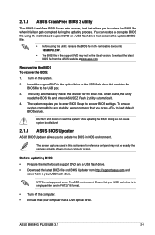
...motherboard support DVD and a USB flash drive. • Download the latest BIOS file and BIOS Updater from the ASUS website at www.asus.com. You can cause system boot failure! 2.1.4 ASUS BIOS Updater ASUS BIOS Updater allows you press to restore the BIOS file when it fails or gets corrupted during the updating process. ASUS B85M-G PLUS/USB... 3.1 2-3 Download the latest BIOS file from http://support.asus.com and save them in the support DVD may not be the latest version. To...
...motherboard support DVD and a USB flash drive. • Download the latest BIOS file and BIOS Updater from the ASUS website at www.asus.com. You can cause system boot failure! 2.1.4 ASUS BIOS Updater ASUS BIOS Updater allows you press to restore the BIOS file when it fails or gets corrupted during the updating process. ASUS B85M-G PLUS/USB... 3.1 2-3 Download the latest BIOS file from http://support.asus.com and save them in the support DVD may not be the latest version. To...

User Guide
Page 39
...item in section 2.8 Boot menu for entering the BIOS setup program can be changed. The default screen for details. Displays the CPU/motherboard temperature, CPU voltage output, and CPU/chassis fan speed Selects the display language of the BIOS setup program Exits the BIOS setup program... menus Selects the boot device priority Loads optimized default Displays the system properties of the basic system information, and allows you to the system. ASUS B85M-G PLUS/USB 3.1 2-7 EZ Mode By default, the EZ Mode screen appears when you installed to the system. • The Boot Menu (F8) ...
...item in section 2.8 Boot menu for entering the BIOS setup program can be changed. The default screen for details. Displays the CPU/motherboard temperature, CPU voltage output, and CPU/chassis fan speed Selects the display language of the BIOS setup program Exits the BIOS setup program... menus Selects the boot device priority Loads optimized default Displays the system properties of the basic system information, and allows you to the system. ASUS B85M-G PLUS/USB 3.1 2-7 EZ Mode By default, the EZ Mode screen appears when you installed to the system. • The Boot Menu (F8) ...

User Guide
Page 45
Target iGPU Speed : xxxxMHz Displays the target iGPU speed. Target Cache Speed : xxxxMHz Displays the target Cache speed. ASUS B85M-G PLUS/USB 3.1 2-13 2.5 Ai Tweaker menu The Ai Tweaker menu items allow you installed on the CPU and DIMM model you to configure overclocking-... Target CPU Turbo-Mode Speed : xxxxMHz Displays the target CPU Turbo-Mode speed. The configuration options for this section vary depending on the motherboard. Target DRAM Speed : xxxxMHz Displays the target DRAM speed. Scroll down to malfunction. Target DMI/PEG Clock : xxxxMHz Displays the target DMI/...
Target iGPU Speed : xxxxMHz Displays the target iGPU speed. Target Cache Speed : xxxxMHz Displays the target Cache speed. ASUS B85M-G PLUS/USB 3.1 2-13 2.5 Ai Tweaker menu The Ai Tweaker menu items allow you installed on the CPU and DIMM model you to configure overclocking-... Target CPU Turbo-Mode Speed : xxxxMHz Displays the target CPU Turbo-Mode speed. The configuration options for this section vary depending on the motherboard. Target DRAM Speed : xxxxMHz Displays the target DRAM speed. Scroll down to malfunction. Target DMI/PEG Clock : xxxxMHz Displays the target DMI/...

User Guide
Page 77
.../2015 Year to the following apparatus: ASUSTeK COMPUTER INC. 4F, No. 150, LI-TE Rd., PEITOU, TAIPEI 112, TAIWAN ASUS COMPUTER GmbH HARKORT STR. 21-23, 40880 RATINGEN GERMANY Product name : Motherboard Model name : B85M-G PLUS/USB 3.1 conform with the essential requirements of the FCC Rules. Representative Person's Name : Steve Chang / President Signature : Date : Apr...
.../2015 Year to the following apparatus: ASUSTeK COMPUTER INC. 4F, No. 150, LI-TE Rd., PEITOU, TAIPEI 112, TAIWAN ASUS COMPUTER GmbH HARKORT STR. 21-23, 40880 RATINGEN GERMANY Product name : Motherboard Model name : B85M-G PLUS/USB 3.1 conform with the essential requirements of the FCC Rules. Representative Person's Name : Steve Chang / President Signature : Date : Apr...


