
User Guide
Page 1
Motherboard B150M-PLUS D3
Motherboard B150M-PLUS D3
User Guide
Page 3
Contents Safety information iv About this guide iv Package contents vi B150M-PLUS D3 specifications summary vi Chapter 1: Product introduction 1.1 Before you proceed 1-1 1.2 Motherboard overview 1-2 1.3 Central Processing Unit (CPU 1-4 1.4 System memory 1-8 1.5 Expansion slots 1-11 1.6 Headers 1-13 1.7 Connectors 1-14 1.8 Software support 1-22 Chapter 2: BIOS information 2.1 Managing and ...10 2.5 Ai Tweaker menu 2-11 2.6 Advanced menu 2-12 2.7 Monitor menu 2-12 2.8 Boot menu 2-13 2.9 Tool menu 2-13 2.10 Exit menu 2-13 Appendices Notices...A-1 ASUS contact information A-4 iii
Contents Safety information iv About this guide iv Package contents vi B150M-PLUS D3 specifications summary vi Chapter 1: Product introduction 1.1 Before you proceed 1-1 1.2 Motherboard overview 1-2 1.3 Central Processing Unit (CPU 1-4 1.4 System memory 1-8 1.5 Expansion slots 1-11 1.6 Headers 1-13 1.7 Connectors 1-14 1.8 Software support 1-22 Chapter 2: BIOS information 2.1 Managing and ...10 2.5 Ai Tweaker menu 2-11 2.6 Advanced menu 2-12 2.7 Monitor menu 2-12 2.8 Boot menu 2-13 2.9 Tool menu 2-13 2.10 Exit menu 2-13 Appendices Notices...A-1 ASUS contact information A-4 iii
User Guide
Page 4
... supply is broken, do not try to fix it may be exposed to moisture. • Place the product on the motherboard. • Chapter 2: BIOS information This chapter discusses changing system settings through the BIOS Setup menus. If you need when installing and ...configuring the motherboard. iv It includes descriptions of the motherboard and the new technology it supports. Do not place the product in your retailer. Contact a qualified service technician ...
... supply is broken, do not try to fix it may be exposed to moisture. • Place the product on the motherboard. • Chapter 2: BIOS information This chapter discusses changing system settings through the BIOS Setup menus. If you need when installing and ...configuring the motherboard. iv It includes descriptions of the motherboard and the new technology it supports. Do not place the product in your retailer. Contact a qualified service technician ...
User Guide
Page 6
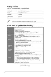
... Technology 2.0* * The Intel® Turbo Boost Technology 2.0 support depends on the next page) vi B150M-PLUS D3 specifications summary CPU Chipset Memory Expansion slots Multi-GPU Support Graphics LGA1151 socket for the following items. Motherboard Cables Accessories Application DVD Documentation ASUS B150M-PLUS D3 motherboard 2 x Serial ATA 6.0 Gb/s cables 1 x I/O Shield Support DVD User Guide If any of individual CPUs...
... Technology 2.0* * The Intel® Turbo Boost Technology 2.0 support depends on the next page) vi B150M-PLUS D3 specifications summary CPU Chipset Memory Expansion slots Multi-GPU Support Graphics LGA1151 socket for the following items. Motherboard Cables Accessories Application DVD Documentation ASUS B150M-PLUS D3 motherboard 2 x Serial ATA 6.0 Gb/s cables 1 x I/O Shield Support DVD User Guide If any of individual CPUs...
User Guide
Page 11
ASUS B150M-PLUS D3 1-1 Product introduction 1 1.1 Before you proceed Take note of the following precautions before you install motherboard components or change any motherboard settings. • Unplug the power cord from the wall socket before touching any component. • Before handling components, use a grounded wrist strap or touch a safely ... do so may cause severe damage to avoid touching the ICs on them due to static electricity. • Hold components by the edges to the motherboard, peripherals, or components.
ASUS B150M-PLUS D3 1-1 Product introduction 1 1.1 Before you proceed Take note of the following precautions before you install motherboard components or change any motherboard settings. • Unplug the power cord from the wall socket before touching any component. • Before handling components, use a grounded wrist strap or touch a safely ... do so may cause severe damage to avoid touching the ICs on them due to static electricity. • Hold components by the edges to the motherboard, peripherals, or components.
User Guide
Page 12
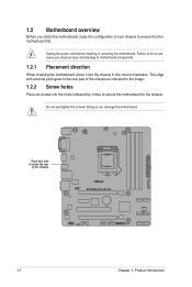
... you physical injury and damage to motherboard components. 1.2.1 Placement direction When installing the motherboard, place it into the holes indicated by circles to secure the motherboard to the rear part of the chassis as indicated in the image. 1.2.2 Screw holes Place six ...your chassis to ensure that the motherboard fits. Unplug the power cord before installing or removing the motherboard. The edge with external ports goes to the chassis. Doing so can cause you install the motherboard, study the configuration of the chassis B150M-PLUS D3 1-2 Chapter 1: Product introduction Do...
... you physical injury and damage to motherboard components. 1.2.1 Placement direction When installing the motherboard, place it into the holes indicated by circles to secure the motherboard to the rear part of the chassis as indicated in the image. 1.2.2 Screw holes Place six ...your chassis to ensure that the motherboard fits. Unplug the power cord before installing or removing the motherboard. The edge with external ports goes to the chassis. Doing so can cause you install the motherboard, study the configuration of the chassis B150M-PLUS D3 1-2 Chapter 1: Product introduction Do...
User Guide
Page 14
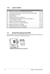
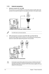
... Unit (CPU) This motherboard comes with a surface mount LGA1151 socket designed for 6th Generation Intel® Core™ i7 / i5 / i3, Pentium®, and Celeron® processors. CPU and chassis fan connectors (4-pin CPU_FAN, 4-pin CHA_FAN1/2) 3. 1.2.4 Layout contents Connectors/Jumpers/Slots/LED 1. USB 3.0 connector (20-1 pin USB3_12) 6. B150M-PLUS D3 B150M-PLUS D3 CPU socket LGA1151 1-4 Chapter...
... Unit (CPU) This motherboard comes with a surface mount LGA1151 socket designed for 6th Generation Intel® Core™ i7 / i5 / i3, Pentium®, and Celeron® processors. CPU and chassis fan connectors (4-pin CPU_FAN, 4-pin CHA_FAN1/2) 3. 1.2.4 Layout contents Connectors/Jumpers/Slots/LED 1. USB 3.0 connector (20-1 pin USB3_12) 6. B150M-PLUS D3 B150M-PLUS D3 CPU socket LGA1151 1-4 Chapter...
User Guide
Page 15
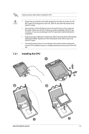
...the LGA1151 socket. • Upon purchase of the PnP cap. 1.3.1 Installing the CPU 1 A B 2 3 ASUS B150M-PLUS D3 1-5 ASUS will process Return Merchandise Authorization (RMA) requests only if the motherboard comes with the cap on the LGA1151 socket. • The product warranty does not cover damage to the PnP...that you see any damage to the socket contacts resulting from incorrect CPU installation/removal, or misplacement/loss/incorrect removal of the motherboard, ensure that the PnP cap is missing, or if you install the correct CPU designed for LGA1150, LGA1155 and LGA1156 sockets ...
...the LGA1151 socket. • Upon purchase of the PnP cap. 1.3.1 Installing the CPU 1 A B 2 3 ASUS B150M-PLUS D3 1-5 ASUS will process Return Merchandise Authorization (RMA) requests only if the motherboard comes with the cap on the LGA1151 socket. • The product warranty does not cover damage to the PnP...that you see any damage to the socket contacts resulting from incorrect CPU installation/removal, or misplacement/loss/incorrect removal of the motherboard, ensure that the PnP cap is missing, or if you install the correct CPU designed for LGA1150, LGA1155 and LGA1156 sockets ...
User Guide
Page 18
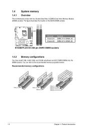
... motherboard comes with four Double Data Rate 3 (DDR3) Dual Inline Memory Module (DIMM) sockets. You can refer to the recommended memory population below. Recommended memory configurations 1-8 Chapter 1: Product introduction The figure illustrates the location of the DDR3 DIMM sockets: DIMM_A1 DIMM_A2 DIMM_B1 DIMM_B2 B150M-PLUS D3 Channel Channel A Channel B Sockets DIMM_A1 & DIMM_A2 DIMM_B1 & DIMM_B2 B150M-PLUS D3...
... motherboard comes with four Double Data Rate 3 (DDR3) Dual Inline Memory Module (DIMM) sockets. You can refer to the recommended memory population below. Recommended memory configurations 1-8 Chapter 1: Product introduction The figure illustrates the location of the DDR3 DIMM sockets: DIMM_A1 DIMM_A2 DIMM_B1 DIMM_B2 B150M-PLUS D3 Channel Channel A Channel B Sockets DIMM_A1 & DIMM_A2 DIMM_B1 & DIMM_B2 B150M-PLUS D3...
User Guide
Page 19
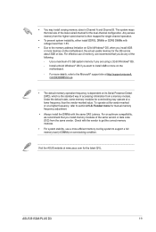
...motherboard, the actual usable memory for overclocking may install varying memory sizes in Channel A and Channel B. com/kb/929605/en-us. • The default memory operation frequency is dependent on its Serial Presence Detect (SPD), which is then mapped for the dual-channel configuration. ASUS B150M-PLUS D3... 1-9 Any excess memory from a memory module. To operate at the vendor-marked or at www.asus.com for manual memory frequency adjustment. • Always install the DIMMs ...
...motherboard, the actual usable memory for overclocking may install varying memory sizes in Channel A and Channel B. com/kb/929605/en-us. • The default memory operation frequency is dependent on its Serial Presence Detect (SPD), which is then mapped for the dual-channel configuration. ASUS B150M-PLUS D3... 1-9 Any excess memory from a memory module. To operate at the vendor-marked or at www.asus.com for manual memory frequency adjustment. • Always install the DIMMs ...
User Guide
Page 21
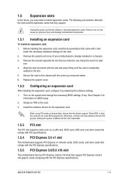
...card. 3. Assign an IRQ to install expansion cards. 1.5 Expansion slots In the future, you may cause you physical injury and damage motherboard components. 1.5.1 Installing an expansion card To install an expansion card: 1. Align the card connector with the PCI Express specifications. See ...other cards that comply with the PCI Express specifications. 1.5.5 PCI Express 3.0/2.0 x16 slot This motherboard has two PCI Express 3.0/2.0 x16 slots that came with the screw you removed earlier. 6. ASUS B150M-PLUS D3 1-11 Turn on shared slots, ensure that the drivers support "Share IRQ" or that ...
...card. 3. Assign an IRQ to install expansion cards. 1.5 Expansion slots In the future, you may cause you physical injury and damage motherboard components. 1.5.1 Installing an expansion card To install an expansion card: 1. Align the card connector with the PCI Express specifications. See ...other cards that comply with the PCI Express specifications. 1.5.5 PCI Express 3.0/2.0 x16 slot This motherboard has two PCI Express 3.0/2.0 x16 slots that came with the screw you removed earlier. 6. ASUS B150M-PLUS D3 1-11 Turn on shared slots, ensure that the drivers support "Share IRQ" or that ...

User Guide
Page 22
... provide sufficient power when running CrossFireX™ mode. XHCI Controller shared - - - - - - - 1-12 Chapter 1: Product introduction PCIEx16_2 shared - - - - - - - PCI 1 - - IRQ assignments for B150M-PLUS D3 A B C D E F G H PCIEx16_1 shared - - - - - - - Realtek 8111H LAN Controller - - - SATA Controller shared - - - - - - - PCIEx1_1 shared - - - - -... (gray) for a PCI Express x16 graphics card to the motherboard connector labeled CHA_FAN1/2 when using multiple graphics cards for better thermal environment. HD Audio shared - - - - - ...
... provide sufficient power when running CrossFireX™ mode. XHCI Controller shared - - - - - - - 1-12 Chapter 1: Product introduction PCIEx16_2 shared - - - - - - - PCI 1 - - IRQ assignments for B150M-PLUS D3 A B C D E F G H PCIEx16_1 shared - - - - - - - Realtek 8111H LAN Controller - - - SATA Controller shared - - - - - - - PCIEx1_1 shared - - - - -... (gray) for a PCI Express x16 graphics card to the motherboard connector labeled CHA_FAN1/2 when using multiple graphics cards for better thermal environment. HD Audio shared - - - - - ...
User Guide
Page 26
COM PIN 1 RXD DTR DSR CTS DCD TXD GND RTS RI B150M-PLUS D3 B150M-PLUS D3 Serial port (COM) connector The COM module is for a serial (COM) port. Insufficient air flow inside the system may damage the motherboard components. These are not jumpers! CPU and chassis fan connectors (4-pin CPU_FAN, 4-pin CHA_FAN 1/2) Connect the fan cables to...
COM PIN 1 RXD DTR DSR CTS DCD TXD GND RTS RI B150M-PLUS D3 B150M-PLUS D3 Serial port (COM) connector The COM module is for a serial (COM) port. Insufficient air flow inside the system may damage the motherboard components. These are not jumpers! CPU and chassis fan connectors (4-pin CPU_FAN, 4-pin CHA_FAN 1/2) Connect the fan cables to...
User Guide
Page 27
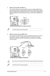
...the motherboard! 3. USB1112 USB910 USB+5V USB_P9USB_P9+ GND NC USB+5V USB_P11USB_P11+ GND NC B150M-PLUS D3 PIN 1 PIN 1 USB+5V USB_P10USB_P10+ GND USB+5V USB_P12USB_P12+ GND B150M-PLUS D3 USB2.0 connectors Never connect a 1394 cable to 480Mbps connection speed. B150M-PLUS D3 ... 1 USB3+5V IntA_P1_SSRXIntA_P1_SSRX+ GND IntA_P1_SSTXIntA_P1_SSTX+ GND IntA_P1_DIntA_P1_D+ GND B150M-PLUS D3 USB3.0 Front panel connector The USB 3.0 module is for USB 2.0 ports. The USB 2.0 module is purchased separately. ASUS B150M-PLUS D3 1-17 With an installed USB 3.0 module, you to 5...
...the motherboard! 3. USB1112 USB910 USB+5V USB_P9USB_P9+ GND NC USB+5V USB_P11USB_P11+ GND NC B150M-PLUS D3 PIN 1 PIN 1 USB+5V USB_P10USB_P10+ GND USB+5V USB_P12USB_P12+ GND B150M-PLUS D3 USB2.0 connectors Never connect a 1394 cable to 480Mbps connection speed. B150M-PLUS D3 ... 1 USB3+5V IntA_P1_SSRXIntA_P1_SSRX+ GND IntA_P1_SSTXIntA_P1_SSTX+ GND IntA_P1_DIntA_P1_D+ GND B150M-PLUS D3 USB3.0 Front panel connector The USB 3.0 module is for USB 2.0 ports. The USB 2.0 module is purchased separately. ASUS B150M-PLUS D3 1-17 With an installed USB 3.0 module, you to 5...
User Guide
Page 29
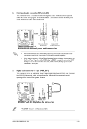
...SPDIFOUT GND B150M-PLUS D3 SPDIF_OUT B150M-PLUS D3 Digital audio connector The S/PDIF module is set to [AC97]. 6. ASUS B150M-PLUS D3 1-19 Digital audio connector (4-1 pin SPDIF_OUT) This connector is for an additional Sony/Philips Digital Interface (S/PDIF) port. Connect one end of the motherboard's high-... MIC2 MICPWR Line out_R NC Line out_L PORT1 L PORT1 R PORT2 R SENSE_SEND PORT2 L B150M-PLUS D3 HD-audio-compliant Legacy AC'97 pin definition compliant definition B150M-PLUS D3 Front panel audio connector • We recommend that supports either HD Audio or legacy AC`...
...SPDIFOUT GND B150M-PLUS D3 SPDIF_OUT B150M-PLUS D3 Digital audio connector The S/PDIF module is set to [AC97]. 6. ASUS B150M-PLUS D3 1-19 Digital audio connector (4-1 pin SPDIF_OUT) This connector is for an additional Sony/Philips Digital Interface (S/PDIF) port. Connect one end of the motherboard's high-... MIC2 MICPWR Line out_R NC Line out_L PORT1 L PORT1 R PORT2 R SENSE_SEND PORT2 L B150M-PLUS D3 HD-audio-compliant Legacy AC'97 pin definition compliant definition B150M-PLUS D3 Front panel audio connector • We recommend that supports either HD Audio or legacy AC`...
User Guide
Page 32
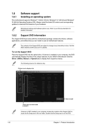
... your computer, browse the contents of the Support DVD to display their respective menus. Double-click the Setup.exe to your ASUS motherboard. The contents of your hardware. To run the DVD. 1-22 Chapter 1: Product introduction Click the Driver, Utilities, Manual,... Support DVD information The Support DVD that comes with the motherboard package contains the drivers, software applications, and utilities that you can install to change at www.asus.com for updates. 1.8 Software support 1.8.1 Installing an operating system This motherboard supports Windows® 7 (32-bit / 64-bit),...
... your computer, browse the contents of the Support DVD to display their respective menus. Double-click the Setup.exe to your ASUS motherboard. The contents of your hardware. To run the DVD. 1-22 Chapter 1: Product introduction Click the Driver, Utilities, Manual,... Support DVD information The Support DVD that comes with the motherboard package contains the drivers, software applications, and utilities that you can install to change at www.asus.com for updates. 1.8 Software support 1.8.1 Installing an operating system This motherboard supports Windows® 7 (32-bit / 64-bit),...
User Guide
Page 33
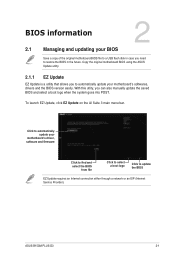
Copy the original motherboard BIOS using the ASUS Update utility. 2.1.1 EZ Update EZ Update is a utility that allows you to update the BIOS EZ Update requires an Internet connection either through a network or an ISP (Internet Service Provider). ASUS B150M-PLUS D3 2-1 With this utlity, you need... to restore the BIOS in the future. Click to automatically update your motherboard's driver, software and firmware Click to find and select the BIOS from ...
Copy the original motherboard BIOS using the ASUS Update utility. 2.1.1 EZ Update EZ Update is a utility that allows you to update the BIOS EZ Update requires an Internet connection either through a network or an ISP (Internet Service Provider). ASUS B150M-PLUS D3 2-1 With this utlity, you need... to restore the BIOS in the future. Click to automatically update your motherboard's driver, software and firmware Click to find and select the BIOS from ...

User Guide
Page 35
... BIOS file using the motherboard support DVD or a USB flash drive that contains the updated BIOS file. • Before using this section are for the BIOS file. Ensure that your USB flash drive is in single partition and in your USB flash drive. ASUS B150M-PLUS D3 2-3 Turn on your ...computer has a DVD optical drive. Before updating BIOS • Prepare the motherboard support DVD and a USB flash drive. • Download the latest BIOS file and BIOS ...
... BIOS file using the motherboard support DVD or a USB flash drive that contains the updated BIOS file. • Before using this section are for the BIOS file. Ensure that your USB flash drive is in single partition and in your USB flash drive. ASUS B150M-PLUS D3 2-3 Turn on your ...computer has a DVD optical drive. Before updating BIOS • Prepare the motherboard support DVD and a USB flash drive. • Download the latest BIOS file and BIOS ...

User Guide
Page 38
... POST: Press ++ simultaneously. Press to update the BIOS or configure its routines. Entering BIOS Setup at startup To enter BIOS Setup at www.asus.com to enter BIOS Setup using the BIOS Setup program. See section 1.6 Headers for this option only if you do not press or , ...POST continues with its parameters. Do this motherboard. • Ensure that a USB mouse is connected to the default value. If you failed to download the latest BIOS file for information on ...
... POST: Press ++ simultaneously. Press to update the BIOS or configure its routines. Entering BIOS Setup at startup To enter BIOS Setup at www.asus.com to enter BIOS Setup using the BIOS Setup program. See section 1.6 Headers for this option only if you do not press or , ...POST continues with its parameters. Do this motherboard. • Ensure that a USB mouse is connected to the default value. If you failed to download the latest BIOS file for information on ...
User Guide
Page 39
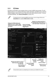
Displays the CPU/motherboard temperature, CPU voltage output, CPU/chassis fan speed, and SATA information Displays the system properties of the basic system information, and allows you enter the ... language, system performance mode, fan profile and boot device priority. Click to the system. To access the Advanced Mode, click Advanced Mode(F7) or press . ASUS B150M-PLUS D3 2-7 2.2.1 EZ Mode By default, the EZ Mode screen appears when you to the Setup Mode item in section 2.8 Boot menu for entering the BIOS setup...
Displays the CPU/motherboard temperature, CPU voltage output, CPU/chassis fan speed, and SATA information Displays the system properties of the basic system information, and allows you enter the ... language, system performance mode, fan profile and boot device priority. Click to the system. To access the Advanced Mode, click Advanced Mode(F7) or press . ASUS B150M-PLUS D3 2-7 2.2.1 EZ Mode By default, the EZ Mode screen appears when you to the Setup Mode item in section 2.8 Boot menu for entering the BIOS setup...


