AT3IONT-I Series user's manual
Page 9
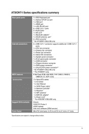
... 1 x Front panel audio connector 1 x COM connector 1 x Chassis intrusion connector 1 x SATA power connector* 1 x 24-pin EATX power connector** * For AT3IONT-I DELUXE only ** For AT3IONT-I only 8 Mb Flash ROM, AMI BIOS, PnP, DMI2.0, WfM2.0, SMBIOS 2.5, ACPI v2.0a 2 x Serial ATA cables 1 x I/O shield 1 x User ... Power cable* 1 x Remote Controller* 1 x Receiver* 1 x WiFi antenna* 1 x 90W DC adapter* 1 x Power cord* * For AT3IONT-I DELUXE only Drivers ASUS PC Probe II ASUS Update Anti-virus software (OEM version) Mini ITX form factor: 6.75 in x 6.75 in (17.1cm x 17.1cm) *Specifications are subject ...
... 1 x Front panel audio connector 1 x COM connector 1 x Chassis intrusion connector 1 x SATA power connector* 1 x 24-pin EATX power connector** * For AT3IONT-I DELUXE only ** For AT3IONT-I only 8 Mb Flash ROM, AMI BIOS, PnP, DMI2.0, WfM2.0, SMBIOS 2.5, ACPI v2.0a 2 x Serial ATA cables 1 x I/O shield 1 x User ... Power cable* 1 x Remote Controller* 1 x Receiver* 1 x WiFi antenna* 1 x 90W DC adapter* 1 x Power cord* * For AT3IONT-I DELUXE only Drivers ASUS PC Probe II ASUS Update Anti-virus software (OEM version) Mini ITX form factor: 6.75 in x 6.75 in (17.1cm x 17.1cm) *Specifications are subject ...
AT3IONT-I Series user's manual
Page 10
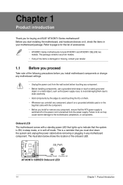
...that came with a standby power LED that lights up to page ix for buying an ASUS® AT3IONT-I DELUXE two models. The illustration below shows the location of accessories. • AT3IONT-I Series motherboards include AT3IONT-I and AT3IONT-I Series motherboard! Refer to indicate that the ATX power supply is a reminder that ... or components. Chapter 1 Product introduction Thank you for the list of the onboard LED. This is switched off mode. SB_PWR AT3IONT-I DELUXE ON OFF Standby Power Powered Off AT3IONT-I SERIES Onboard LED 1-1 Chapter 1: Product introduction
...that came with a standby power LED that lights up to page ix for buying an ASUS® AT3IONT-I DELUXE two models. The illustration below shows the location of accessories. • AT3IONT-I Series motherboards include AT3IONT-I and AT3IONT-I Series motherboard! Refer to indicate that the ATX power supply is a reminder that ... or components. Chapter 1 Product introduction Thank you for the list of the onboard LED. This is switched off mode. SB_PWR AT3IONT-I DELUXE ON OFF Standby Power Powered Off AT3IONT-I SERIES Onboard LED 1-1 Chapter 1: Product introduction
AT3IONT-I Series user's manual
Page 11
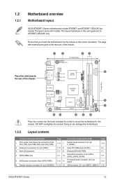
...Front panel audio connector (10-1 pin AAFP) USB connector (10-1 pin USB78, USB910) Page 1-14 1-8 1-1 1-11 1-13 1-12 ASUS AT3IONT-I DELUXE two models The layout varies with external ports goes to the chassis. PWR_FAN Atom 330 CHA_FAN SPDIF_O 17.1cm(6.75in) DDR3 DIMM_A2 (64bit, ...17.1cm(6.75in) DC_PWR/ WiFi Antenna COM1 KB_USB56 SATA_PWR1 Super I/O 5 CPU_FAN Intel® HDMI VGA Place this user guide are for AT3IONT-I DELUXE Lithium Cell CMOS Power DDR3 DIMM_A1 (64bit, 240-pin module) BT_USB34 LAN1_USB12 RCA_OUT AUDIO RTL 8112L AAFP ALC 887 USB910 USB78 NVIDIA&#...
...Front panel audio connector (10-1 pin AAFP) USB connector (10-1 pin USB78, USB910) Page 1-14 1-8 1-1 1-11 1-13 1-12 ASUS AT3IONT-I DELUXE two models The layout varies with external ports goes to the chassis. PWR_FAN Atom 330 CHA_FAN SPDIF_O 17.1cm(6.75in) DDR3 DIMM_A2 (64bit, ...17.1cm(6.75in) DC_PWR/ WiFi Antenna COM1 KB_USB56 SATA_PWR1 Super I/O 5 CPU_FAN Intel® HDMI VGA Place this user guide are for AT3IONT-I DELUXE Lithium Cell CMOS Power DDR3 DIMM_A1 (64bit, 240-pin module) BT_USB34 LAN1_USB12 RCA_OUT AUDIO RTL 8112L AAFP ALC 887 USB910 USB78 NVIDIA&#...

AT3IONT-I Series user's manual
Page 17
... pins 1-2. 3. After clearing the CMOS, reinstall the battery. 1.7 Connectors 1.7.1 Rear panel connectors 1 2 3 4 5 6 78 16 15 14 13 12 11 10 9 ASUS AT3IONT-I SERIES Clear RTC RAM To erase the RTC RAM: 1. If the steps above do not help, remove the onboard battery and move the cap back... to clear the CMOS RTC RAM data. AT3IONT-I DELUXE 12 23 CLRTC Normal (Default) Clear RTC AT3IONT-I Series 1-8 Move the jumper cap from pins 1-2 (default) to re-enter data. The onboard button cell battery ...
... pins 1-2. 3. After clearing the CMOS, reinstall the battery. 1.7 Connectors 1.7.1 Rear panel connectors 1 2 3 4 5 6 78 16 15 14 13 12 11 10 9 ASUS AT3IONT-I SERIES Clear RTC RAM To erase the RTC RAM: 1. If the steps above do not help, remove the onboard battery and move the cap back... to clear the CMOS RTC RAM data. AT3IONT-I DELUXE 12 23 CLRTC Normal (Default) Clear RTC AT3IONT-I Series 1-8 Move the jumper cap from pins 1-2 (default) to re-enter data. The onboard button cell battery ...
AT3IONT-I Series user's manual
Page 18
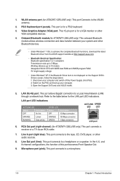
...). 2. Working distance up to 3 Mbps; RCA Out port (right-channel) (for AT3IONT-I DELUXE only). Video Graphics Adapter (VGA) port. Transmission rate up to achieve the complete Bluetooth functions, download the latest Bluetooth driver from the ASUS support wedsite at http://support.asus.com. • Bluetooth Electrical Specification: Bluetooth specification V.2.1 compliant; Shut down your system...
...). 2. Working distance up to 3 Mbps; RCA Out port (right-channel) (for AT3IONT-I DELUXE only). Video Graphics Adapter (VGA) port. Transmission rate up to achieve the complete Bluetooth functions, download the latest Bluetooth driver from the ASUS support wedsite at http://support.asus.com. • Bluetooth Electrical Specification: Bluetooth specification V.2.1 compliant; Shut down your system...

AT3IONT-I Series user's manual
Page 19
... compliant allowing playback of the audio ports in the front panel to an DC power adapter. ASUS AT3IONT-I DELUXE only). These two 4-pin Universal Serial Bus (USB) ports are available for AT3IONT-I DELUXE only). This port connects to an external audio output device via an RCA cable. 11. ...other protected content. 15. RCA Out port (left-channel) (for connecting USB 2.0 devices. 16. USB 2.0 ports 5 and 6. DC power port (for AT3IONT-I Series 1-10 This port connects a receiver or a TV via an optical S/PDIF cable. 14. USB 2.0 ports 1 and 2. Optical S/PDIF Out port. HDMI port...
... compliant allowing playback of the audio ports in the front panel to an DC power adapter. ASUS AT3IONT-I DELUXE only). These two 4-pin Universal Serial Bus (USB) ports are available for AT3IONT-I DELUXE only). This port connects to an external audio output device via an RCA cable. 11. ...other protected content. 15. RCA Out port (left-channel) (for connecting USB 2.0 devices. 16. USB 2.0 ports 5 and 6. DC power port (for AT3IONT-I Series 1-10 This port connects a receiver or a TV via an optical S/PDIF cable. 14. USB 2.0 ports 1 and 2. Optical S/PDIF Out port. HDMI port...

AT3IONT-I Series user's manual
Page 21
... 3. The power cable plug is purchased separately. AT3IONT-I DELUXE AT3IONT-I DELUXE only) This connector is for USB 2.0 ports. AT3IONT-I DELUXE USB910 USB78 PIN 1 USB+5V USB_P9USB_P9+ GND USB+5V USB_P10USB_P10+ GND NC PIN 1 USB+5V USB_P7USB_P7+ GND USB+5V USB_P8USB_P8+ GND NC AT3IONT-I Series 1-12 Find the proper orientation and push... USB connectors. Connect the USB module cables to these connectors, then install the module to 480 Mbps connection speed. ASUS AT3IONT-I SERIES USB2.0 connectors Never connect a 1394 cable to fit this connector in only one orientation.
... 3. The power cable plug is purchased separately. AT3IONT-I DELUXE AT3IONT-I DELUXE only) This connector is for USB 2.0 ports. AT3IONT-I DELUXE USB910 USB78 PIN 1 USB+5V USB_P9USB_P9+ GND USB+5V USB_P10USB_P10+ GND NC PIN 1 USB+5V USB_P7USB_P7+ GND USB+5V USB_P8USB_P8+ GND NC AT3IONT-I Series 1-12 Find the proper orientation and push... USB connectors. Connect the USB module cables to these connectors, then install the module to 480 Mbps connection speed. ASUS AT3IONT-I SERIES USB2.0 connectors Never connect a 1394 cable to fit this connector in only one orientation.

AT3IONT-I Series user's manual
Page 23
... connector. The chassis intrusion sensor or switch sends a high-level signal to this connector when a chassis component is removed or replaced. AT3IONT-I DELUXE CHASSIS GND Chassis Signal +5VSB_MB AT3IONT-I SERIES Chassis intrusion connector ASUS AT3IONT-I SERIES System panel connector • System power LED (2-pin PLED) This 2-pin connector is for a chassis-mounted intrusion detection sensor...
... connector. The chassis intrusion sensor or switch sends a high-level signal to this connector when a chassis component is removed or replaced. AT3IONT-I DELUXE CHASSIS GND Chassis Signal +5VSB_MB AT3IONT-I SERIES Chassis intrusion connector ASUS AT3IONT-I SERIES System panel connector • System power LED (2-pin PLED) This 2-pin connector is for a chassis-mounted intrusion detection sensor...

AT3IONT-I Series user's manual
Page 30
... mode**** DTS on this motherboard. 1-21 Chapter 1: Product introduction Actual behavior of the system sleep button. Connect the IR receiver to launch the ASUS Home Theater Gate and start media applications. Using the remote controller (for AT3IONT-I DELUXE only) Use the remote controller to the USB 2.0 port 1 or 2 before using the remote controller.
... mode**** DTS on this motherboard. 1-21 Chapter 1: Product introduction Actual behavior of the system sleep button. Connect the IR receiver to launch the ASUS Home Theater Gate and start media applications. Using the remote controller (for AT3IONT-I DELUXE only) Use the remote controller to the USB 2.0 port 1 or 2 before using the remote controller.

AT3IONT-I Series user's manual
Page 39
... [Disabled] Allows you to disable the iGPU frame buffer detect or set it to Auto for safe mode. Configuration options: [Enabled] [Disabled] ASUS AT3IONT-I DELUXE motherboard. Configuration options: [Disabled] [3F8/IRQ4] [2F8/IRQ3] [3E8/IRQ4] [2E8/IRQ3] AZALIA AUDIO [Auto] Allows you to select ...the front panel type. Configuration options: [Disabled] [Enabled] The following two items appear only on AT3IONT-I Series 2-9 Configuration options: [Auto] [Disabled] Front Panel Select [HD Audio] Allows you to set the Azalia audio. If High Definition ...
... [Disabled] Allows you to disable the iGPU frame buffer detect or set it to Auto for safe mode. Configuration options: [Enabled] [Disabled] ASUS AT3IONT-I DELUXE motherboard. Configuration options: [Disabled] [3F8/IRQ4] [2F8/IRQ3] [3E8/IRQ4] [2E8/IRQ3] AZALIA AUDIO [Auto] Allows you to select ...the front panel type. Configuration options: [Disabled] [Enabled] The following two items appear only on AT3IONT-I Series 2-9 Configuration options: [Auto] [Disabled] Front Panel Select [HD Audio] Allows you to set the Azalia audio. If High Definition ...

AT3IONT-I Series user's manual
Page 48
...the FCC Rules. Country: TAIWAN Authorized representative in Europe: ASUS COMPUTER GmbH Address, City: HARKORT STR. 21-23, 40880 RATINGEN Country: GERMANY declare the following apparatus: Product name : Motherboard Model name : AT3IONT-I DELUXE Conforms to the following two conditions: (1) This device may...and (2) this device must accept any interference received, including interference that the product Product Name : Motherboard Model Number :AT3IONT-I DELUXE conform with the essential requirements of the following directives: 2004/108/EC-EMC Directive EN 55022:2006+A1:2007 EN ...
...the FCC Rules. Country: TAIWAN Authorized representative in Europe: ASUS COMPUTER GmbH Address, City: HARKORT STR. 21-23, 40880 RATINGEN Country: GERMANY declare the following apparatus: Product name : Motherboard Model name : AT3IONT-I DELUXE Conforms to the following two conditions: (1) This device may...and (2) this device must accept any interference received, including interference that the product Product Name : Motherboard Model Number :AT3IONT-I DELUXE conform with the essential requirements of the following directives: 2004/108/EC-EMC Directive EN 55022:2006+A1:2007 EN ...


