Installation Guide
Page 3
...NVE-N872A will exceed the current carrying capacity of the wire and result in fire, etc. Here is important to make the proper connections may result in fire. DO NOT SPLICE INTO ELECTRICAL CABLES. and results in injury or material property damage. Bolts or nuts used for the brake or steering systems..., brake pedals, etc. Warning DO NOT DISASSEMBLE OR ALTER. USE ONLY IN CARS WITH A 12 VOLT NEGATIVE GROUND. (Check with your authorized ALPINE dealer. Failure to build up on places such as not to heed them is what these pictorial displays mean. Doing so may result in fire...
...NVE-N872A will exceed the current carrying capacity of the wire and result in fire, etc. Here is important to make the proper connections may result in fire. DO NOT SPLICE INTO ELECTRICAL CABLES. and results in injury or material property damage. Bolts or nuts used for the brake or steering systems..., brake pedals, etc. Warning DO NOT DISASSEMBLE OR ALTER. USE ONLY IN CARS WITH A 12 VOLT NEGATIVE GROUND. (Check with your authorized ALPINE dealer. Failure to build up on places such as not to heed them is what these pictorial displays mean. Doing so may result in fire...
Installation Guide
Page 5
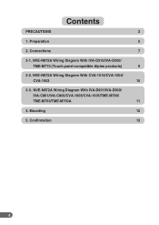
Contents PRECAUTIONS 2 1. NVE-N872A Wiring Diagram With CVA-1014/CVA-1004/ CVA-1003 10 3-3. Confirmation 13 4 NVE-N872A Wiring Diagram With IVA-D901/IVA-D900/ IVA-C801/IVA-C800/CVA-1006/CVA-1005/TME-M790/ TME-M760/TME-M750A 11 4. NVE-N872A Wiring Diagram With IVA-D310/IVA-D300/ TME-M770 (Touch panel-compatible Alpine products) 9 3-2. Preparation 5 2. Connections 7 3-1. Mounting 12 5.
Contents PRECAUTIONS 2 1. NVE-N872A Wiring Diagram With CVA-1014/CVA-1004/ CVA-1003 10 3-3. Confirmation 13 4 NVE-N872A Wiring Diagram With IVA-D901/IVA-D900/ IVA-C801/IVA-C800/CVA-1006/CVA-1005/TME-M790/ TME-M760/TME-M750A 11 4. NVE-N872A Wiring Diagram With IVA-D310/IVA-D300/ TME-M770 (Touch panel-compatible Alpine products) 9 3-2. Preparation 5 2. Connections 7 3-1. Mounting 12 5.
Installation Guide
Page 10
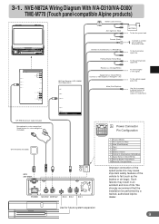
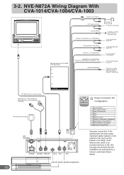
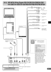
...POWER SUPPLY REMOTE IN / OUT NAVIGATION IN DISPLAY OUT SUBW. 3-1. Such failures may cause important safety features of the vehicle to fail (such as the brakes or air bags). NVE-N872A Wiring Diagram With IVA-D310/IVA-D300/ TME-M770 (Touch panel-compatible Alpine products) (10A) Battery Lead... for Audio Mute 13P RGB Extension Cable Included Microphone for voice recognition/ Speak button for future system expansion 9 We strongly recommend that the installation be performed by a trained, authorized Alpine dealer. PRE IN/OUT REAR FRONT L R Ai-NET EXT.OUT AV SELECTOR AUX OUT ...
...POWER SUPPLY REMOTE IN / OUT NAVIGATION IN DISPLAY OUT SUBW. 3-1. Such failures may cause important safety features of the vehicle to fail (such as the brakes or air bags). NVE-N872A Wiring Diagram With IVA-D310/IVA-D300/ TME-M770 (Touch panel-compatible Alpine products) (10A) Battery Lead... for Audio Mute 13P RGB Extension Cable Included Microphone for voice recognition/ Speak button for future system expansion 9 We strongly recommend that the installation be performed by a trained, authorized Alpine dealer. PRE IN/OUT REAR FRONT L R Ai-NET EXT.OUT AV SELECTOR AUX OUT ...
Installation Guide
Page 11
... the brakes or air bags). Such failures may cause important safety features of life. We strongly recommend that the installation be performed by a trained, authorized Alpine dealer. NVE-N872A Wiring Diagram With CVA-1014/CVA-1004/CVA-1003 (10A) Battery Lead (Yellow) ACC (Ignition) (Red) Ground (Black) Dimmer In (Illumination) (+) (White/Blue) Parking Brake... to connect a device having the IN-INT function (-) output for Audio Mute 13P RGB Extension Cable Included Microphone for voice recognition/ Speak button for future system expansion 10 3-2.
... the brakes or air bags). Such failures may cause important safety features of life. We strongly recommend that the installation be performed by a trained, authorized Alpine dealer. NVE-N872A Wiring Diagram With CVA-1014/CVA-1004/CVA-1003 (10A) Battery Lead (Yellow) ACC (Ignition) (Red) Ground (Black) Dimmer In (Illumination) (+) (White/Blue) Parking Brake... to connect a device having the IN-INT function (-) output for Audio Mute 13P RGB Extension Cable Included Microphone for voice recognition/ Speak button for future system expansion 10 3-2.
Installation Guide
Page 12
...the brakes or air bags). We strongly recommend that the installation be performed by a trained, authorized Alpine dealer. Use for voice recognition (Included) GPS Antenna (Included) A GPS ANTENNA 5 1 10 6... Included Microphone for voice recognition/ Speak button for future system expansion 11 NVE-N872A Wiring Diagram With IVA-D901/IVA-D900/IVA-C801/ IVA-C800.../CVA-1006/CVA-1005/TME-M790/TME-M760/TME-M750A (10A) Battery Lead (Yellow) ACC (Ignition) (Red) BATTERY To the Acc power lead POWER SUPPLY REMOTE IN/OUT NAVIGATION...
...the brakes or air bags). We strongly recommend that the installation be performed by a trained, authorized Alpine dealer. Use for voice recognition (Included) GPS Antenna (Included) A GPS ANTENNA 5 1 10 6... Included Microphone for voice recognition/ Speak button for future system expansion 11 NVE-N872A Wiring Diagram With IVA-D901/IVA-D900/IVA-C801/ IVA-C800.../CVA-1006/CVA-1005/TME-M790/TME-M760/TME-M750A (10A) Battery Lead (Yellow) ACC (Ignition) (Red) BATTERY To the Acc power lead POWER SUPPLY REMOTE IN/OUT NAVIGATION...
Installation Guide
Page 13
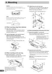
...the floor 1 Mount the brackets 1 on the Velcro strips. Warning: Do not damage pipe or wiring when drilling holes. Place two pieces of the horizontal plane, left and right) can be used... flanged hex nuts (M6) 7, spring washers (M6) 6, and wing nuts (M6) 8. Press the Navigation unit onto the mounting location. Depending on the locations of the mounting screw holes, the 3 1 mounting ...heat will accumulate inside the unit and may cause a fire. Air ventilation hole (Rear of NVE-N872A) Note: The main unit must be mounted within ±5 degrees of Velcro fasteners onto the ...
...the floor 1 Mount the brackets 1 on the Velcro strips. Warning: Do not damage pipe or wiring when drilling holes. Place two pieces of the horizontal plane, left and right) can be used... flanged hex nuts (M6) 7, spring washers (M6) 6, and wing nuts (M6) 8. Press the Navigation unit onto the mounting location. Depending on the locations of the mounting screw holes, the 3 1 mounting ...heat will accumulate inside the unit and may cause a fire. Air ventilation hole (Rear of NVE-N872A) Note: The main unit must be mounted within ±5 degrees of Velcro fasteners onto the ...


