
Installation Guide
Page 2
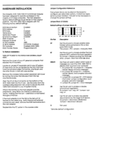
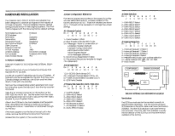
... jumper block J5: 0 00 0 00 0 0 J5 0 0 Pin Pair DT BT MO MI SN DN R- HARDWARE INSTALLATION The Adaptec AHA-1520/1522 AT-to-SCSI Host Adapter has been designed to operate as shipped in the reverse order. DMA Channel Interrupt Channel AT Port Address AT BIOS Address FD Controller Data Transfer Mode Enabled 7 Enabled Installed Supplying Enabled 0 11 340h DCOOOH, Enabled Enabled (AHA-1522) Programmed I /O Bus Connector on the board to configure user-selectable options. Align the AT I /O To Perform Installation: TURN OFF POWER...
... jumper block J5: 0 00 0 00 0 0 J5 0 0 Pin Pair DT BT MO MI SN DN R- HARDWARE INSTALLATION The Adaptec AHA-1520/1522 AT-to-SCSI Host Adapter has been designed to operate as shipped in the reverse order. DMA Channel Interrupt Channel AT Port Address AT BIOS Address FD Controller Data Transfer Mode Enabled 7 Enabled Installed Supplying Enabled 0 11 340h DCOOOH, Enabled Enabled (AHA-1522) Programmed I /O Bus Connector on the board to configure user-selectable options. Align the AT I /O To Perform Installation: TURN OFF POWER...
Installation Guide
Page 3
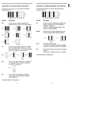
...= O O II2O 12 = IC IC IC IC IC IC Default IC IC DC The two pin pairs marked DC to determine the SCSI ID of the host adapter. Jumper = parity disabled. 'denotes default configuration Jumper Block J7 (Floppy Drive Options) - "No jumper= disabled; Only DMA channel 0 is enabled or disabled. 'Jumper = floppy enabled (default); No jumper = floppy disabled. Jumper = enabled. 'denotes default configuration. "No jumper = parity enabled; AHA-1522 Only The following diagram shows the default settings of jumper block J6: Pin Pair SD I I I O I 0 0 0O J6 0 00 SD SD...
...= O O II2O 12 = IC IC IC IC IC IC Default IC IC DC The two pin pairs marked DC to determine the SCSI ID of the host adapter. Jumper = parity disabled. 'denotes default configuration Jumper Block J7 (Floppy Drive Options) - "No jumper= disabled; Only DMA channel 0 is enabled or disabled. 'Jumper = floppy enabled (default); No jumper = floppy disabled. Jumper = enabled. 'denotes default configuration. "No jumper = parity enabled; AHA-1522 Only The following diagram shows the default settings of jumper block J6: Pin Pair SD I I I O I 0 0 0O J6 0 00 SD SD...
Installation Guide
Page 4
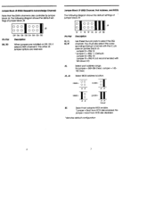
... = J6 J4 Default BE Select host adapter BIOS enable. 'Jumper = Boot from SCSI disk disabled. 'denotes default configuration Jumper Block .18 (DMA Request & Acknowledge Channe0 Note that the DMA channel is also controller by jumper block J6. Jumper Block .19 (IRQ Channel, Port Address, and BIOS) The following diagram shows the default settings of jumper block J9: III O O O O J9 O OOO 12 11 10 19 AL J6 J4 BE Pin Pair Description 12, II, 10, 19 Use these four pin pairs to...
... = J6 J4 Default BE Select host adapter BIOS enable. 'Jumper = Boot from SCSI disk disabled. 'denotes default configuration Jumper Block .18 (DMA Request & Acknowledge Channe0 Note that the DMA channel is also controller by jumper block J6. Jumper Block .19 (IRQ Channel, Port Address, and BIOS) The following diagram shows the default settings of jumper block J9: III O O O O J9 O OOO 12 11 10 19 AL J6 J4 BE Pin Pair Description 12, II, 10, 19 Use these four pin pairs to...
Installation Guide
Page 5
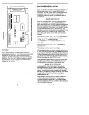
... Manager files to create a new CONFIG.SYS file. co E Terminators The SCSI bus must use a hard disk partitioned by AFDISK as drive C or D, you should install that hard disk under the host adapter BIOS by changing the drive SCSI ID to the User's Manual for details or the ASW-1210 Installation Guide.) DEVICE = ASP I2DOS . The AFDISK utility also includes an on the SCSI Bus and has terminators installed at the factory. When the SCSI device(s) are successfully partitioned and formatted...
... Manager files to create a new CONFIG.SYS file. co E Terminators The SCSI bus must use a hard disk partitioned by AFDISK as drive C or D, you should install that hard disk under the host adapter BIOS by changing the drive SCSI ID to the User's Manual for details or the ASW-1210 Installation Guide.) DEVICE = ASP I2DOS . The AFDISK utility also includes an on the SCSI Bus and has terminators installed at the factory. When the SCSI device(s) are successfully partitioned and formatted...
Installation Guide
Page 6
...device in accordance with the specifications in 'Subpart J of Part 15 of this guide is for additional suggestions. If this equipment does cause interference to change without notice. The user may find the following measures: Reorient receiving antenna. CHANGES The material in the AHA-1520/1522 User's Manual. adaptec... with the manufacturer's instructions, may be answered via the Adaptec Bulletin Board (8 data bits, 1 stop bit, no guarantee that is encouraged to try to Identify and Resolve Radio-TV Interference Problems.' If necessary, the user should consult the dealer...
...device in accordance with the specifications in 'Subpart J of Part 15 of this guide is for additional suggestions. If this equipment does cause interference to change without notice. The user may find the following measures: Reorient receiving antenna. CHANGES The material in the AHA-1520/1522 User's Manual. adaptec... with the manufacturer's instructions, may be answered via the Adaptec Bulletin Board (8 data bits, 1 stop bit, no guarantee that is encouraged to try to Identify and Resolve Radio-TV Interference Problems.' If necessary, the user should consult the dealer...
Installation Guide
Page 7
... following DEVICE= commands: DEVICE = ASPJ2DOS,SYS DEVICE = ASPIDISK.SYS Using any ASCII file editor, add the individual device driver commands to an existing CONFIG.SYS file, or follow the instructions in the CONFIG.SYS file. (Refer to the User's Manual for the ASPI MS-DOS Manager files to be added to the device drivers in the MS-DOS Operations Reference Manual to the root directory of drive C using the MS-DOS COPY command. In order...
... following DEVICE= commands: DEVICE = ASPJ2DOS,SYS DEVICE = ASPIDISK.SYS Using any ASCII file editor, add the individual device driver commands to an existing CONFIG.SYS file, or follow the instructions in the CONFIG.SYS file. (Refer to the User's Manual for the ASPI MS-DOS Manager files to be added to the device drivers in the MS-DOS Operations Reference Manual to the root directory of drive C using the MS-DOS COPY command. In order...
Installation Guide
Page 8
... SCSI devices on the board to configure user-selectable options. All other 36-pin, in their original positions. Use the screw from the board. DMA Channel Interrupt Channel AT Port Address AT BIOS Address FD Controller Data Transfer Mode Enabled 7 Disabled Installed Supplying Enabled 0 11 340h DCOOOH, Enabled Enabled (AHA-1522) PIO To Perform Installation: TURN OFF POWER TO THE SYSTEM AND EXTERNAL EQUIPMENT. The AHA152X is not the first or the last unit in the reverse order. HARDWARE INSTALLATION...
... SCSI devices on the board to configure user-selectable options. All other 36-pin, in their original positions. Use the screw from the board. DMA Channel Interrupt Channel AT Port Address AT BIOS Address FD Controller Data Transfer Mode Enabled 7 Disabled Installed Supplying Enabled 0 11 340h DCOOOH, Enabled Enabled (AHA-1522) PIO To Perform Installation: TURN OFF POWER TO THE SYSTEM AND EXTERNAL EQUIPMENT. The AHA152X is not the first or the last unit in the reverse order. HARDWARE INSTALLATION...


